Transcription
Multi-Service Business GatewaysEnterprise Session Border ControllersVoIP Media GatewaysConfiguration GuideIP-to-IP ApplicationVersion 6.8November 2013Document # LTRT-40004
Configuration GuideContentsTable of Contents1Introduction . 72Theory of Operation . 92.12.22.32.43Proxy Sets .9IP Groups .10Inbound and Outbound IP Routing Rules . 11Accounts .12IP-to-IP Routing Configuration Example . 133.13.23.33.43.53.63.73.83.93.10Step 1: Enable the IP-to-IP Capabilities . 15Step 2: Configure the Number of Media Channels . 15Step 3: Define a Trunk Group for the Local PSTN . 16Step 4: Configure the Proxy Sets. 17Step 5: Configure the IP Groups . 19Step 6: Configure the Account Table . 20Step 7: Configure IP Profiles for Voice Coders . 21Step 8: Configure Inbound IP Routing . 23Step 9: Configure Outbound IP Routing. 25Step 10: Configure Destination Phone Number Manipulation . 27Version 6.83Document #: LTRT-40004
IP-to-IP ApplicationList of FiguresFigure 2-1: Basic Schema of the Device's IP-to-IP Call Handling .9Figure 2-2: IP-to-IP Routing/Registration/Authentication of Remote IP-PBX Users (Example).10Figure 2-3: IP-to-IP Routing for IP-PBX Remote Users in Survivability Mode (Example) .11Figure 2-4: Registration with Multiple ITSP's on Behalf of IP-PBX .12Figure 3-1: SIP Trunking Setup Scenario Example .14Figure 3-2: Defining Required Media Channels .15Figure 3-3: Proxy Set ID #1 for ITSP-A .17Figure 3-4: Proxy Set ID #2 for ITSP-B .18Figure 3-5: Proxy Set ID #3 for the IP-PBX .18Figure 3-6: Defining Accounts for Registration.20Figure 3-7: Defining Coder Group ID 1 .21Figure 3-8: Defining Coder Group ID 2 .21Figure 3-9: Defining IP Profile ID 1 .22Figure 3-10: Defining Inbound IP Routing Rules .23Configuration Guide4IP-to-IP Application
Configuration GuideNoticesNoticeThis document describes AudioCodes IP-to-IP application.Information contained in this document is believed to be accurate and reliable at the time ofprinting. However, due to ongoing product improvements and revisions, AudioCodes cannotguarantee the accuracy of printed material after the Date Published nor can it acceptresponsibility for errors or omissions. Updates to this document and other documents as sathttp://www.audiocodes.com/downloads. Copyright 2013 AudioCodes Ltd. All rights reserved.This document is subject to change without notice.Date Published: November-14-2013TrademarksAudioCodes, AC, AudioCoded, Ardito, CTI2, CTI², CTI Squared, HD VoIP, HD VoIPSounds Better, InTouch, IPmedia, Mediant, MediaPack, NetCoder, Netrake, Nuera, OpenSolutions Network, OSN, Stretto, TrunkPack, VMAS, VoicePacketizer, VoIPerfect,VoIPerfectHD, What's Inside Matters, Your Gateway To VoIP and 3GX are trademarks orregistered trademarks of AudioCodes Limited. All other products or trademarks areproperty of their respective owners. Product specifications are subject to change withoutnotice.WEEE EU DirectivePursuant to the WEEE EU Directive, electronic and electrical waste must not be disposedof with unsorted waste. Please contact your local recycling authority for disposal of thisproduct.Customer SupportCustomer technical support and service are generally provided by AudioCodes'Distributors, Partners, and Resellers from whom the product was purchased. For technicalsupport for products purchased directly from AudioCodes, or for customers subscribed toAudioCodes Customer Technical Support (ACTS), contact support@audiocodes.com.Abbreviations and TerminologyEach abbreviation, unless widely used, is spelled out in full when first used.Version 6.85Document #: LTRT-40004
IP-to-IP ApplicationDocumentation FeedbackAudioCodes continually strives to produce high quality documentation. If you have any comments(suggestions or errors) regarding this document, please fill out the Documentation Feedback form onour Web site at http://www.audiocodes.com/downloads.Configuration Guide6IP-to-IP Application
Configuration Guide11. IntroductionIntroductionThe IP-to-IP application refers to call routing of calls received from the IP and forwarded toan IP destination.The device's IP-to-IP application supports IP-to-IP VoIP call routing (or SIP Trunking). TheIP-to-IP call routing application enables enterprises to seamlessly connect their IP-basedPBX (IP-PBX) to SIP trunks, typically provided by Internet Telephony Service Providers(ITSP). The device enables the enterprise to communicate with the PSTN network (localand overseas) through the ITSP, which interfaces directly with the PSTN. Therefore, theIP-to-IP application enables enterprises to replace the bundles of physical PSTN wires withSIP trunks provided by ITSPs and use VoIP to communicate within and outside theenterprise network using its standard Internet connection. At the same time, the device canalso provide an interface with the traditional PSTN network, enabling PSTN fallback in caseof IP connection failure with the ITSPs.The device also supports multiple SIP Trunking. This can be useful in scenarios where if aconnection to one ITSP fails, the call can immediately be transferred to another ITSP. Inaddition, by allowing multiple SIP trunks where each trunk is designated a specific ITSP,the device can route calls to an ITSP based on call destination (e.g., country code).In addition to providing VoIP communication within the enterprise's LAN, the deviceenables the enterprise to communicate outside of the corporate LAN using SIP Trunking.This includes remote (roaming) IP-PBX users, for example, employees using their laptopsto communicate with one another from anywhere in the world such as at airports.The IP-to-IP application can be implemented by enterprises in the following examplescenarios: VoIP between an enterprise's headquarters and remote branch offices VoIP between an enterprise and the PSTN through an ITSPThe IP-to-IP call routing capability is feature-rich, allowing interoperability with differentITSPs: Easy and smooth integration with multiple ITSP SIP trunks. Supports SIP registration and authentication with ITSP servers (on behalf of theenterprise's IP telephony system) even if the enterprise's IP telephony system does nosupport registration and authentication. Supports SIP-over-UDP, SIP-over-TCP, and SIP-over-TLS transport protocols, one ofwhich is generally required by the ITSP. Provides alternative routing to different destinations (to another ITSP or the PSTN)when the connection with an ITSP network is down. Provides fallback to the legacy PSTN telephone network upon Internet connectionfailure. Provides Transcoding from G.711 to G.729 coder with the ITSP for bandwidthreduction. Supports SRTP, providing voice traffic security toward the ITSP. IP-to-IP routing can be used in combination with the regular Gateway application. Forexample, an incoming IP call can be sent to an E1/T1 span or it can be forwarded toan IP destination.Therefore, the device provides the ideal interface between the enterprise IP-PBX and theITSP SIP trunk.The device's IP-to-IP application handles and terminates SIP methods and responses ateach leg independently: Initiating-dialog INVITE: terminated at one leg and initiated on the other leg,180\182\183\200\4xx uses the same logic and same limitations, in some cases theresult may be a different response code. OPTIONS: terminated at each leg independently.Version 6.87Document #: LTRT-40004
IP-to-IP Application INFO: only specific INFO’s (such as DTMF) are handled; other types are omitted. UPDATE: terminated at each leg independently and may cause only changes in theRTP flow - Hold\Retrieve are the only exceptions that traverse the two legs. Re-INVITE: terminated at each leg independently and may cause only changes in theRTP flow - Hold\Retrieve are the only exceptions that traverse the two legs. PRACK: terminated at each leg independently. REFER (within a dialog): terminated at each leg independently. 3xx Responses: terminated at each leg independently. 401\407 responses to initial INVITE: in case the back-to-back session is associatedwith an Account, the responses are terminated at the receiving leg; in other cases, theresponses are passed transparently. REGISTER: handled only in cases associated with a User-type IP Group - Contact,To, From specific parameters are omitted.Configuration Guide8IP-to-IP Application
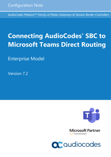
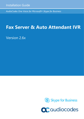
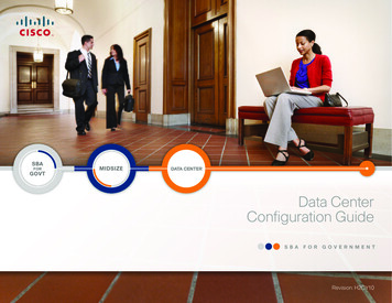
Configuration Guide22. Theory of OperationTheory of OperationThe device's IP-to-IP SIP session is performed by implementing Back-to-Back User Agent(B2BUA). The device acts as a user agent for both ends (legs) of the SIP call (from callestablishment to termination). The session negotiation is performed independently for eachcall leg, using global parameters such as coders or using IP Profiles associated with eachcall leg to assign different configuration behaviors for these two IP-to-IP call legs.If transcoding is required, the RTP streams for IP-to-IP calls traverse the device and twoDSP channels are allocated per IP-to-IP session. Therefore, the maximum number of IP-toIP sessions is 60 (corresponding to a maximum of 120 media channels that can bedesignated for IP-to-IP call routing is).If transcoding is not needed, the device supports up to 150 IP-to-IP SIP sessions (withoutusing DSP channels).The device also supports NAT traversal for SIP clients behind NAT, where the device isdefined with a global IP address.The figure below provides a simplified illustration of the device's handling of IP-to-IP callrouting:Figure 2-1: Basic Schema of the Device's IP-to-IP Call HandlingThe basic IP-to-IP call handling process can be summarized as follows:1.Incoming IP calls are identified as belonging to a specific logical entity in the networkreferred to as a Source IP Group, according to Inbound IP Routing rules.2.The Source IP Group is sent to a specific IP Group referred to as a Destination IPGroup; the IP destination address being as configured by the Proxy Set associatedwith the Destination IP Group.3.Number manipulation can be done on inbound and outbound legs.The following subsections discuss the main terms associated with the IP-to-IP call routingapplication.2.1Proxy SetsA Proxy Set is a group of Proxy servers (for Proxy load balancing and redundancy) definedby IP address or fully qualified domain name (FQDN). The Proxy Set is assigned to Servertype IP Groups only, representing the address of the IP Group to where the device sendsthe INVITE message (i.e., the destination of the call). Typically, for IP-to-IP call routing,two Proxy Sets are defined for call destination – one for each leg (i.e., one for each IPGroup) of the call (i.e., both directions).Version 6.89Document #: LTRT-40004
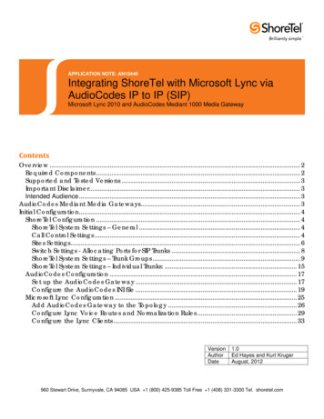
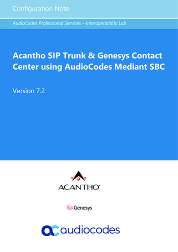
IP-to-IP Application2.2IP GroupsAn IP Group represents a logical SIP entity in the device's network environment such as anITSP SIP trunk, Proxy/Registrar server, IP-PBX, or remote IP-PBX users. The address ofthe IP Group is typically defined by its associated Proxy Set.The opposite legs of the call are each presented by an IP Group; one being a Serving IPGroup the other a Served IP Group. The Serving IP Group denotes the IP Group thatprovides service (e.g., ITSP) to the Served IP Group (e.g., IP-PBX). This is the IP Group towhere the device sends INVITE messages received from the Served IP Group as well asREGISTER messages for registering on behalf of the Served IP Group.IP Group can be a Server or User type. For Server-type IP Groups (e.g., ITSP or IP-PBX),the destination address (defined by the Proxy Set) is known. In contrast, User-type IPGroups represents groups of users whose location is dynamically obtained by the devicewhen REGISTER requests and responses traverse (or are terminated) by the device.Generally, these are remote IP-PBX users (e.g., IP phones and soft phones).For registrations of User-type IP Groups, the device updates its internal database with theAOR and Contacts of the users (see the figure below) Digest authentication using SIP401/407 responses, if needed, is done by the Serving IP Group (e.g., IP-PBX). The deviceforwards these responses directly to the remote SIP users. For a call to a registeredremote user, the device searches its dynamic database using the Request URI for an entrythat matches a registered AOR or Contact. Once an entry is found, the IP destination isobtained and a SIP request is then sent to the user.Figure 2-2: IP-to-IP Routing/Registration/Authentication of Remote IP-PBX Users (Example)Configuration Guide10IP-to-IP Application
Configuration Guide2. Theory of OperationThe device also supports the IP-to-IP call routing Survivability mode feature (see the figurebelow) for User-type IP Groups. The device stores in its database REGISTER messagessent by the clients of the User-type IP Group. If communication with the Serving IP Group(e.g., IP-PBX) fails, the User-type IP Group enters into Survivability mode in which thedevice uses its database for routing calls between the clients of the User-type IP Group.The RTP packets between the clients traverse through the device. When the Serving IPGroup is available again, the device returns to normal mode, sending INVITE andREGISTER messages to the Serving IP Group.Figure 2-3: IP-to-IP Routing for IP-PBX Remote Users in Survivability Mode (Example)2.3Inbound and Outbound IP Routing RulesThe device's IP-to-IP call routing is performed using the following two routing rule stages:1.Inbound IP Routing Rule: Identifies the received call as an IP-to-IP call based onvarious characteristics such as the call's source IP address, and assigns it to an IPGroup.2.Outbound IP Routing Rule: Determines the destination (i.e., IP address) to wherethe incoming call associated with a specific source IP Group is finally routed. Thedestination address is typically denoted by another IP Group (destination IP Group)and therefore, the call is sent to the IP address that is defined by the Proxy Setassociated with this IP Group. If the destination is a User-type IP Group, the devicesearches for a match between the request-URI of the received INVITE to an AORregistration record in the device's database. If a match is found, the INVITE is sent tothe IP address of the registered contact.Version 6.811Document #: LTRT-40004
IP-to-IP Application2.4AccountsAccounts are used by the device to register to a Serving IP Group (e.g., an ITSP) on behalfof a Served IP Group (e.g., IP-PBX). This is necessary for ITSPs that require registration toprovide services. Accounts are also used for defining user name and password for digestauthentication (with or without registration) if required by the ITSP. Multiple Accounts perServed IP Group can be configured for registration to more than one Serving IP Group(e.g., an IP-PBX that requires registering to multiple ITSP's).Figure 2-4: Registration with Multiple ITSP's on Behalf of IP-PBXConfiguration Guide12IP-to-IP Application
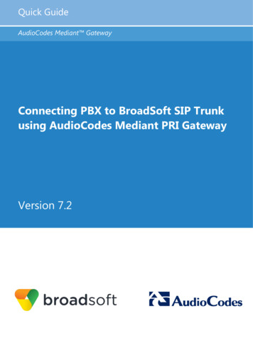
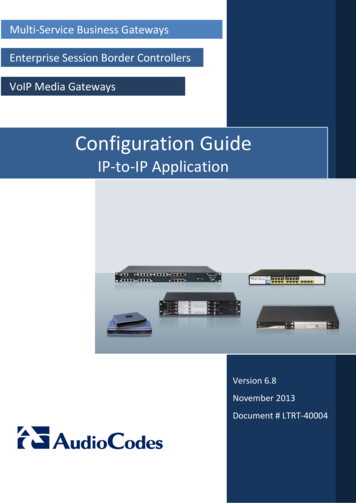
Configuration Guide33. IP-to-IP Routing Configuration ExampleIP-to-IP Routing Configuration ExampleThis section provides a typical example on how to configure IP-to-IP call routing. In thisexample, the device serves as the communication interface between the enterprise's IPPBX (located on the LAN) and the following network entities: ITSP SIP trunks (located on the WAN) Remote IP-PBX users (located on the WAN) Local PSTN networkCalls from the Enterprise are routed according to destination.This example assumes the following: The device has the public IP address 212.25.125.136 and is connected to theenterprise's firewall/NAT demilitarized zone (DMZ) network, providing the interfacebetween the IP-PBX, and two ITSP's and the local PSTN. The enterprise has an IP-PBX located behind a Firewall/NAT: IP-PBX IP address: 10.15.4.211 Transport protocol: UDP Voice coder: G.711 IP-PBX users: 4-digit length extension number and served by two ITSPs. The enterprise also includes remote IP-PBX users that communicate with the IPPBX via the device. All dialed calls from the IP-PBX consisting of four digitsstarting with digit "4" are routed to the remote IP-PBX users.Using SIP trunks, the IP-PBX connects (via the device) to two different ITSP's: ITSP-A:Implements Proxy servers with fully qualified domain names (FQDN):"Proxy1.ITSP-A" and "Proxy2.ITSP-B", using TLS. Allocates a range of PSTN numbers beginning with 1919, which isassigned to a range of IP-PBX users. Voice coder: G.723. ITSP-B: Implements Proxy servers with IP addresses 216.182.224.202 and216.182.225.202, using TCP. Allocates a range of PSTN numbers beginning with 0200, which is assignedto a range of IP-PBX users. Voice coder: G.723. Registration and authentication is required by both ITSP's, which is performed by thedevice on behalf of the IP-PBX. The SIP REGISTER messages use different URI's(host name and contact user) in the From, To, and Contact headers per ITSP as wellas username and password authentication. Outgoing calls from IP-PBX users are routed according to destination: Version 6.8 If the calls are dialed with the prefix " 81", they are routed to ITSP-A (Region A). If the calls are dialed with the prefix "9", they are routed to the local PSTNnetwork. For all other destinations, the calls are routed to ITSP-B.The device is also connected to the PSTN through a traditional T1 ISDN trunk for localincoming and outgoing calls. Calls dialed from the enterprise's IP-PBX with prefix '9'are sent to the local PSTN. In addition, in case of Internet interruption and loss ofconnection with the ITSP trunks, all calls are rerouted to the PSTN.13Document #: LTRT-40004
IP-to-IP ApplicationThe figure below provides an illustration of this example scenario:Figure 3-1: SIP Trunking Setup Scenario ExampleThe steps for configuring the device according t
Nov 14, 2013 · Configuration Guide 1. Introduction Version 6.8 7 Document #: LTRT-40004 1 Introduction The IP-to-IP application refers to ca