Transcription
Hardware Installation ManualAudioCodes MediaPack 1xx Family of Analog Media GatewaysMediaPack 124 (MP-124)
Hardware Installation ManualContentsTable of Contents1Introduction. 92Unpacking the Device . 113Physical Description . 133.13.2Physical Dimensions and Operating Environment .13Front Panel .133.2.13.2.23.3Rear Panel .153.3.13.3.23.3.34MP-124 Rev. D. 15MP-124 Rev. E . 16Ethernet LED Description . 16Mounting the Device . 174.14.25Reset Pinhole Button . 13LED Description . 14Desktop Mounting .1719-inch Rack Mounting .17Cabling the Device . 195.1Power Surge Protection and Grounding Connections .195.1.15.1.25.25.3Connecting to the Ethernet Network .27Connecting to FXS Interfaces .285.3.15.3.25.3.35.3.45.4Connecting FXS Interfaces using AudioCodes FXS Patch Panel . 29Connecting FXS Interfaces Directly to MDF . 32Securing Telco Cable to Connector with Velcro Strap. 35Connecting FXS Interfaces using a Mini Patch Panel . 38Connecting to a PC for Serial Communication .405.4.15.4.25.5MP-124 Rev. D. 205.1.1.1 Power Surge Protection and Grounding Connected to MDF throughAudioCodes FXS Patch Panel . 225.1.1.2 Power Surge Protection and Grounding using Third-party Power SurgeProtector (Circa) Connected Directly to MDF . 23MP-124 Rev. E . 245.1.2.1 Power Surge Protection and Grounding Connected to MDF throughAudioCodes FXS Patch Panel . 255.1.2.2 Power Surge Protection and Grounding Connected Directly to MDF . 26MP-124 Rev. D. 40MP-124 Rev. E . 41Connecting to Power .435.5.15.5.2AC Power Supply . 44DC Power Supply (MP-124 Rev. D Only) . 45MediaPack Analog Gateways3MP-124
MP-124List of FiguresFigure 3-1: Front Panel . 13Figure 3-2: Rear Panel of AC-Powered MP-124 Rev. D Model . 15Figure 3-3: Rear Panel of DC-Powered MP-124 Rev. D Model . 15Figure 3-4: Rear Panel of MP-124 Rev. E Model . 16Figure 4-1: Desktop Mounting . 17Figure 4-2: Attached Brackets for Rack Installation . 17Figure 5-1: MP-124 Rev. D Surge Protection and Grounding using AudioCodes FXS Patch Panel . 22Figure 5-2: MP-124 Rev. D Surge Protection and Grounding using Circa Directly to MDF . 23Figure 5-3: MP-124 Rev. E Surge Protection and Grounding using AudioCodes FXS Patch Panel . 25Figure 5-4: MP-124 Rev. E Surge Protection and Grounding Connected Directly to MDF. 26Figure 5-5: RJ-45 Connector Pinouts for Ethernet Interface . 27Figure 5-6: Connecting MP-124 to the Ethernet (e.g., Rev. E model). 27Figure 5-7: 50-pin Telco Connector . 28Figure 5-8: Orderable FXS Patch Panel . 29Figure 5-9: Connecting MP-124 Rev. D to FXS Patch Panel . 30Figure 5-10: Connecting MP-124 Rev. E to FXS Patch Panel . 31Figure 5-11: Connecting Analog Equipment to FXS Patch Panel . 32Figure 5-12: Connecting MP-124 Rev. D Directly to MDF for FXS Cabling . 33Figure 5-13: Connecting MP-124 Rev. E Directly to MDF for FXS Cabling . 34Figure 5-14: 50-Pin Telco Cable Secured to Device's Connector using Orderable Velcro Strap . 35Figure 5-15: Removing Bail Locks from Telco Connector . 35Figure 5-16: Attaching Bracket over Telco Connector (e.g., Short Screws). 36Figure 5-17: Feeding Velcro Strap through Bracket Slots . 36Figure 5-18: Sliding Cable through Velcro Strap . 36Figure 5-19: Attaching Cable Connector to Device's Telco Connector . 36Figure 5-20: Pulling Velcro Strap to Reduce Slack over Cable . 37Figure 5-21: Feeding Velcro Strap through Strap Buckle . 37Figure 5-22: Attaching Velcro Strap to Itself . 37Figure 5-20: Mini Patch Panel for FXS Interfaces . 38Figure 5-20: Connecting FXS Lines using Mini Patch Panel . 39Figure 5-23: DB-9 Connector Pinouts for Serial Interface . 40Figure 5-24: Connecting MP-124 Rev. D for Serial Communication . 40Figure 5-25: RJ-45 to DB-9 Serial Cable Adapter . 41Figure 5-26: Connecting MP-124 Rev. E for Serial Communication . 42Figure 5-27: Connecting MP-124 to AC Power Supply (e.g., Rev. E model) . 44Figure 5-28: DC Terminal Block . 45Figure 5-29: Wired DC Power Terminal Block Connected to MP-124 Rev. D . 45List of TablesTable 1-1: MP-124 Models and Support . 9Table 3-1: Physical Dimensions and Operating Environment . 13Table 3-2: Front-Panel LED Description . 14Table 3-3: MP-124 Rev. D Rear-Panel Description. 15Table 3-4: MP-124 Rev. E Rear-Panel Description . 16Table 3-5: Rear-Panel Ethernet LEDs Description . 16Table 5-1: 50-pin Telco Connector Pinouts . 28Table 5-2: RJ-45 to DB-9 Serial Cable Connector Pinouts . 41Table 5-3: Power Specifications . 43Hardware Installation Manual4Document #: LTRT-59848
Hardware Installation ManualNoticesNoticeInformation contained in this document is believed to be accurate and reliable at the time ofprinting. However, due to ongoing product improvements and revisions, AudioCodes cannotguarantee accuracy of printed material after the Date Published nor can it accept responsibilityfor errors or omissions. Updates to this document can be downloaded ocuments.This document is subject to change without notice.Date Published: April-10-2018WEEE EU DirectivePursuant to the WEEE EU Directive, electronic and electrical waste must not be disposedof with unsorted waste. Please contact your local recycling authority for disposal of thisproduct.Customer SupportCustomer technical support and services are provided by AudioCodes or by an authorizedAudioCodes Service Partner. For more information on how to buy technical support forAudioCodes products and for contact information, please visit our Web site tenance-and-support.Abbreviations and TerminologyEach abbreviation, unless widely used, is spelled out in full when first used.Throughout this manual, unless otherwise specified, the term device refers to theMediaPack MP-124 gateway.MediaPack Analog Gateways5MP-124
MP-124Related DocumentationDocument NameSIP Release NotesMP-11x & MP-124 SIP User's ManualMP-124 AC SIP Fast Track GuideMP-124D DC SIP Fast Track GuideNotes and WarningsWarning: Read and adhere to all warning statements in this document beforeinstalling the device.Warning: The device is intended to be installed only in an indoor environment, wherethe ambience temperature and humidity are controlled.Warning: Routing of FXS telephony cables: MP-124 Rev. D: Routing of FXS telephony cables outdoors can be done only inconjunction with AudioCodes’ approved surge protector (Circa model 4B3S-75)and proper installation and grounding. When done correctly, the installation willmeet ITU-T K.21 (basic) standards. MP-124 Rev. E: Routing FXS telephony cables outdoors can be done only inconjunction with a three-electrode Gas Discharge Tube (GDT) rated at 350Vlocated at the entry point of the two-wire into the building, and properly grounded.When done correctly, the installation will meet ITU-T K.21 requirements.Warning: The Ethernet port interface cabling must be routed only indoors and mustnot exit the building.Caution Electrical ShockDo not open or disassemble this device. The device carries high voltage and contactwith internal components may expose you to electrical shock and bodily harm.Hardware Installation Manual6Document #: LTRT-59848
Hardware Installation ManualNoticesWarning: The device is supplied as a sealed unit and must only be serviced byqualified service personnel.Warning: Disconnect the device from the mains and Telephone Network Voltage(TNV) before servicing.Regulatory InformationThe Regulatory Information can be viewed at http://www.audiocodes.com/downloads.Document Revision RecordLTRTDescription59815Updates for Version 6.6.59840FXS warning statement added; power surge drawings updated.59841MP-124 Rev. E model added.59842Velcro hook-and-loop cable tie for Telco connector updated.59843Max. power consumptions updated.59844Channels LED numbers when SRTP enabled.59845AC power cable warning (Japanese); MP-124 Rev. E supported software.59846Surge protection note for MP-124 Rev. E.59847Logo updated; mini-patch panel.59848Circa noteMediaPack Analog Gateways7MP-124
MP-124Documentation FeedbackAudioCodes continually strives to produce high quality documentation. If you have anycomments (suggestions or errors) regarding this document, please fill out are Installation Manual8Document #: LTRT-59848
Hardware Installation Manual11. IntroductionIntroductionThis document provides a hardware description of the MediaPack MP-124 product(hereafter, referred to as device) and step-by-step procedures for cabling the device.The MP-124 series includes the following models:Table 1-1: MP-124 Models and SupportModelFXSEthernetSerialPowerMP-124 Rev. D241DB-9AC or DCMP-124 Rev. E(MP124E/FXS/AC)24RJ-45AC Only1Note: MP-124 Rev. E is supported only from SIP Software Version 6.60A.301. Although the supported software functionality and configuration of MP-124 Rev. Dand MP-124 Rev. E are identical, they use different software firmware files (.cmp): MP-124 Rev. E: MP124E SIP version .cmp MP-124 Rev. D: MP124 SIP version .cmpMediaPack Analog Gateways9MP-124
MP-124This page is intentionally left blank.Hardware Installation Manual10Document #: LTRT-59848
Hardware Installation Manual22. Unpacking the DeviceUnpacking the DeviceFollow the procedure below for unpacking the device. To unpack MP-124:1.Open the shipping carton and carefully remove the packing materials.2.Remove the MP-124 unit from the carton.3.Check that there is no equipment damage.4.Ensure that in addition to the MP-124 unit, the package contains the following items: MP-124 Rev. D: Only for AC-powered model: AC power cord Only for DC-powered model: unwired DC terminal block with two crimpingscrews Two short equal-length brackets and bracket-to-device screws for 19-inchrack installation. Regulatory Information document. MP-124 Rev. E: Two short equal-length brackets and bracket-to-device screws for 19-inchrack installation. Regulatory Information document.5.Check, retain and process any documents.6.Notify AudioCodes or your local supplier of any damage or discrepancies.MediaPack Analog Gateways11MP-124
MP-124This page is intentionally left blank.Hardware Installation Manual12Document #: LTRT-59848
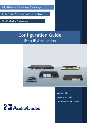
Hardware Installation Manual33. Physical DescriptionPhysical DescriptionThis chapter provides a physical description of the device.3.1Physical Dimensions and Operating EnvironmentThe device's physical dimensions and operating environment are listed in the table below:Table 3-1: Physical Dimensions and Operating EnvironmentPhysical Specification3.2DescriptionDimensions (H x W x D)44 x 445 x 269 mm (1.73 x 17.5 x 10.6 in.)Weight1.8 kg (4 lbs.)Environmental Operational: 5 to 40 C (41 to 104 F)Storage: -25 to 85 C (-13 to 185 F)Humidity: 10 to 90% non-condensingFront PanelThe device's front panel is shown in the figure below and described in the subsequentsubsections.Figure 3-1: Front Panel3.2.1Reset Pinhole ButtonThe reset pinhole button enables you to reset the device or restore the device to factorydefault settings. For more information, refer to the User's Manual.MediaPack Analog Gateways13MP-124
MP-1243.2.2LED DescriptionThe LEDs are described in the table below.Table 3-2: Front-Panel LED ngRedOnMalfunction.GreenOnValid 10/100Base-TX Ethernet BlinkingTransmitting RTP packets.RedBlinkingReceiving RTP packets.-OffNo traffic.GreenOnTelephone in off-hook position or ringing.RedOnOne of the following: Line malfunction. SRTP is enabled and device resources (DSPs)are currently unavailable for calls on theseports (their resources are "borrowed" for SRTPfunctionality). This LED state applies toChannels 19 to 24 LEDs.-OffNormal.LANControlDataChannels1-24Hardware Installation ManualFunctionDevice powered on, self-test OK.Software loading/initialization.Sending and receiving SIP messages.No traffic.14Document #: LTRT-59848
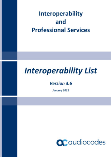
Hardware Installation Manual3.33. Physical DescriptionRear PanelThe device's rear panel provides the port interfaces.3.3.1MP-124 Rev. DThe MP-124 Rev. D rear panel is shown below (AC and DC powered models) anddescribed in the subsequent table. AC-powered model:Figure 3-2: Rear Panel of AC-Powered MP-124 Rev. D Model DC-powered model:Figure 3-3: Rear Panel of DC-Powered MP-124 Rev. D ModelTable 3-3: MP-124 Rev. D Rear-Panel DescriptionItem #LabelComponent DescriptionProtective earthing screw (mandatory for allinstallations). Accepts a 6-32 UNC screw.1100-240 V 50 - 60Hz 0.8AAC power supply socket.Note: Applicable only to the AC-powered model.48V 1.3ADC inlet for a DC terminal block.Note: Applicable only to the DC-powered model.23ANALOG FXSLINES 1–2450-pin Telco connector, providing up to 24 analog lines.4RS-232DB-9-pin male port for serial (RS-232) communication.5ETHERNETMediaPack Analog GatewaysRJ-45 port for 10/100Base-TX Ethernet interface.15MP-124
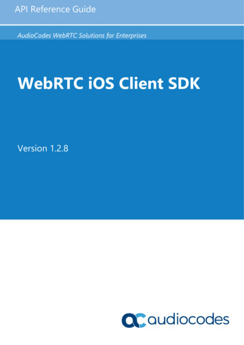
MP-1243.3.2MP-124 Rev. EThe MP-124 Rev. E rear panel is shown below and described in the subsequent table.Figure 3-4: Rear Panel of MP-124 Rev. E ModelTable 3-4: MP-124 Rev. E Rear-Panel DescriptionItem #LabelProtective earthing screw (mandatory for allinstallations). Accepts a 6-32 UNC screw.13.3.3Component Description2100-240 V 50 - 60Hz 1A3ANALOG FXSLINES 1–244RS-2325ETHERNETAC power supply socket.50-pin Telco connector, providing up to 24 FXS analoglines.RJ-45 port for serial (RS-232) communication.RJ-45 port for 10/100Base-TX Ethernet interface.Ethernet LED DescriptionThe RJ-45 Ethernet port for Ethernet interface (labeled ETHERNET), provides LEDs thatindicate Ethernet status, as described in the table below.Table 3-5: Rear-Panel Ethernet LEDs alid 10/100Base-TX Ethernet connection.RedOnMalfunction.Hardware Installation Manual16Document #: LTRT-59848
Hardware Installation Manual44. Mounting the DeviceMounting the DeviceThe device can be mounted in one of the following ways:4.1 Desktop mounting – see 'Desktop Mounting' on page 17 Installed in a standard 19-inch rack – see '19-inch Rack Mounting' on page 17Desktop MountingFor desktop mounting, no brackets are required. Simply place the device on a desktop inthe required position.Figure 4-1: Desktop Mounting4.219-inch Rack MountingThe device can be installed in
Apr 10, 2018 · Related Documentation Document Name SIP Release Notes MP-11x & MP-124 SIP User's Manual MP-124 AC SIP Fast Track Guide MP-124D DC SIP Fast Track Guide Notes and Warning