Transcription
Tape and Reel Specificationsand Packaging SpecificationsPageTape and Reel Specifications . . . . . . . . . . . . . . . . . . . 5.12–2Embossed Tape and Reel Ordering Information . 5.12–3Embossed Tape and Reel Data for Discretes . . . 5.12–4Lead Tape Packaging Standardsfor Axial–Lead Components . . . . . . . . . . . . . . . . . 5.12–6Packaging Specifications . . . . . . . . . . . . . . . . . . . . . . . 5.12–7TO–92 EIA Radial Tape in Fan Fold Boxor on Reel . . . . . . . . . . . . . . . . . . . . . . . . . . . . . . . . . 5.12–7Fan Fold Box Styles . . . . . . . . . . . . . . . . . . . . . . . . . 5.12–9Adhesion Pull Tests . . . . . . . . . . . . . . . . . . . . . . . . . 5.12–9Reel Styles . . . . . . . . . . . . . . . . . . . . . . . . . . . . . . . 5.12–10DO–35, DO–41, Surmetic 30 Radial Tape inFan Fold Box or On Reel . . . . . . . . . . . . . . . . . . . 5.12–11Motorola Master Selection Guide5.12–1Tape and Reel Specifications
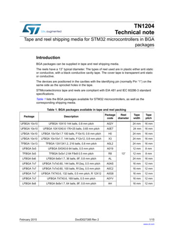
Tape and Reel Specificationsand Packaging SpecificationsEmbossed Tape and Reel is used to facilitate automatic pick and place equipment feed requirements. The tape is used as theshipping container for various products and requires a minimum of handling. The antistatic/conductive tape provides a securecavity for the product when sealed with the “peel–back” cover tape. SO–8, Micro8, OPTO SO–8, SOT–223, SMA, SMB in12 mm Tape DPAK, PFP–16, SO–14, SO–16, SMC, TSSOP–16,TSSOP–20, 430 and 430B in 16 mm Tape D2PAK, D3PAK, 6–Pin Optoisolators in 24 mm TapeTwo Reel Sizes Available (7″ and 13″)Used for Automatic Pick and Place Feed SystemsMinimizes Product HandlingEIA 481, –1, –2SOD–123, SC–59, SC–70/SOT–323, SC–70ML/SOT–363,SOT–23, SOT–143, TSOP–6, in 8 mm TapeUse the standard device title and add the required suffix as listed in the option table on the following page. Note that the individualreels have a finite number of devices depending on the type of product contained in the tape. Also note the minimum lot size isone full reel for each line item, and orders are required to be in increments of the single reel quantity.SOD–123SC–59, TSOP–6,SC–70/SOT–323, SOT–238 mm8 mmSC–70ML/SOT–363T1 ORIENTATION8 mmSC–70ML/SOT–363T2 ORIENTATIONSOT–1438 mm8 mmMicro8, SO–8,OPTO SO–8SOT–22312 mmSO–14, 1612 mm16 mmPFP–16SMA/SMBSMC12 mm16 mm16 mm430, 430B16 mmTSSOP–16TSSOP–2016 mm16 mmDIRECTIONOF FEEDDPAK16 mmTape and Reel SpecificationsD2PAKD3PAK6–Pin Optoisolators24 mm24 mm24 mm5.12–2Motorola Master Selection Guide
EMBOSSED TAPE AND REEL ORDERING INFORMATIONPackageTape Width(mm)Pitchmm(inch)Reel Sizemm(inch)Devices Per Reeland MinimumOrder QuantityDeviceSuffixDPAK168.0 0.1 (.315 .004)330(13)2,500T4D2PAK2416.0 0.1 (.630 .004)330(13)800T4D3PAK2424.0 0.1 (.945 .004)330(13)500RLSC–59/TSOP–684.0 0.1 (.157 .004)178(7)3,000T1SC–70/SOT–323884.0 0.1 (.157 63884.0 0.1 (.157 .004)178178(7)(7)3,0003,000T1T2SMA128.0 0.1 (.315 .004)330(13)5,000T3SMB128.0 0.1 (.315 .004)330(13)2,500T3SMC168.0 0.1 (.315 .004)330(13)2,500T3SO–8, OPTO SO–812128.0 0.1 (.315 .004)178330(7)(13)5002,500R1R2SO–1416168.0 0.1 (.315 .004)178330(7)(13)5002,500R1R2SO–1616168.0 0.1 (.315 .004)178330(7)(13)5002,500R1R2SOD–123884.0 0.1 (.157 .004)178330(7)(13)3,00010,000T1T3SOT–23884.0 0.1 (.157 .004)178330(7)(13)3,00010,000T1T3SOT–143884.0 0.1 (.157 .004)178330(7)(13)3,00010,000T1T3SOT–22312128.0 0.1 (.315 .004)178330(7)(13)1,0004,000T1T36–Pin Optoisolators2412.0 0.1 (.472 .004)330(13)1000R2Micro8128.0 0.1 (.315 .003)330(13)4000R2PFP–161612.0 0.1 (.471 .004)330(13)1,500R2TSSOP–16168.0 0.1 (.315 .004)330(13)2,500R2TSSOP–20168.0 0.1 (.315 .004)330(13)2,500R2430, 430B168.0 0.1 (.315 .004)178(7)500R1Motorola Master Selection Guide5.12–3Tape and Reel Specifications
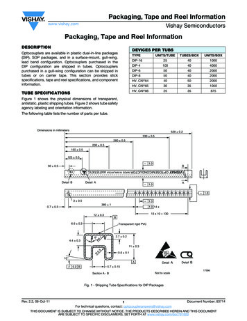
EMBOSSED TAPE AND REEL DATA FOR DISCRETESCARRIER TAPE SPECIFICATIONSP0KP2Dt10 Pitches Cumulative Tolerance on Tape 0.2 mm( 0.008″)ETop CoverTapeA0K0B1FWB0SeeNote 1PFor Machine Reference OnlyIncluding Draft and RADIIConcentric Around B0D1For Components2.0 mm x 1.2 mm and LargerCenter Linesof CavityEmbossmentUser Direction of Feed* Top Cover TapeThickness (t1)0.10 mm(.004″) Max.Bar Code LabelR MinTape and ComponentsShall Pass Around Radius “R”Without DamageBending Radius10 Embossed Carrier100 mm(3.937″)Maximum Component RotationEmbossment1 mm MaxTypical ComponentCavity Center LineTape1 mm(.039″) MaxTypical ComponentCenter Line250 mm(9.843″)Camber (Top View)Allowable Camber To Be 1 mm/100 mm Nonaccumulative Over 250 mmDIMENSIONSTapeSizeB1 MaxDD1EFKP0P2R MinT MaxW Max8 mm4.55 mm(.179″)1.0 Min(.039″)1.75 0.1 mm((.069 .004″))3.5 0.05 mm(.138 .002″)2.4 mm Max(.094″)4.0 0.1 mm(.157( .004″))2.0 0.1 mm(.079( .002″))25 mm(.98″)0.6 mm((.024″))8.3 mm(.327″)12 mm8.2 mm(.323″)1.5 0.1 mm– 0.0( 059 .004″(.059004″– 0.0)5.5 0.05 mm(.217 .002″)6.4 mm Max(.252″)16 mm12.1 mm(.476″)7.5 0.10 mm(.295 .004″)7.9 mm Max(.311″)16.3 mm(.642″)24 mm20.1 mm(.791″)11.5 0.1 mm(.453 .004″)11.9 mm Max(.468″)24.3 mm(.957″)1.5 mm Min(.060″)()30 mm(1.18″)()12 .30 mm(.470 .012″)Metric dimensions govern — English are in parentheses for reference only.NOTE 1: A0, B0, and K0 are determined by component size. The clearance between the components and the cavity must be within .05 mm min. to .50 mm max.,NOTE 1: the component cannot rotate more than 10 within the determined cavity.NOTE 2: If B1 exceeds 4.2 mm (.165) for 8 mm embossed tape, the tape may not feed through all tape feeders.NOTE 3: Pitch information is contained in the Embossed Tape and Reel Ordering Information on pg. 5.12–3.Tape and Reel Specifications5.12–4Motorola Master Selection Guide
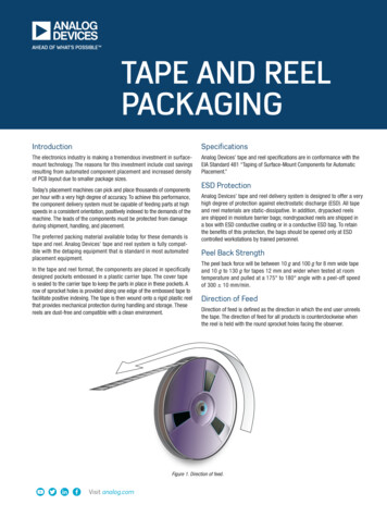
EMBOSSED TAPE AND REEL DATA FOR DISCRETEST MaxOutside DimensionMeasured at Edge1.5 mm Min(.06″)A13.0 mm 0.5 mm(.512″ .002″)20.2 mm Min(.795″)50 mm Min(1.969″)Full RadiusGSizeA MaxG8 mm330 mm(12.992″)8.4 mm 1.5 mm, – 0.0(.33″ .059″, – 0.00)14.4 mm(.56″)12 mm330 mm(12.992″)12.4 mm 2.0 mm, – 0.0(.49″ .079″, – 0.00)18.4 mm(.72″)16 mm360 mm(14.173″)16.4 mm 2.0 mm, – 0.0(.646″ .078″, – 0.00)22.4 mm(.882″)24 mm360 mm(14.173″)24.4 mm 2.0 mm, – 0.0(.961″ .070″, – 0.00)30.4 mm(1.197″)Inside DimensionMeasured Near HubT MaxReel DimensionsMetric Dimensions Govern — English are in parentheses for reference onlyMotorola Master Selection Guide5.12–5Tape and Reel Specifications
LEAD TAPE PACKAGING STANDARDS FOR AXIAL–LEAD COMPONENTSProductCategoryCase TypeDeviceTitleSuffixMPQQuantityPer Reel(Item 3.3.7)ComponentSpacingA DimensionTapeSpacingB DimensionReelDimensionCReelDimensionD (Max)Max OffAlignmentECase 17–02Surmetic 40 &600 Watt TVSRL40000.2 /– 0.0152.062 /– 0.0593140.047Case 41A–021500 Watt TVSRL415000.4 /– 0.022.062 /– 0.0593140.047Case 51–02DO–7 Glass(For Reference only)RL30000.2 /– 0.022.062 /– 0.0593140.047Case 59–03DO–41 Glass &DO–41 Surmetic 30RL60000.2 /– 0.0152.062 /– 0.0593140.047Case 59–04500 Watt TVSRL50000.2 /– 0.022.062 /– 0.0593140.047RL8000.4 /– 0.021.875 /– 0.0593140.047RectifierRectifierCase 194–04110 Amp TVS(Automotive)RectifierCase 267–02RectifierRL15000.4 /– 0.022.062 /– 0.0593140.047Case 299–02DO–35 GlassRL50000.2 /– 0.022.062 /– 0.0593140.047Table 1. Packaging Details (all dimensions in inches)Overall LGItem 3.1.2Kraft PaperReelBRoll PadAItem 3.1.1Max OffAlignmentEContainerTape, BlueItem 3.2(Cathode)Item 3.3.5Both SidesTape, WhiteItem 3.2(Anode)Figure 1. Reel PackingD1D20.250Item 3.3.20.031Item 3.3.5Figure 2. Component SpacingOptional Design1.1883.5 Dia.Item 3.4DCFigure 3. Reel DimensionsTape and Reel Specifications5.12–6Motorola Master Selection Guide
TO–92 EIA, IEC, EIAJRadial Tape in Fan FoldBox or On ReelTO–92RADIALTAPE INFAN FOLDBOX ORON REELRadial tape in fan fold box or on reel of the reliable TO–92 package arethe best methods of capturing devices for automatic insertion in printedcircuit boards. These methods of taping are compatible with variousequipment for active and passive component insertion. Available in Fan Fold BoxAvailable on 365 mm ReelsAccommodates All Standard InsertersAllows Flexible Circuit Board Layout2.5 mm Pin Spacing for SolderingEIA–468, IEC 286–2, EIAJ RC1008BOrdering Notes:When ordering radial tape in fan fold box or on reel, specify the style perFigures 3 through 8. Add the suffix “RLR” and “Style” to the device title, i.e.MPS3904RLRA. This will be a standard MPS3904 radial taped andsupplied on a reel per Figure 9.Fan Fold Box Information — Minimum order quantity 1 Box/ 200LL.Order in increments of 2000.Reel Information — Minimum order quantity 1 Reel/ 200LL.Reel Information — Order in increments of 2000.US/European Suffix ConversionsMotorola Master Selection GuideUSEUROPERLRARLRLRERL1RLRMZL15.12–7Tape and Reel Specifications
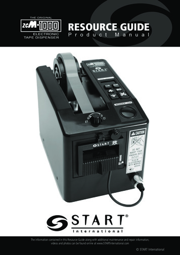
TO–92 EIA RADIAL TAPE IN FAN FOLD BOX OR ON REELH2AH2AH2BH2BHW2H4 H5T1L1H1W1 WLTT2F1F2P2P2P1DPFigure 1. Device Positioning on TapeSpecificationInchesSymbolS b e Feedhole DiameterD2Component Lead Thickness Dimension0.0150.0200.380.51Component Lead Pitch0.09450.1102.42.8F1, F2HBottom of Component to Seating PlaneH1Feedhole ection Left or Right00.0390H2BDeflection Front or Rear00.05101.00.70860.7681819.5H4Feedhole to Bottom of ComponentH5Feedhole to Seating Plane0.6100.64915.516.5LDefective Unit Clipped Dimension0.33460.4338.511L1Lead Wire Enclosure0.09842—2.5—PFeedhole Pitch0.49210.507912.512.9P1Feedhole Center to Center Lead0.23420.26585.956.75First Lead Spacing 0567—1.44P2TAdhesive Tape ThicknessT1Overall Taped Package ThicknessT2Carrier Strip Thickness0.0140.0270.350.65WCarrier Strip Width0.68890.748117.519W1Adhesive Tape Width0.21650.28415.56.3W2Adhesive Tape Position.00590.01968.150.5NOTES:1. Maximum alignment deviation between leads not to be greater than 0.2 mm.2. Defective components shall be clipped from the carrier tape such that the remaining protrusion (L) does not exceed a maximum of 11 mm.3. Component lead to tape adhesion must meet the pull test requirements established in Figures 5, 6 and 7.4. Maximum non–cumulative variation between tape feed holes shall not exceed 1 mm in 20 pitches.5. Holddown tape not to extend beyond the edge(s) of carrier tape and there shall be no exposure of adhesive.6. No more than 1 consecutive missing component is permitted.7. A tape trailer and leader, having at least three feed holes is required before the first and after the last component.8. Splices will not interfere with the sprocket feed holes.Tape and Reel Specifications5.12–8Motorola Master Selection Guide
TO–92 EIA RADIAL TAPE IN FAN FOLD BOX OR ON REELFAN FOLD BOX ÇÇÇÇÇÇADHESIVE TAPE ONTOP SIDEFLAT SIDEADHESIVE TAPE ONTOP SIDEROUNDED SIDECARRIERSTRIPCARRIERSTRIPFigure 2. Style M252 mm9.92”FLAT SIDE OF TRANSISTORAND ADHESIVE TAPE VISIBLE.Style M fan fold box is equivalent to styles E andF of reel pack dependent on feed orientation frombox.330 mm13”MAXROUNDED SIDE OF TRANSISTOR ANDADHESIVE TAPE VISIBLE.Style P fan fold box is equivalent to styles A andB of reel pack dependent on feed orientation frombox.Figure 3. Style PMAX58 mm2.28”MAXFigure 4. Fan Fold Box DimensionsADHESION PULL TESTS500 GRAM PULL FORCE70 GRAMPULL FORCE100 GRAMPULL FORCE16 mm16 mmHOLDINGFIXTUREThe component shall not pull free with a 300 gramload applied to the leads for 3 1 second.Figure 5. Test #1Motorola Master Selection GuideHOLDINGFIXTUREHOLDINGFIXTUREThe component shall not pull free with a 70 gramload applied to the leads for 3 1 second.Figure 6. Test #25.12–9There shall be no deviation in the leads andno component leads shall be pulled free ofthe tape with a 500 gram load applied to thecomponent body for 3 1 second.Figure 7. Test #3Tape and Reel Specifications
TO–92 EIA RADIAL TAPE IN FAN FOLD BOX OR ON REELREEL STYLESCORE DIA.82mm 1mmARBOR HOLE DIA.30.5mm 0.25mmMARKING NOTEHUB RECESS76.2mm 1mmRECESS DEPTH9.5mm MIN365mm 3, – 0mm38.1mm 1mm48 mmMAXMaterial used must not cause deterioration of components or degrade lead solderabilityFigure 8. Reel SpecificationsADHESIVE TAPE ON REVERSE SCARRIER STRIPCARRIER STRIPROUNDEDSIDEFLAT SIDEADHESIVE TAPEFEEDFEEDRounded side of transistor and adhesive tape visible.Flat side of transistor and carrier strip visible(adhesive tape on reverse side).Figure 9. Style AFigure 10. Style BADHESIVE TAPE ON REVERSECARRIER STRIPCARRIER STRIPFLAT SIDEROUNDEDSIDEADHESIVE TAPEFEEDFEEDFlat side of transistor and adhesive tape visible.Rounded side of transistor and carrier strip visible(adhesive tape on reverse side).Figure 11. Style ETape and Reel SpecificationsFigure 12. Style F5.12–10Motorola Master Selection Guide
DO–35, DO–41, Surmetic 30Radial Tape in Fan FoldBox or On ReelAXIALLEADED DEVICERADIALTAPE IN FANFOLD BOX ORON REELRadial tape in fan fold box or on reel for axial leaded devices is the bestmethod of capturing devices for automatic insertion in printed circuitboards. These methods of taping are compatible with various equipmentfor active and passive component insertion. Available in Fan Fold BoxAvailable on 365 mm ReelsAccommodates All Standard InsertersAllows Flexible Circuit Board Layout2.5 mm Pin Spacing for SolderingOrdering Notes:When ordering radial tape in fan fold box or on reel, specify the style perFigures 4 through 13. Add the appropriate suffix per Tables A and B aslisted below:Fan Fold Box Information — Minimum order quantity 1 Box/ 200LL.Order in increments of 3000.Reel Information — Minimum order quantity 1 Reel/ 200LL.Reel Information — Order in increments of 3000.CASE 299–02 (DO–35)CASE 059–03 (DO–41)BBDKCASE 059–01 (Surmetic 30)DKFBDEVICE TITLE SUFFIX DESIGNATOR TABLEDK–RR1 Euroform radial format and reeled per Figures 4, 6, 9, 10.Polarity band up with cathode lead off first.FAAF–RR2 Euroform radial format and reeled per Figures 4, 6, 9, 10.Polarity band down with anode lead off f
EIA 481, –1, –2 SOD–123, SC–59, SC–70/SOT–323, SC–70ML/SOT–363, SOT–23, SOT–143, TSOP–6, in 8 mm Tape SO–8, Micro8, OPTO SO–8, SOT–223, SMA, SMB in 12 mm Tape DPAK, PFP–16, SO–14, SO–16, SMC, TSSOP–16, TSSOP–20, 430 and 430B in 16 mm Tape D2PAK, D3PAK, 6–Pin Optoisolators in 24 mm Tape Use the standard device title and add the required .