Transcription
Installation Manualfor Cisco IPTVReceiversfor use with your AT&T U-verse TV serviceModel ISB7005
2
ContentsNotice for Installers . 4IMPORTANT SAFETY INSTRUCTIONS. 4Change the Way You Watch TV . 7What’s In the Carton? . 7Safety First . 7Identify Your Receiver with the Serial Number . 7In This Manual . 7Questions About Your Service. . 7Protecting You and the Environment . 7Front Panel . 8Back Panel . 9Connecting the Receiver .10ISB7005 Wireless Network Connection .11Connecting the Wireless Access Point to the Wireless Gateway . 12Pairing the Wireless Access Point and Receiver .12Connections for a High-Definition TV (HDTV) .13Connections for a Standard-Definition TV (SDTV) .14Connections for a VCR or DVD Recorder .15Connecting an Over-the-Air Converter Box.15Connecting to an HDTV with an HDMI Connector .16Connecting to an HDTV with a DVI Connector .17Connecting to an HDTV with Component (YPbPr) Connectors .18Connecting to an SDTV with Component (YPbPr) Connectors .19Connecting to an SDTV with an S-Video Connector.20Connecting to an SDTV with an RCA-Type Connector .21Connecting to an SDTV with a Coaxial Cable.22Connecting to a Home Theater System with Component (YPbPr) Connectors .23Connecting to a Stereo VCR or DVD Recorder (optional) .24Troubleshooting .25Avoid Screen Burn-In.25Frequently Asked Questions .26Picture Formats .27Index .28Compliance Information .303
Notice for InstallersThe servicing instructions in this notice are for use by qualified service personnel only. To reduce the risk ofelectric shock, do not perform any servicing other than that contained in the operating instructions, unless you arequalified to do so.Note to System InstallerFor this apparatus, the cable shield/screen shall be groundedas close as practical to the point of entry of the cable into thebuilding. For products sold in the US and Canada, thisreminder is provided to call the system installer's attention toArticle 800-93 and Article 800-100 of the NEC (or CanadianElectrical Code Part 1), which provides guidelines for propergrounding of the cable shield.CAUTION: To reduce the risk of electric shock, do notremove cover (or back). No user-serviceable partsinside. Refer servicing to qualified service personnel.WARNINGTO PREVENT FIRE OR ELECTRIC SHOCK, DO NOTEXPOSE THIS UNIT TO RAIN OR MOISTURE.This symbol is intended to alert you that uninsulated voltagewithin this product may have sufficient magnitude to causeelectric shock.Therefore, it is dangerous to make any kind ofcontact with any inside part of this product.Ce symbole a pour but d’alerter toute personne qu’un contactavec une pièce interne de ce produit, sous tension et nonisolée, pourrait être suffisant pour provoquer un chocélectrique. Il est donc dangereux d’être en contact avec toutepièce interne de ce produit.This symbol is intended to alert you of the presenceof important operating and maintenance (servicing)instructions in the literature accompanying this product.Ce symbole a pour but de vous avertir qu’unedocumentation importante sur le fonctionnement etl’entretien accompagne ce produit.20080814 Installer800IMPORTANT SAFETY INSTRUCTIONS1) Read these instructions.2) Keep these instructions.3) Heed all warnings.4) Follow all instructions.5) Do not use this apparatus near water.6) Clean only with dry cloth.7) Do not block any ventilation openings. Install inaccordance with the manufacturer’s instructions.8) Do not install near any heat sources such as radiators,heat registers, stoves, or other apparatus (includingamplifiers) that produce heat.9) Do not defeat the safety purpose of the polarized orgrounding-type plug. A polarized plug has two bladeswith one wider than the other. A grounding-type plug hastwo blades and a third grounding prong. The wide bladeor the third prong are provided for your safety. If theprovided plug does not fit into your outlet, consult anelectrician for replacement of the obsolete outlet.10) Protect the power cord from being walked on or pinchedparticularly at plugs, convenience receptacles, and thepoint where they exit from the apparatus.11) Only use attachments/accessories specified by themanufacturer.12)4Use only with the cart, stand, tripod, bracket, ortable specified by the manufacturer, or sold withthe apparatus. When a cart is used, use cautionwhen moving the cart/apparatus combination to avoidinjury from tip-over.13) Unplug this apparatus during lightning storms or whenunused for long periods of time.14) Refer all servicing to qualified service personnel.Servicing is required when the apparatus has beendamaged in any way, such as a power-supply cord or plugis damaged, liquid has been spilled or objects have falleninto the apparatus, the apparatus has been exposed torain or moisture, does not operate normally, or has beendropped.Power Source WarningA label on this product indicates the correct power source for thisproduct. Operate this product only from an electrical outlet withthe voltage and frequency indicated on the product label. If you areuncertain of the type of power supply to your home or business,consult your service provider or your local power company.The AC inlet on the unit must remain accessible and operable atall times.Ground the ProductWARNING: Avoid electric shock and fire hazard! If thisproduct connects to cable wiring, be sure the cable systemis grounded (earthed). Grounding provides some protectionagainst voltage surges and built-up static charges.Protect the Product from LightningIn addition to disconnecting the AC power from the wall outlet,disconnect the signal inputs.
IMPORTANT SAFETY INSTRUCTIONS, continuedVerify the Power Source from theOn/Off Power LightWhen the on/off power light is not illuminated, the apparatus maystill be connected to the power source. The light may go out whenthe apparatus is turned off, regardless of whether it is still pluggedinto an AC power source.Eliminate AC Power/Mains OverloadsService WarningsWARNING: Avoid electric shock! Do not openthe cover of this product. Opening or removing the covermay expose you to dangerous voltages. If you open thecover, your warranty will be void. This product containsno user-serviceable parts.Check Product SafetyWARNING: Avoid electric shock and fire hazard! Donot overload AC power/mains, outlets, extension cords, orintegral convenience receptacles. For products that requirebattery power or other power sources to operate them,refer to the operating instructions for those products.Provide Ventilation andSelect a LocationUpon completion of any service or repairs to this product, the servicetechnician must perform safety checks to determine that this productis in proper operating condition.Protect the Product When Moving ItAlways disconnect the power source when moving the apparatusor connecting or disconnecting cables.20110316 IP No Tuner Safety Remove all packaging material before applying power to theproduct. Do not place this apparatus on a bed, sofa, rug, or similarsurface. Do not place this apparatus on an unstable surface. Do not place this apparatus in excessive heat or moisture. Do not install this apparatus in an enclosure, such as abookcase or rack, unless the installation provides properventilation. Do not place entertainment devices (such as VCRs or DVDs),lamps, books, vases with liquids, or other objects on top of thisproduct. Do not block ventilation openings.Operating EnvironmentThis product is designed for operation indoors with a temperaturerange from 32 to 104 F (0 to 40 C). Each product should haveadequate spacing on all sides so that the cooling air vents on thechassis are not blocked.Protect from Exposure to Moistureand Foreign ObjectsWARNING: Avoid electric shock and fire hazard! Donot expose this product to dripping or splashing liquids,rain, or moisture. Objects filled with liquids, such as vases,should not be placed on this apparatus.WARNING: Avoid electric shock and fire hazard!Unplug this product before cleaning. Do not use a liquidcleaner or an aerosol cleaner. Do not use a magnetic/staticcleaning device (dust remover) to clean this product.WARNING: Avoid electric shock and fire hazard!Never push objects through the openings in this product.Foreign objects can cause electrical shorts that can resultin electric shock or fire.5
6
Change the Way You Watch TVWelcome to U-verse TV. The ISB7005 devices, known as U-verse receivers, bring a rich, new set ofinteractive services directly to you through your TV and your in-home IP network. The receiver useswireless technology 802.11n to connect to the network.The ISB7005 receiver allows for easy and secure connection to U-verse services. The signalstrength indicator on the front panel of the receiver identifies the strength of the wireless connectionand aids in the proper placement of the receiver.What’s In the Carton?In addition to this installation manual, the receiver carton contains the following items: An ISB7005 Receiver - A wireless receiver A power cord and power adapterTo support the wireless functionality of the ISB7005 receiver, you will also need a wirelessaccess point that is packaged separately from your receiver. See page 12 of this guide for moreinformation on the wireless access point.Safety FirstBefore using the receiver, read the Important Safety Instructions section of this manual.Identify Your Receiver with the Serial NumberAt times your service provider may ask for the serial number. To find the serial number for yourreceiver, look on the bottom of the receiver for the label. The serial number is a 9-digit numericcode to the right of the letters “S/N” on the label.Use the space provided here to record the serial number:In This ManualThis manual covers the information you need to connect your receiver to both your in-home IPnetwork and your entertainment system. The manual also outlines certain safeguards and installationinformation. The safety information contained in this manual was developed and provided solely bythe receiver manufacturer, Cisco Systems, Inc.Questions About Your ServiceFor questions about how to operate your receiver, once installed, refer to your Feature Guide availablefor download at: att.com/userguides. For all other questions about your TV service, contact yourservice provider.Protecting You and the EnvironmentCisco addresses the environmental impact of networking products throughout their lifecycle, from productdevelopment, manufacturing, and use to service and end-of-life. Integrating environmental policies intoCisco engineering and manufacturing practices results in socially accountable business practices thathelp reduce the environmental impact associated with networking products.7
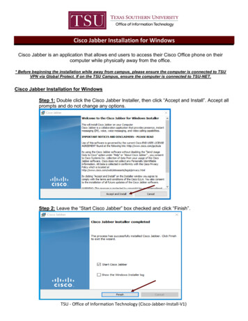
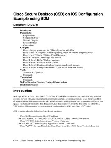
Front 8201 PowerTurns the receiver on or places it in standby. To restart the receiver,press and hold the POWER button for 10 seconds. The LED is green2 Model NumberIdentifies the model number of your receiver as ISB70053 Signal StrengthIndicatorIdentifies the strength of the wireless connection4 LinkIndicates network link status. The LED is green5 HDIndicates the set-top is set to a resolution of 720p, 1080i, or 1080p.The LED is blue6 RecordIndicates that a recording is in progress. The LED is red7 IR SensorReceives the infrared signal from the remote control. The sensor isbehind the front panel8 MenuAccesses the on-screen menu9 Arrow KeysAccesses on-screen services (such as the on-screen guide, video-ondemand, or pay-per-view) and navigates menus10 OKSelects the current item11 USB PortUSB connector. (Reserved for future use)Note: This illustration may vary from the actual product.89
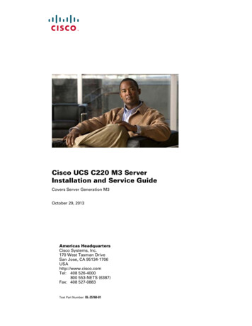
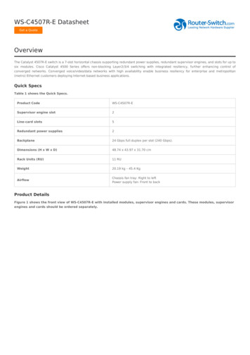
Back PanelPbYLRTO TV(VIDEO AL45678USBPOWER9101 To TV (Video Out)Connect to TV. You must set the channel on your TV to the channeldesignated by your service provider (usually channel 3). Contact yourservice provider for the channel information2 NetworkConnect to the Ethernet (CAT-5) network at your home, if applicable3 YPbPrConnect the receiver to the component video input (YPbPr) on theHDTV. See pages 13 and 14 for more information4 S-VideoConnect an S-Video cable to send an S-Video signal to your TV, VCR, orDVD recorder. This signal is standard-definition but higher quality thanother standard-definition TV connections. See page 14 for moreinformation5 Video OutConnect to composite input on your HDTV or SDTVNote: Two video output connectors are provided. Typically, one outputis connected to the TV, and the other output is used to connect to ahome theater system, DVD recorder, or VCR6 Audio Out (L/R)Connect RCA-type cables to Audio Out to send analog audio signals(left and right) to a TV with stereo inputs or to a stereo amplifierNote: Two sets of audio out connectors are provided. Typically, one setof outputs is connected to the TV, and the other set is used to connectto a home theater system, DVD recorder, or VCR7 OpticalConnect an optical cable to send a digital audio signal to a surroundsound receiver or other digital audio device8 HDMIConnect an HDTV HDMI (High-Definition Multimedia Interface) cablefrom the HDTV to the HDMI port. HDMI supports both digital audio andvideo. See page 13 for more information9 USB PortUSB connector. (Reserved for future use)10 PowerConnect the DC output of the AC power adapter (provided) to deliverpower to the receiverNote: This illustration may vary from the actual product.9
Connecting the ReceiverTo connect your receiver to your network and home entertainment devices, complete these steps.1Because the connectionsfor a high-definition (HD)164or standard-definition (SD)93orTV are different, you mustdetermine if your TV is HDor SD. Your TV mustreceive HD signals foryou to enjoy the benefitsof HDTV. Refer to the manual that came with your TV for more information.See page 27 for more information on picture formats.Make the connections for your TV, VCR, and DVD recorder as follows:2 3 If you are using an HDTV, see page 13 and the connection diagrams in thismanual. If you are using a standard-definition TV, see page 14 and the connectiondiagrams in this manual. If you want to record some programs on VCR tape or DVD, see page 15and the connection diagrams in this manual.Identify the additional consumerelectronic devices you willconnect to the receiver and TV.See pages 16 through 24 andrefer to the owner’s manual forthe device.VCRDVDOtherHome TheaterPlug the receiver and the TV into an AC power source that is not controlled by aswitch. For further instructions on completing your setup, refer to the FeatureGuide available from your service provider.410
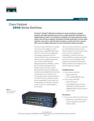
ISB7005 Wireless NetworkConnectionThe ISB7005 receiver allows for easy and secureconnection to U-verse services. The signal strengthindicator on the front panel of the receiver identifiesthe strength of the wireless connection and aids in theproper placement of the receiver.POWERLINKHDISB7005Signal Strength IndicatorT14822 You cannot change the brightness of the signalstrength indicator. The receiver must be paired with the wireless access point for the wireless connection to beestablished. See page 12 for more information.WirelessLEDsReceiver Operational StatusThis indicates the wireless signal is excellent. The video quality is good.This indicates the wireless signal is very good. The video quality is good.This indicates the wireless signal is good. The video quality is good. You must obtainthree or more green bars at initial installation.This indicates the wireless signal is fair. The video quality is good.This indicates the wireless signal is weak. The video quality may be poor. The STBshould be re-oriented to achieve a better wireless signal.This indicates the wireless signal is very weak. No video can be displayed. Thereceiver must be re-oriented to achieve a better wireless signal.This indicates no wireless connectivity.11
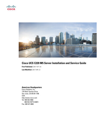
Connecting the Wireless Access Point to the WirelessGatewayRJ-45Cable1. Connect the 12 VDC Power Supplyplug on the access point to the wallpower outlet. Use only the poweradapter provided with the product.Reset2. Connect the power plug to the powerreceptacle on the wireless access point.Ethernet3. Connect one end of the RJ-45Ethernet cable to the Ethernet port onthe wireless access point.4. Connect the other end of the RJ-45Ethernet cable to an available Ethernetport on your wireless gateway.WirelessGatewayEthernet PortReset12VDC12VDCTo Wall Power OutletPower Receptacle1Wireless LED12Wi-Fi Protected Setup (WPS) button2343Wi-Fi Protected Setup (WPS) LED4Ethernet LED5Power LEDT149615T14853Note: This illustration may vary from the actual product.1Ethernet PortConnects the Wireless Access Point to awireless gateway2ResetRestores factory default settings when heldfor more than 5 seconds3PowerConnects device to the external 12 VDCpower supplyEthernet1Reset23Note: This illustration may vary from the actual product.12VDCT14854Pairing the Wireless Access Point and Receiver1. Press the OK button on the receiver.2. Press the WPS button on the wireless access point.12
Connections for a High-Definition TV (HDTV)To use the receiver with an HDTV, you must make one of the following connections to view the HDcontent. Refer to the owner’s manual for your TV and the cabling diagrams in this manual for moredetailed connection information.Although all connections
In addition to this installation manual, the receiver carton contains the following items: An ISB7005 Receiver - A wireless receiver A power cord and power adapter To support the wireless functionality of the ISB7005 receiver, you will also need a wireless access File Size: 2MB