Transcription
Cisco UCS C220 M5 Server Installation and Service GuideFirst Published: 2017-07-14Last Modified: 2017-09-12Americas HeadquartersCisco Systems, Inc.170 West Tasman DriveSan Jose, CA 95134-1706USAhttp://www.cisco.comTel: 408 526-4000800 553-NETS (6387)Fax: 408 527-0883
THE SPECIFICATIONS AND INFORMATION REGARDING THE PRODUCTS IN THIS MANUAL ARE SUBJECT TO CHANGE WITHOUT NOTICE. ALL STATEMENTS,INFORMATION, AND RECOMMENDATIONS IN THIS MANUAL ARE BELIEVED TO BE ACCURATE BUT ARE PRESENTED WITHOUT WARRANTY OF ANY KIND,EXPRESS OR IMPLIED. USERS MUST TAKE FULL RESPONSIBILITY FOR THEIR APPLICATION OF ANY PRODUCTS.THE SOFTWARE LICENSE AND LIMITED WARRANTY FOR THE ACCOMPANYING PRODUCT ARE SET FORTH IN THE INFORMATION PACKET THAT SHIPPED WITHTHE PRODUCT AND ARE INCORPORATED HEREIN BY THIS REFERENCE. IF YOU ARE UNABLE TO LOCATE THE SOFTWARE LICENSE OR LIMITED WARRANTY,CONTACT YOUR CISCO REPRESENTATIVE FOR A COPY.The following information is for FCC compliance of Class A devices: This equipment has been tested and found to comply with the limits for a Class A digital device, pursuant to part 15of the FCC rules. These limits are designed to provide reasonable protection against harmful interference when the equipment is operated in a commercial environment. This equipmentgenerates, uses, and can radiate radio-frequency energy and, if not installed and used in accordance with the instruction manual, may cause harmful interference to radio communications.Operation of this equipment in a residential area is likely to cause harmful interference, in which case users will be required to correct the interference at their own expense.The following information is for FCC compliance of Class B devices: This equipment has been tested and found to comply with the limits for a Class B digital device, pursuant to part 15of the FCC rules. These limits are designed to provide reasonable protection against harmful interference in a residential installation. This equipment generates, uses and can radiate radiofrequency energy and, if not installed and used in accordance with the instructions, may cause harmful interference to radio communications. However, there is no guarantee that interferencewill not occur in a particular installation. If the equipment causes interference to radio or television reception, which can be determined by turning the equipment off and on, users areencouraged to try to correct the interference by using one or more of the following measures: Reorient or relocate the receiving antenna. Increase the separation between the equipment and receiver. Connect the equipment into an outlet on a circuit different from that to which the receiver is connected. Consult the dealer or an experienced radio/TV technician for help.Modifications to this product not authorized by Cisco could void the FCC approval and negate your authority to operate the productThe Cisco implementation of TCP header compression is an adaptation of a program developed by the University of California, Berkeley (UCB) as part of UCB’s public domain versionof the UNIX operating system. All rights reserved. Copyright 1981, Regents of the University of California.NOTWITHSTANDING ANY OTHER WARRANTY HEREIN, ALL DOCUMENT FILES AND SOFTWARE OF THESE SUPPLIERS ARE PROVIDED "AS IS" WITH ALL FAULTS.CISCO AND THE ABOVE-NAMED SUPPLIERS DISCLAIM ALL WARRANTIES, EXPRESSED OR IMPLIED, INCLUDING, WITHOUT LIMITATION, THOSE OFMERCHANTABILITY, FITNESS FOR A PARTICULAR PURPOSE AND NONINFRINGEMENT OR ARISING FROM A COURSE OF DEALING, USAGE, OR TRADE PRACTICE.IN NO EVENT SHALL CISCO OR ITS SUPPLIERS BE LIABLE FOR ANY INDIRECT, SPECIAL, CONSEQUENTIAL, OR INCIDENTAL DAMAGES, INCLUDING, WITHOUTLIMITATION, LOST PROFITS OR LOSS OR DAMAGE TO DATA ARISING OUT OF THE USE OR INABILITY TO USE THIS MANUAL, EVEN IF CISCO OR ITS SUPPLIERSHAVE BEEN ADVISED OF THE POSSIBILITY OF SUCH DAMAGES.Any Internet Protocol (IP) addresses and phone numbers used in this document are not intended to be actual addresses and phone numbers. Any examples, command display output, networktopology diagrams, and other figures included in the document are shown for illustrative purposes only. Any use of actual IP addresses or phone numbers in illustrative content is unintentionaland coincidental.Cisco and the Cisco logo are trademarks or registered trademarks of Cisco and/or its affiliates in the U.S. and other countries. To view a list of Cisco trademarks, go to this URL: http://www.cisco.com/go/trademarks. Third-party trademarks mentioned are the property of their respective owners. The use of the word partner does not imply a partnershiprelationship between Cisco and any other company. (1110R) 2017Cisco Systems, Inc. All rights reserved.
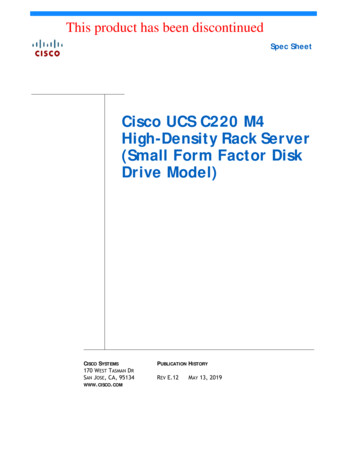
CHAPTER1Overview Overview, page 1 External Features, page 1 Serviceable Component Locations, page 5 Summary of Server Features, page 6OverviewThe server is orderable in different versions, each with a different front panel/drive-backplane configuration. Cisco UCS C220 M5 (UCSC-220-M5SX)—Small form-factor (SFF) drives, with 10-drive backplane.Supports up to 10 2.5-inch SAS/SATA drives. Drive bays 1 and 2 support NVMe SSDs. Cisco UCS C220 M5 (UCSC-220-M5L)—Large form-factor (LFF) drives, with four-drive backplane.Supports up to four 3.5-inch SAS/SATA drives. Drive bays 1 and 2 support NVMe SSDs. A size-converterdrive sled is required to hold 2.5-inch SSDs.External FeaturesThis topic shows the external features of the server versions.Cisco UCS C220 M5 Server (SFF Drives) Front Panel FeaturesThe following figure shows the front panel features of the small form-factor drive versions of the server.Cisco UCS C220 M5 Server Installation and Service Guide1
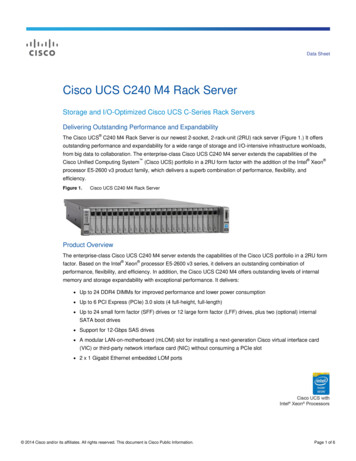
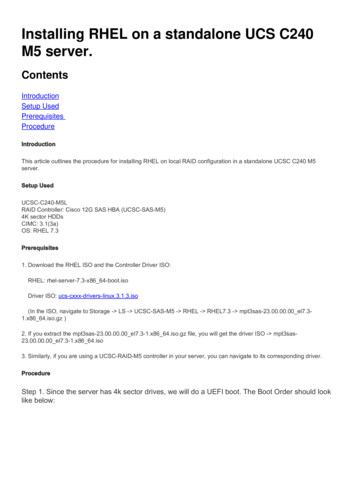
OverviewExternal FeaturesFor definitions of LED states, see Front-Panel LEDs, on page 25.Figure 1: Cisco UCS C220 M5 Server (SFF Drives) Front PanelDrive bays 1 – 10 support SAS/SATA hard disk drives(HDDs) and solid state drives (SSDs)12 UCSC-220-M5SX: Drive bays 1 and 2 supportNVMe PCIe SSDs.7Fan status LED8Network link activity LED 3Power button/power status LED9Temperature status LED4Unit identification button/LED10Pull-out asset tag5System status LED11KVM connector(used with KVM cable that provides one DB-15 VGA, oneDB-9 serial, and two USB connectors)Power supply status LED6-Cisco UCS C220 M5 Server (LFF Drives) Front Panel FeaturesThe following figure shows the front panel features of the large form-factor drive version of the server.Cisco UCS C220 M5 Server Installation and Service Guide2
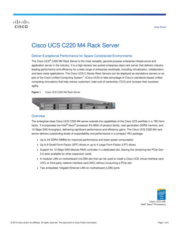
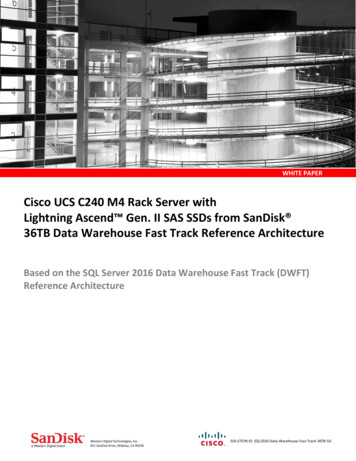
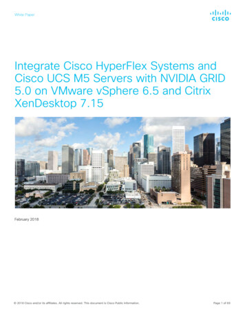
OverviewExternal FeaturesFor definitions of LED states, see Front-Panel LEDs, on page 25.Figure 2: Cisco UCS C220 M5 Server (LFF Drives) Front Panel1Drive bays 1 – 4 support SAS/SATA HDDs and SSDs7Temperature status LED2Drive bays 1 and 2 support NVMe PCIe SSDs.8Power supply status LEDA size-converter drive sled is required if 2.5-inch SSDsare used.3Power button/power status LED9Network link activity LED4Unit identification button/LED10KVM connector(used with KVM cable that provides one DB-15 VGA, oneDB-9 serial, and two USB connectors)5System health LED116Fan status LED-Pull-out asset tagCisco UCS C220 M5 Server Rear Panel FeaturesThe rear panel features are the same for all versions of the server.Cisco UCS C220 M5 Server Installation and Service Guide3
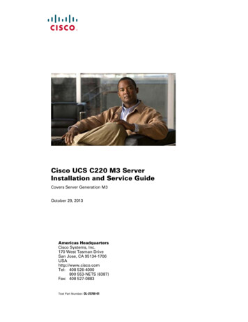
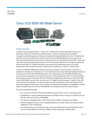
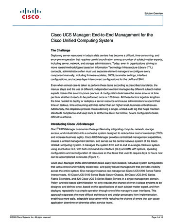
OverviewExternal FeaturesFor definitions of LED states, see Rear-Panel LEDs, on page 28.Figure 3: Cisco UCS C220 M5 Server Rear Panel1Modular LAN-on-motherboard (mLOM) card bay (x16 7PCIe lane)Rear unit identification button/LED2USB 3.0 ports (two)8Power supplies (two, redundant as 1 1)3Dual 1-Gb/10-Gb Ethernet ports (LAN1 and LAN2)9PCIe riser 2/slot 2 (x16 lane)The dual LAN ports can support 1 Gbps and 10 Gbps,depending on the link partner capability.Includes PCIe cable connectors for front-loading NVMeSSDs (x8 lane)4VGA video port (DB-15 connector)10PCIe riser 1/slot 1 (x16 lane)51-Gb Ethernet dedicated management port11Threaded holes for dual-hole grounding lug6Serial port (RJ-45 connector)-Cisco UCS C220 M5 Server Installation and Service Guide4
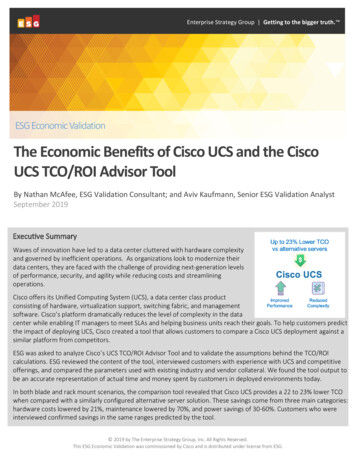
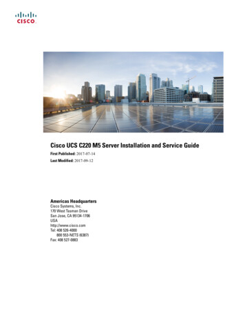
OverviewServiceable Component LocationsServiceable Component LocationsThis topic shows the locations of the field-replaceable components and service-related items. The view in thefollowing figure shows the server with the top cover removed.Figure 4: Cisco UCS C220 M5 Server, Serviceable Component Locations1Front-loading drive bays 1–10 support SAS/SATAdrives.10Power supplies (hot-swappable when redundant as 1 1) UCSC-220-M5SX: Drive bays 1 and 2 supportNVMe PCIe SSDs. UCSC-220-M5L: Drive bays 1 and 2 supportNVMe PCIe SSDs.2Cooling fan modules (seven, hot-swappable)11Trusted platform module (TPM) socket on motherboard(not visible in this view)3Supercap unit mounting bracket (RAID backup)12PCIe riser 2/slot 2 (half-height, x16 lane)Includes PCIe cable connectors for front-loading NVMeSSDs (x8 lane)Cisco UCS C220 M5 Server Installation and Service Guide5
OverviewSummary of Server FeaturesDIMM sockets on motherboard (12 per CPU)413PCIe riser 1/slot 1 (full-height, x16 lane)Includes socket for Micro-SD card5CPUs and heatsinks (up to two)14Modular LOM (mLOM) card bay on chassis floor (x16PCIe lane), not visible in this view6Mini storage module socket15Modular RAID (mRAID) riser, can optionally be a riserthat supports either:Supports either an SD card module with two SD cardslots; or an M.2 module with two NVMe or SATA M.2SSD slots. Hardware RAID controller card Interposer card for embedded SATA RAID7Chassis intrusion switch (optional)16PCIe cable connectors for front-loading NVMe SSDs onPCIe riser 28Internal USB 3.0 port on motherboard17Micro-SD card socket on PCIe riser 19RTC battery, vertical socket-The Technical Specifications Sheets for all versions of this server, which include supported component partnumbers, are at Cisco UCS Servers Technical Specifications Sheets (scroll down to Technical Specifications).Summary of Server FeaturesThe following table lists a summary of server features.FeatureDescriptionChassisOne rack-unit (1RU) chassisCentral ProcessorUp to two CPUs from the Intel Xeon Processor Scalable Family. This includes CPUs fromthe following series: Intel Xeon Bronze 3XXX Processors Intel Xeon Silver 4XXX Processors Intel Xeon Gold 5XXX Processors Intel Xeon Gold 6XXX Processors Intel Xeon Platinum 8XXX ProcessorsMemory24 DDR4 DIMM sockets on the motherboard (12 each CPU)Multi-bit error protectionMulti-bit error protection is supportedCisco UCS C220 M5 Server Installation and Service Guide6
OverviewSummary of Server FeaturesFeatureDescriptionBaseboard managementBMC, running Cisco Integrated Management Controller (Cisco IMC) firmware.Depending on your Cisco IMC settings, Cisco IMC can be accessed through the 1-Gb dedicatedmanagement port, the 1-Gb/10-Gb Ethernet LAN ports, or a Cisco virtual interface card.Network and management I/ORear panel: One 1-Gb Ethernet dedicated management port (RJ-45 connector) Two 1-Gb/10-Gb BASE-T Ethernet LAN ports (RJ-45 connectors)The dual LAN ports can support 1 Gbps and 10 Gbps, depending on the link partnercapability. One RS-232 serial port (RJ-45 connector) One VGA video connector port (DB-15 connector) Two USB 3.0 portsFront panel: One front-panel keyboard/video/mouse (KVM) connector that is used with the KVMcable, which provides two USB 2.0, one VGA, and one DB-9 serial connector.Modular LOMOne dedicated socket (x16 PCIe lane) that can be used to add an mLOM card for additionalrear-panel connectivity.WoLThe two 1-Gb/10-Gb BASE-T Ethernet LAN ports support the wake-on-LAN (WoL) standard.PowerTwo power supplies, redundant as 1 1: AC power supplies 770 W AC each AC power supplies 1050 W AC each DC power supplies 1050 W DC eachDo not mix power supply types or wattages in the server.ACPIThe advanced configuration and power interface (ACPI) 4.0 standard is supported.CoolingSeven hot-swappable fan modules for front-to-rear cooling.PCIe I/OTwo horizontal PCIe expansion slots on a PCIe riser assembly.See PCIe Slot Specifications, on page 71 for specifications of the slots.InfiniBandThe PCIe bus slots in this server support the InfiniBand architecture.Cisco UCS C220 M5 Server Installation and Service Guide7
OverviewSummary of Server FeaturesFeatureDescriptionStorage, front-panelThe server is orderable in three different versions, each with a different frontpanel/drive-backplane configuration. Cisco UCS C220 M5 (UCSC-220-M5SX)—Small form-factor (SFF) drives, with 10-drivebackplane. Supports up to 10 2.5-inch SAS/SATA drives. Drive bays 1 and 2 supportNVMe SSDs. Cisco UCS C220 M5 (UCSC-220-M5L)—Large form-factor (LFF) drives, with four-drivebackplane. Supports up to four 3.5-inch SAS/SATA drives. Drive bays 1 and 2 supportNVMe SSDs. A size-converter drive sled is required to hold 2.5-inch SSDs.Storage, internalThe server has these internal storage options: One USB port on the motherboard. Mini-storage module socket, optionally with either: SD card module. Supports up to two SD cards. M.2 SSD module. Supports either two SATA M.2 SSDs or two NVMe M.2 SSDs. One micro-SD card socket on PCIe riser 1.Storage managementThe server has a dedicated internal mRAID riser that supports one of the followingstorage-controller options: A PCIe-style Cisco modular RAID controller card (SAS/SATA). A PCIe-style interposer card for the server’s embedded SATA RAID controller.For a detailed list of storage controller options, see Supported Storage Controllers and Cables,on page 105.RAID backupThe server has a mounting bracket near the cooling fans for the supercap unit that is used withthe Cisco modular RAID controller card.Integrated videoIntegrated VGA video.Cisco UCS C220 M5 Server Installation and Service Guide8
CHAPTER2Installing the Server Preparing for Installation, page 9 Installing the Server in a Rack, page 12 Initial Server Setup, page 17 NIC Mode and NIC Redundancy Settings, page 21 Updating the BIOS and Cisco IMC Firmware, page 22 Accessing the System BIOS, page 23 Smart Access Serial, page 23 Smart Access USB, page 24Preparing for InstallationThis section contains the following topics:Installation Warnings and GuidelinesNoteBefore you install, operate, or service a server, review the Regulatory Compliance and Safety Informationfor Cisco UCS C-Series Servers for important safety information.Cisco UCS C220 M5 Server Installation and Service Guide9
Installing the ServerInstallation Warnings and GuidelinesWarningIMPORTANT SAFETY INSTRUCTIONSThis warning symbol means danger. You are in a situation that could cause bodily injury. Beforeyou work on any equipment, be aware of the hazards involved with electrical circuitry and befamiliar with standard practices for preventing accidents. Use the statement number provided atthe end of each warning to locate its translation in the translated safety warnings that accompaniedthis device.Statement 1071WarningTo prevent the system from overheating, do not operate it in an area that exceeds the maximumrecommended ambient temperature of: 35 C (95 F).Statement 1047WarningThe plug-socket combination must be accessible at all times, because it serves as the maindisconnecting device.Statement 1019WarningThis product relies on the building’s installation for short-circuit (overcurrent) protection. Ensurethat the protective device is rated not greater than: 250 V, 15 A.Statement 1005WarningInstallation of the equipment must comply with local and national electrical codes.Statement 1074WarningThis unit is intended for installation in restricted access areas. A restricted access area can beaccessed only through the use of a special tool, lock, and key, or other means of security.Statement 1017CautionTo ensure proper airflow it is necessary to rack the servers using rail kits. Physically placing the units ontop of one another or “stacking” without the use of the rail kits blocks the air vents on top of the servers,which could result in overheating, higher fan speeds, and higher power consumption. We recommend thatyou mount your servers on rail kits when you are installing them into the rack because these rails providethe minimal spacing required between the servers. No additional spacing between the servers is requiredwhen you mount the units using rail kits.Cisco UCS C220 M5 Server Installation and Service Guide10
Installing the ServerRack RequirementsCautionAvoid uninterruptible power supply (UPS) types that use ferroresonant technology. These UPS types canbecome unstable with systems such as the Cisco UCS, which can have substantial current draw fluctuationsfrom fluctuating data traffic patterns.When you are installing a server, use the following guidelines: Plan your site configuration and prepare the site before installing the server. See the Cisco UCS SitePreparation Guide for the recommended site planning tasks. Ensure that there is adequate space around the server to allow for accessing the server and for adequateairflow. The airflow in this server is from front to back. Ensure that the air-conditioning meets the thermal requirements listed in the Environmental Specifications,on page 98. Ensure that the cabinet or rack meets the requirements listed in the Rack Requirements, on page 11. Ensure that the site power meets the power requirements listed in the Power Specifications, on page98. If available, you can use an uninterruptible power supply (UPS) to protect against power failures.Rack RequirementsThe rack must be of the following type: A standard 19-in. (48.3-cm) wide, four-post EIA rack, with mounting posts that conform to Englishuniversal hole spacing, per section 1 of ANSI/EIA-310-D-1992. The rack-post holes can be square 0.38-inch (9.6 mm), round 0.28-inch (7.1 mm), #12-24 UNC, or#10-32 UNC when you use the Cisco-supplied slide rails. The minimum vertical rack space per server must be one rack unit (RU), equal to 1.75 in. (44.45 mm).Supported Cisco Slide Rail KitsThe server supports the following rail kit options: Cisco part UCSC-RAILB-M4 (ball-bearing slide rail kit) Cisco part UCSC-RAILF-M4 (friction slide rail kit) Cisco part UCSC-CMAF-M4 (cable management arm)Rack Installation Tools RequiredThe slide rails sold by Cisco Systems for this server do not require tools for installation.Slide Rail and Cable Management Arm DimensionsThe slide rails for this server have an adjustment range of 24 to 36 inches (610 to 914 mm).The optional cable management arm (CMA) adds additional length requirements: The additional distance from the rear of the server to the rear of the CMA is 5.4 inches (137.4 mm). The total length of the server including the CMA is 35.2 inches (894 mm).Cisco UCS C220 M5 Server Installation and Service Guide11
Installing the ServerInstalling the Server in a RackInstalling the Server in a RackWarningTo prevent bodily injury when mounting or servicing this unit in a rack, you must take specialprecautions to ensure that the system remains stable. The following guidelines are provided to ensureyour safety:This unit should be mounted at the bottom of the rack if it is the only unit in the rack.When mounting this unit in a partially filled rack, load the rack from the bottom to the top withthe heaviest component at the bottom of the rack.If the rack is provided with stabilizing devices, install the stabilizers before mounting or servicingthe unit in the rack.Statement 1006Step 1Attach the inner rails to the sides of the server:a) Align an inner rail with one side of the server so that the three keyed slots in the rail align with the three pegs on theside of the server.b) Set the keyed slots over the pegs, and then slide the rail toward the front to lock it in place on the pegs. The front slothas a metal clip that locks over the front peg.c) Install the second inner rail to the opposite side of the server.Figure 5: Attaching the Inner Rail to the Side of the Server1Step 2Front of serverLocking clip on front of inner railOpen the front securing plate on
Cisco UCS C220 M5 Server Installation and Service Guide First Published: 2017-07-14 Last Modified: 2017-09-12 Americas Headquarters