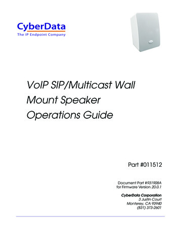
Transcription
The IP Endpoint CompanyVoIP SIP/Multicast WallMount Speaker Operations GuidePart #011512Document Part #931908Afor Firmware Version 20.0.1CyberData Corporation3 Justin CourtMonterey, CA 93940(831) 373-2601
VoIP SIP/Multicast Wall Mount Speaker Operations Guide 931908A Part # 011512 COPYRIGHT NOTICE: 2022, CyberData Corporation, ALL RIGHTS RESERVED.This manual and related materials are the copyrighted property of CyberData Corporation. No part ofthis manual or related materials may be reproduced or transmitted, in any form or by any means(except for internal use by licensed customers), without prior express written permission ofCyberData Corporation. This manual, and the products, software, firmware, and/or hardwaredescribed in this manual are the property of CyberData Corporation, provided under the terms of anagreement between CyberData Corporation and recipient of this manual, and their use is subject tothat agreement and its terms.DISCLAIMER: Except as expressly and specifically stated in a written agreement executed byCyberData Corporation, CyberData Corporation makes no representation or warranty, express orimplied, including any warranty or merchantability or fitness for any purpose, with respect to thismanual or the products, software, firmware, and/or hardware described herein, and CyberDataCorporation assumes no liability for damages or claims resulting from any use of this manual or suchproducts, software, firmware, and/or hardware. CyberData Corporation reserves the right to makechanges, without notice, to this manual and to any such product, software, firmware, and/orhardware.OPEN SOURCE STATEMENT: Certain software components included in CyberData products aresubject to the GNU General Public License (GPL) and Lesser GNU General Public License (LGPL)“open source” or “free software” licenses. Some of this Open Source Software may be owned by thirdparties. Open Source Software is not subject to the terms and conditions of the CyberDataCOPYRIGHT NOTICE or software licenses. Your right to copy, modify, and distribute any OpenSource Software is determined by the terms of the GPL, LGPL, or third party, according to wholicenses that software.Software or firmware developed by CyberData that is unrelated to Open Source Software iscopyrighted by CyberData, subject to the terms of CyberData licenses, and may not be copied,modified, reverse-engineered, or otherwise altered without explicit written permission fromCyberData Corporation.TRADEMARK NOTICE: CyberData Corporation and the CyberData Corporation logos aretrademarks of CyberData Corporation. Other product names, trademarks, and service marks may bethe trademarks or registered trademarks of their respective owners.Technical Support The IP Endpoint Company The fastest way to get technical support for your VoIP product is tosubmit a VoIP Technical Support form at the following website: http://support.cyberdata.net/ Phone: (831) 373-2601, Ext. 333 Email: support@cyberdata.net Fax: (831) 373-4193 Company and product information is at www.cyberdata.net.Operations Guide931908ACyberData Corporation
Revision InformationRevision 931908A, which corresponds to firmware version 20.0.1, was released on February 23,2022.Pictorial Alert IconsGENERAL ALERTGeneral AlertThis pictoral alert indicates a potentially hazardous situation. This alert will befollowed by a hazard level heading and more specific information about thehazard.GroundThis pictoral alert indicates the Earth grounding connection point.Hazard LevelsDanger: Indicates an imminently hazardous situation which, if not avoided, will result in death orserious injury. This is limited to the most extreme situations.Warning: Indicates a potentially hazardous situation which, if not avoided, could result in death orserious injury.Caution: Indicates a potentially hazardous situation which, if not avoided, could result in minor ormoderate injury. It may also alert users against unsafe practices.Notice: Indicates a statement of company policy (that is, a safety policy or protection of property).The safety guidelines for the equipment in this manual do not purport to address all the safety issuesof the equipment. It is the responsibility of the user to establish appropriate safety, ergonomic, andhealth practices and determine the applicability of regulatory limitations prior to use. Potential safetyhazards are identified in this manual through the use of words Danger, Warning, and Caution, thespecific hazard type, and pictorial alert icons.Operations Guide931908ACyberData Corporation
Important Safety Instructions1. Read these instructions.2. Keep these instructions.3. Heed all warnings.4. Follow all instructions.5. Do not use this apparatus near water.6. Clean only with dry cloth.7. Do not block any ventilation openings. Install in accordance with the manufacturer’s instructions.8. Do not install near any heat sources such as radiators, heat registers, stoves, or other apparatus(including amplifiers) that produce heat.9. Do not defeat the safety purpose of the polarized or grounding-type plug. A polarized plug hastwo blades with one wider than the other. A grounding type plug has two blades and a thirdgrounding prong. The wide blade or the third prong are provided for your safety. If the providedplug does not fit into your outlet, consult an electrician for replacement of the obsolete outlet.10. Protect the power cord from being walked on or pinched particularly at plugs, conveniencereceptacles, and the point where they exit from the apparatus.11. Only use attachments/accessories specified by the manufacturer.12. Refer all servicing to qualified service personnel. Servicing is required when the apparatus hasbeen damaged in any way, such as power-supply cord or plug is damaged, liquid has beenspilled or objects have fallen into the apparatus, the apparatus has been exposed to rain ormoisture, does not operate normally, or has been dropped.13. Prior to installation, consult local building and electrical code requirements.14. WARNING: The VoIP SIP/Multicast Wall Mount Speaker enclosure is not rated for any ACvoltages!WarningElectrical Hazard: This product should be installed by a licensed electricianaccording to all local electrical and building codes.GENERAL ALERTWarningElectrical Hazard: To prevent injury, this apparatus must be securely attached tothe floor/wall in accordance with the installation instructions.GENERAL ALERTWarningThe PoE connector is intended for intra-building connections only and does notroute to the outside plant.GENERAL ALERTOperations Guide931908ACyberData Corporation
Abbreviations and TermsOperations GuideAbbreviation or TermDefinitionA-lawA standard companding algorithm, used in European digitalcommunications systems to optimize, i.e., modify, the dynamic range of ananalog signal for digitizing.AVPAudio Video ProfileCat 5TIA/EIA-568-B Category 5DHCPDynamic Host Configuration ProtocolLANLocal Area NetworkLEDLight Emitting DiodeMbpsMegabits per Second.NTPNetwork Time ProtocolPBXPrivate Branch ExchangePoEPower over Ethernet (as per IEEE 802.3af standard)RTFMReset Test Function ManagementSIPSession Initiated ProtocolSRTPSecure Real Time Protocolu-lawA companding algorithm, primarily used in the digital telecommunicationUCUnified CommunicationsVoIPVoice over Internet Protocol931908ACyberData Corporation
ContentsiChapter 1 Product Overview11.1 How to Identify This Product .11.2 Typical Configuration .21.3 Product Features .31.4 Supported Protocols .41.5 Product Specifications .51.6 Compliance .61.6.1 CE Statement .61.6.2 FCC Statement .61.6.3 Industry Canada (IC) Compliance Statement .6Chapter 2 Installing the VoIP SIP/Multicast Wall Mount Speaker72.1 Parts List .72.2 Device Configuration .82.2.1 Connect Power to the Speaker .92.2.2 Confirm that the Speaker is Operational and Linked to the Network .112.2.3 Confirm the IP Address and Test the Audio .122.2.4 How to Set the Factory Default Settings .132.3.1 Factory Default Settings .142.3.2 VoIP SIP/Multicast Wall Mount Speaker Web Page Navigation .152.3.3 Using the Toggle Help Button .162.3.4 Log in to the Configuration Home Page .182.3.5 Configure the Device .222.3.6 Configure the Network Parameters .242.3.7 Configure the SIP Parameters .272.3.8 Configure the SSL Parameters .332.3.9 Configure the Multicast Parameters .392.3.10 Configure the Audio Configuration Parameters .412.3.11 Configure the Events Parameters .462.3.12 Configure the Autoprovisioning Parameters .512.4.1 Downloading the Firmware .622.4.2 Reboot the Device .652.5.1 Command Interface Post Commands .66Appendix A Mounting the Speaker68A.1 Mounting .68A.2 Dimensions .69Appendix C Setting up a TFTP Server70C.1 Set up a TFTP Server .70C.1.1 Autoprovisioning requires a TFTP server for hosting the configuration file. .70C.1.2 In a LINUX Environment .70C.1.3 In a Windows Environment .70Appendix C Troubleshooting/Technical Support71C.1 Frequently Asked Questions (FAQ) .71C.2 Documentation .71C.3 Contact Information .72C.4 Warranty and RMA Information .72IndexOperations Guide73931908ACyberData Corporation
11 Product Overview1.1 How to Identify This ProductTo identify the VoIP SIP/Multicast Wall Mount Speaker, look for a model number label similar to theone shown in Figure 1-1. The model number on the label should be 011512.Figure 1-1. Model Number Labelwww.cyberdata.netVoIP SIP/Multicast Wall Mount Speaker011512* / 021538C*512000001512000001CAN ICES-3 (A)/NMB-3(A)00:20:F7:03:83:CAV 20.0.1This device complies with part 15 of the FCC Rules. Operation is subject to the following two conditions: (1) this device may not cause harmful interference, and (2) this device must accept any interference received, including interference that may cause undesired operation.Model numberOperations GuideSerial number begins with 512931908ACyberData Corporation
Product Overview 2Typical Configuration1.2 Typical ConfigurationFigure 1-2 shows a typical configuration for the VoIP SIP/Multicast Wall Mount Speaker.Figure 1-2. Typical IP Speaker ConfigurationOperations Guide931908ACyberData Corporation
Product Overview 3Product Features1.3 Product FeaturesOperations Guide Simultaneous SIP and multicast Paging prioritization Can receive pages directly from Poly phones as well as other devices that can send standardmulticast Loud/Night Ringer function - second SIP extension Support for 10 multicast paging groups Network-adjustable speaker volume High efficiency speaker driver Small footprint TLS 1.2 (includes mutual authentication) and SRTP enhanced security for IP Endpoints in alocal or cloud-based environment Autoprovisioning via HTTP, HTTPS, or TFTP HTTPS or HTTP web based configuration. HTTPS is enabled by default 802.11q VLAN tagging Configurable event generation for device health and status monitoring Web-based upgradeable firmware Support for multiple SIP servers for redundancy931908ACyberData Corporation
Product Overview 4Supported Protocols1.4 Supported ProtocolsThe VoIP SIP/Multicast Wall Mount Speaker supports: SIP (session initiation protocol) Multicast HTTP Web-based configurationProvides an intuitive user interface for easy system configuration and verification of speakeroperations. DHCP ClientDynamically assigns IP addresses in addition to the option to use static addressing. HTTP TCP Post auto-updating event notification in XML format TFTP ClientFacilitates hosting for the configuration file for Autoprovisioning. Audio EncodingsPCMU (G.711 µ-law)PCMA (G.711 a-law)G.722G.729Operations Guide931908ACyberData Corporation
Product Overview 5Product Specifications1.5 Product SpecificationsTable 1-1. Product SpecificationsCategorySpecificationEthernet I/F10/100 MbpsProtocolRTP, SIP (RFC 3261)Power InputPoE 802.3afAudio Output802.3af - SPL 99 dB @ 1 meterPayload typesG.711 a-law, G.711µ-law, G.722 and G.729Network SecurityTLS 1.2, SRTP, HTTPSOperating RangeTemperature: -40o C to 55o C (-40o F to 131o F)Humidity: 5-95%, non-condensingStorage Temperature-40o C to 70o C (-40o F to 158o F)Storage AltitudeUp to 15,000 ft. (4573 m)Dimensionsa6.42 in. [163 mm] Length5.39 in. [137 mm] Width9.18 in. [233 mm] HeightWeight3.8 lbs [1.72 kg]Boxed Weight4.4 lbs [1.96 kg]ComplianceCE: EMC Directive – Class A EN 55032 & EN 55024, LV Safety Directive – EN 62368-1; RoHS Compliant; FCC Part 15 Class A; Industry Canada ICES-3 Class A; IEEE 802.3 Compliant;TAA CompliantWarranty2 Years LimitedPart number011512a. Dimensions are measured from the perspective of the product being upright with the front of the product facing you.Operations Guide931908ACyberData Corporation
Product Overview 6Compliance1.6 Compliance1.6.1 CE StatementAs of the date of manufacture, the Paging Series has been tested and found to comply with thespecifications for CE marking and standards per EMC and Radio communications Compliance. Thisapplies to the following products: 011145, 011146, 011233, 011280, 011295, 011314, 011368, and011372.EMC Directive - Class A Emissions, Immunity, and LV Safety Directive, RoHS Compliant.Flammability rating on all components is 94V-0.1.6.2 FCC StatementThis equipment has been tested and found to comply with the limits for a Class A digital device,pursuant to part 15 of the FCC Rules. These limits are designed to provide reasonable protectionagainst harmful interference when the equipment is operated in a commercial environment. Thisequipment generates, uses, and can radiate radio frequency energy and, if not installed and used inaccordance with the instruction manual, may cause harmful interference to radio communications.Operation of this equipment in a residential area is likely to cause harmful interference in which casethe user will be required to correct the interference at his own expense.CAUTION: Changes or modifications not expressly approved by the manufacturer responsible forcompliance could void the user's authority to operate the equipment.1.6.3 Industry Canada (IC) Compliance StatementOperation is subject to the following two conditions:1.This device may not cause interference, and2.This device must accept any interference, including interference that may cause undesiredoperations of the device.ICES-3 Class AOperations Guide931908ACyberData Corporation
2 Installing the VoIP SIP/Multicast WallMount Speaker2.1 Parts ListTable 2-1 illustrates the parts for each speaker and includes kits for the drop ceiling and drywallmounting.NoteThe installation template for the VoIP SIP/Multicast Wall Mount Speaker is located on theInstallation Quick Reference Guide that is included in the packaging with each speaker.Table 2-1. PartsOperations GuideQuantityPart Name1VoIP SIP/Multicast Wall Mount SpeakerAssembly1Installation Quick Reference Guide931908AIllustrationCyberData Corporation7
Installing the VoIP SIP/Multicast Wall Mount Speaker 8Device Configuration2.2 Device ConfigurationSet up and configure each speaker before you mount it.CyberData delivers each speaker with the following factory default values:Table 2-2. Factory Network Default Settings—Default of NetworkParameterFactory Default SettingIP AddressingDHCPaIP AddressIPv4 Link LocalWeb Access UsernameadminWeb Access PasswordadminSubnet MaskDefaultaIPv4 Link LocalGatewayaIPv4 Link Locala. Default if there is not a DHCP server present.Operations Guide931908ACyberData Corporation
Installing the VoIP SIP/Multicast Wall Mount Speaker 9Device Configuration2.2.1 Connect Power to the SpeakerFigure 2-1 through Figure 2-2 illustrates how to connect power to the VoIP SIP/Multicast Wall MountSpeaker.2.2.1.1 VoIP SIP/Multicast Wall Mount Speaker to a 802.3af Compliant PoE SwitchFigure 2-1 illustrates how to connect the VoIP SIP/Multicast Wall Mount Speaker to a 802.3afcompliant PoE switch via a Cat 5 Ethernet cable.Figure 2-1. VoIP SIP/Multicast Wall Mount Speaker to a 802.3af Compliant PoE Switch802.3af Compliant PoE SwitchCat 5 Ethernet cableSpeakerOperations Guide931908ACyberData Corporation
Installing the VoIP SIP/Multicast Wall Mount Speaker 10Device Configuration2.2.1.2 VoIP SIP/Multicast Wall Mount Speaker (with PoE Injector) to a 802.3af CompliantPoE SwitchIn Figure 2-2, if a PoE switch is not available, you will need a PoE Injector, part #010867A (orderedseparately). A PoE Injector is a power supply solution for those who have a standard Non PoESwitch.Figure 2-2. VoIP SIP/Multicast Wall Mount Speaker (with PoE Injector) to a Non PoE SwitchNon PoE SwitchPoE InjectorSpeakerCat 5 Ethernet cableOperations Guide931908ACyberData Corporation
Installing the VoIP SIP/Multicast Wall Mount Speaker 11Device Configuration2.2.2 Confirm that the Speaker is Operational and Linked to the NetworkAfter connecting the speaker to the 802.3af compliant Ethernet hub, the LEDs on the speaker faceconfirm that the speaker is operational and linked to the network.Figure 2-3. Status and Activity LEDsNetwork100 Mb(Yellow)SpeakerLink/Activity(Green)2.2.2.1 Link/Activity LEDAfter supplying power to the speaker:1. The green Link/Activity LED comes on immediately to show that there is a good networkconnection, and then blinks to show network activity.2. After about 23 seconds with a static IP address (or 27 seconds if the board is set to use DHCP),the speaker should be ready.NoteIf the board is set to use DHCP and there is not a DHCP server available on the network, itwill try 12 times with a three second delay between tries and eventually fall back to theprogrammed static IP address (by default IPv4 Link Local). This process will takeapproximately 80 seconds.2.2.2.2 100 Mb LED Operations GuideThe yellow 100 Mb LED is illuminated when the network 100 Mb link to the speaker isestablished.931908ACyberData Corporation
Installing the VoIP SIP/Multicast Wall Mount Speaker 12Device Configuration2.2.3 Confirm the IP Address and Test the Audio2.2.3.1 Reset Test Function Management (RTFM) ButtonWhen the speaker is operational and linked to the network, use the Reset Test FunctionManagement (RTFM) button (Figure 2-4) on the speaker face to announce and confirm thespeaker’s IP Address and test that the audio is working.Figure 2-4. RTFM ButtonRTFM buttonTo announce a speaker’s current IP address, use an instrument through the hole to press andrelease the RTFM button within a five second window.Operations GuideNoteThe speaker will use DHCP to obtain the new IP address (DHCP-assigned address ordefault to IPv4 Link Local if a DHCP server is not present).NotePressing and holding the RTFM button for longer than five seconds will restore the speakerto the factory default settings.931908ACyberData Corporation
Installing the VoIP SIP/Multicast Wall Mount Speaker 13Device Configuration2.2.4 How to Set the Factory Default Settings2.2.4.1 RTFM ButtonWhen the speaker is operational and linked to the network, use the Reset Test FunctionManagement (RTFM) button (Figure 2-5) on the speaker face to set the factory default settings.Figure 2-5. RTFM ButtonRTFM buttonTo set the factory default settings:1. Press and hold the RTFM button for more than five seconds.2. The speaker announces that it is restoring the factory default settings.NoteOperations GuideThe speaker will use DHCP to obtain the new IP address (DHCP-assigned address ordefault to IPv4 Link Local if a DHCP server is not present).931908ACyberData Corporation
Installing the VoIP SIP/Multicast Wall Mount Speaker 14Device Configuration2.3 Configure the VoIP SIP/Multicast Wall Mount SpeakerParametersTo configure the VoIP SIP/Multicast Wall Mount Speaker online, use a standard web browser.Configure each VoIP SIP/Multicast Wall Mount Speaker and verify its operation before you mount it.When you are ready to mount an VoIP SIP/Multicast Wall Mount Speaker, refer to Appendix A,"Mounting the Speaker" for instructions.2.3.1 Factory Default SettingsAll VoIP SIP/Multicast Wall Mount Speakers are initially configured with the following default IPsettings:Table 2-3. Factory Default SettingsParameterFactory Default SettingIP AddressingDHCPIP AddressaIPv4 Link LocalWeb Access UsernameadminWeb Access PasswordadminSubnet MaskDefaultaGatewayaIPv4 Link LocalIPv4 Link Locala. Default if there is not a DHCP server present.When configuring more than one VoIP SIP/Multicast Wall Mount Speaker, attach the VoIPSIP/Multicast Wall Mount Speakers to the network and configure one at a time to avoid IP addressconflicts.Operations Guide931908ACyberData Corporation
Installing the VoIP SIP/Multicast Wall Mount Speaker 15Device Configuration2.3.2 VoIP SIP/Multicast Wall Mount Speaker Web Page NavigationTable 2-4 shows the navigation buttons that you will see on every VoIP SIP/Multicast Wall MountSpeaker web page.Table 2-4. Web Page NavigationWeb Page ItemDescriptionLink to the Home page.Link to the Device page.Link to the Network page.Link to go to the SIP page.Link to the SSL page.Link to the Multicast page.Link to the Audiofiles page.Link to the Events page.Link to the Autoprovisioning page.Link to the Firmware page.Operations Guide931908ACyberData Corporation
Installing the VoIP SIP/Multicast Wall Mount Speaker 16Device Configuration2.3.3 Using the Toggle Help ButtonThe Toggle Help button allows you to see a short description of some of the settings on thewebpage. To use the Toggle Help button, do the following:1. Click on the Toggle Help button that is on the UI webpage. See Figure 2-6 and Figure 2-7.Figure 2-6. Toggle/Help Button2. You will see a question mark ( ) appear next to each web page item that has been providedwith a short description by the Help feature. See Figure 2-7.Figure 2-7. Toggle Help Button and Question MarksQuestion mark appears next to theweb page itemsOperations Guide931908ACyberData Corporation
Installing the VoIP SIP/Multicast Wall Mount Speaker 17Device Configuration3. Move the mouse pointer to hover over the question mark (page item will appear. See Figure 2-8.), and a short description of the webFigure 2-8. Short Description Provided by the Help FeatureQuestion markOperations Guide931908AA short description of the web page item will appearCyberData Corporation
Installing the VoIP SIP/Multicast Wall Mount Speaker 18Device Configuration2.3.4 Log in to the Configuration Home Page1. Open your browser to the VoIP SIP/Multicast Wall Mount Speaker IP address.NoteIf the network does not have access to a DHCP server, the device will default to an IPaddress of IPv4 Link Local.NoteMake sure that the PC is on the same IP network as the VoIP SIP/Multicast Wall MountSpeaker.NoteYou may also download CyberData’s VoIP Discovery Utility program which allows you toeasily find and configure the default web address of the CyberData VoIP products. CyberData’s VoIP Discovery Utility program is available at the following website oteThe device ships in DHCP mode. To get to the Home page, use the discovery utility to scanfor the device on the network and open your browser from there.2. When prompted, use the following default Web Access Username and Web AccessPassword to access the Home Page (Figure 2-9):Web Access Username: adminWeb Access Password: adminOperations Guide931908ACyberData Corporation
Installing the VoIP SIP/Multicast Wall Mount Speaker 19Device ConfigurationFigure 2-9. Home Page512000001v20.0.1v20.0.1v20.0.1Operations Guide931908ACyberData Corporation
Installing the VoIP SIP/Multicast Wall Mount Speaker 20Device Configuration3. On the Home page, review the setup details and navigation buttons described in Table 2-5.NoteThe question mark icon ( ) in the following table shows which web page items will be definedafter the Toggle Help button is pressed.Table 2-5. Home Page OverviewWeb Page ItemDescriptionAdmin SettingsUsernameThe username to access the web interface. Enter up to 25 characters.PasswordThe password to access the web interface. Enter up to 25 characters.Confirm PasswordConfirm the web interface password.Current StatusSerial NumberShows the device serial number.Mac AddressShows the device Mac address.Firmware VersionShows the current firmware version.Partition 2Contains a complete copy of bootable software.Partition 3Contains an alternate, complete copy of bootable software.Booting FromIndicates the partition currently used for boot.Allows the user to boot from the alternate partition.IP AddressingShows the current IP addressing setting (DHCP or static).IP AddressShows the current IP address.Subnet MaskShows the current subnet mask address.Default GatewayShows the current default gateway address.DNS Server 1Shows the current DNS Server 1 address.DNS Server 2Shows the current DNS Server 2 address.SIP VolumeShows the current SIP volume level.Multicast VolumeShows the current Multicast volume level.SIP ModeShows the current status of the SIP mode.Multicast ModeShows the current status of the Multicast mode.Event ReportingShows the current status of the Event Reporting mode.Primary SIP ServerShows the current status of the Primary SIP Server.Backup Server 1Shows the current status of Backup Server 1.Backup Server 2Shows the current status of Backup Server 2.Nightringer ServerShows the current status of the Nightringer Server.Import SettingsUse this button to select a configuration file to import.After selecting a configuration file, click Import to import theconfiguration from the selected file. Then, click Save and Reboot tostore changes.Operations Guide931908ACyberData Corporation
Installing the VoIP SIP/Multicast Wall Mount Speaker 21Device ConfigurationTable 2-5. Home Page Overview (continued)Web Page ItemDescriptionExport SettingsClick Export to export the current configuration to a file.Click the Save button to save your configuration settings.Click on the Reboot button to reboot the system.Click on the Toggle Help button to see a short description of some ofthe web page items. First click on the Toggle Help button, and you willsee a question mark ( ) appear next to some of the web page items.Move the mouse pointer to hover over a question mark to see a shortdescription of a specific web page item.Operations Guide931908ACyberData Corporation
Installing the VoIP SIP/Multicast Wall Mount Speaker 22Device Configuration2.3.5 Configure the Device1. Click the Device menu button to open the Device page. See Figure 2-10.Figure 2-10. Device PageOperations Guide931908ACyberData Corporation
Installing the VoI
VoIP SIP/Multicast Wall . PBX Private Branch Exchange PoE Power over Ethernet (as per IEEE 802.3af standard) . To identify the VoIP SIP/Multicast Wall Mount Speaker, look for a model number label similar to the one shown in Figure 1-1. The model number on the label should be : 011512.
