Transcription
Cisco UCS B-Series Blade ServersWindows Installation GuideOctober 06, 2010Americas HeadquartersCisco Systems, Inc.170 West Tasman DriveSan Jose, CA 95134-1706USAhttp://www.cisco.comTel: 408 526-4000800 553-NETS (6387)Fax: 408 527-0883Text Part Number: OL-22764-01
THE SPECIFICATIONS AND INFORMATION REGARDING THE PRODUCTS IN THIS MANUAL ARE SUBJECT TO CHANGE WITHOUT NOTICE. ALLSTATEMENTS, INFORMATION, AND RECOMMENDATIONS IN THIS MANUAL ARE BELIEVED TO BE ACCURATE BUT ARE PRESENTED WITHOUTWARRANTY OF ANY KIND, EXPRESS OR IMPLIED. USERS MUST TAKE FULL RESPONSIBILITY FOR THEIR APPLICATION OF ANY PRODUCTS.THE SOFTWARE LICENSE AND LIMITED WARRANTY FOR THE ACCOMPANYING PRODUCT ARE SET FORTH IN THE INFORMATION PACKET THATSHIPPED WITH THE PRODUCT AND ARE INCORPORATED HEREIN BY THIS REFERENCE. IF YOU ARE UNABLE TO LOCATE THE SOFTWARE LICENSEOR LIMITED WARRANTY, CONTACT YOUR CISCO REPRESENTATIVE FOR A COPY.The following information is for FCC compliance of Class A devices: This equipment has been tested and found to comply with the limits for a Class A digital device, pursuantto part 15 of the FCC rules. These limits are designed to provide reasonable protection against harmful interference when the equipment is operated in a commercialenvironment. This equipment generates, uses, and can radiate radio-frequency energy and, if not installed and used in accordance with the instruction manual, may causeharmful interference to radio communications. Operation of this equipment in a residential area is likely to cause harmful interference, in which case users will be requiredto correct the interference at their own expense.The following information is for FCC compliance of Class B devices: This equipment has been tested and found to comply with the limits for a Class B digital device, pursuantto part 15 of the FCC rules. These limits are designed to provide reasonable protection against harmful interference in a residential installation. This equipment generates,uses and can radiate radio frequency energy and, if not installed and used in accordance with the instructions, may cause harmful interference to radio communications.However, there is no guarantee that interference will not occur in a particular installation. If the equipment causes interference to radio or television reception, which can bedetermined by turning the equipment off and on, users are encouraged to try to correct the interference by using one or more of the following measures: Reorient or relocate the receiving antenna.Increase the separation between the equipment and receiver.Connect the equipment into an outlet on a circuit different from that to which the receiver is connected.Consult the dealer or an experienced radio/TV technician for help.Modifications to this product not authorized by Cisco could void the FCC approval and negate your authority to operate the product.The Cisco implementation of TCP header compression is an adaptation of a program developed by the University of California, Berkeley (UCB) as part of UCB’s publicdomain version of the UNIX operating system. All rights reserved. Copyright 1981, Regents of the University of California.NOTWITHSTANDING ANY OTHER WARRANTY HEREIN, ALL DOCUMENT FILES AND SOFTWARE OF THESE SUPPLIERS ARE PROVIDED “AS IS” WITHALL FAULTS. CISCO AND THE ABOVE-NAMED SUPPLIERS DISCLAIM ALL WARRANTIES, EXPRESSED OR IMPLIED, INCLUDING, WITHOUTLIMITATION, THOSE OF MERCHANTABILITY, FITNESS FOR A PARTICULAR PURPOSE AND NONINFRINGEMENT OR ARISING FROM A COURSE OFDEALING, USAGE, OR TRADE PRACTICE.IN NO EVENT SHALL CISCO OR ITS SUPPLIERS BE LIABLE FOR ANY INDIRECT, SPECIAL, CONSEQUENTIAL, OR INCIDENTAL DAMAGES, INCLUDING,WITHOUT LIMITATION, LOST PROFITS OR LOSS OR DAMAGE TO DATA ARISING OUT OF THE USE OR INABILITY TO USE THIS MANUAL, EVEN IF CISCOOR ITS SUPPLIERS HAVE BEEN ADVISED OF THE POSSIBILITY OF SUCH DAMAGES.CCDE, CCENT, CCSI, Cisco Eos, Cisco Explorer, Cisco HealthPresence, Cisco IronPort, the Cisco logo, Cisco Nurse Connect, Cisco Pulse, Cisco SensorBase,Cisco StackPower, Cisco StadiumVision, Cisco TelePresence, Cisco TrustSec, Cisco Unified Computing System, Cisco WebEx, DCE, Flip Channels, Flip for Good, FlipMino, Flipshare (Design), Flip Ultra, Flip Video, Flip Video (Design), Instant Broadband, and Welcome to the Human Network are trademarks; Changing the Way We Work,Live, Play, and Learn, Cisco Capital, Cisco Capital (Design), Cisco:Financed (Stylized), Cisco Store, Flip Gift Card, and One Million Acts of Green are service marks; andAccess Registrar, Aironet, AllTouch, AsyncOS, Bringing the Meeting To You, Catalyst, CCDA, CCDP, CCIE, CCIP, CCNA, CCNP, CCSP, CCVP, Cisco, theCisco Certified Internetwork Expert logo, Cisco IOS, Cisco Lumin, Cisco Nexus, Cisco Press, Cisco Systems, Cisco Systems Capital, the Cisco Systems logo, Cisco Unity,Collaboration Without Limitation, Continuum, EtherFast, EtherSwitch, Event Center, Explorer, Follow Me Browsing, GainMaker, iLYNX, IOS, iPhone, IronPort, theIronPort logo, Laser Link, LightStream, Linksys, MeetingPlace, MeetingPlace Chime Sound, MGX, Networkers, Networking Academy, PCNow, PIX, PowerKEY,PowerPanels, PowerTV, PowerTV (Design), PowerVu, Prisma, ProConnect, ROSA, SenderBase, SMARTnet, Spectrum Expert, StackWise, WebEx, and the WebEx logo areregistered trademarks of Cisco and/or its affiliates in the United States and certain other countries.All other trademarks mentioned in this document or website are the property of their respective owners. The use of the word partner does not imply a partnership relationshipbetween Cisco and any other company. (1002R)Any Internet Protocol (IP) addresses and phone numbers used in this document are not intended to be actual addresses and phone numbers. Any examples, command displayoutput, network topology diagrams, and other figures included in the document are shown for illustrative purposes only. Any use of actual IP addresses or phone numbers inillustrative content is unintentional and coincidental.Cisco UCS B-Series Blade Servers Windows Installation Guide 2010 Cisco Systems, Inc. All rights reserved.
CONTENTSPrefacevOrganizationvRelated DocumentationvObtaining Documentation and Submitting a Service RequestCHAPTER1Windows Server 2003 Installationv1-1Installation on an Internal Drive 1-1Prerequisites 1-1Pre-Installation Service Profile Configuration ChecklistInstallation Procedure 1-3SAN Boot Installation 1-11Prerequisites 1-11Pre-Installation Service Profile Configuration ChecklistInstallation Procedure 1-13CHAPTER2Windows Server 2008 and Windows Server 2008 R2 InstallationSAN Boot Installation 2-11Prerequisites 2-11Pre-Installation Service Profile Configuration ChecklistInstallation Procedure 2-13A1-122-1Installation on an Internal Drive 2-1Prerequisites 2-1Pre-Installation Service Profile Configuration ChecklistInstallation Procedure 2-3APPENDIX1-2Drivers for B-Series Windows Installation2-22-12A-1How to Determine Which Devices Are Installed in Your Server A-1Viewing Installed Devices Using the KVM Console A-1Viewing Installed Devices Using the UCS Manager GUI A-2Viewing Installed Devices Using the UCS Manager CLI A-2Drivers for Windows Server 2003 InstallationA-3Drivers for Windows Server 2008 InstallationA-4Cisco UCS B-Series Blade Servers Windows Installation GuideOL-22764-01iii
ContentsCisco UCS B-Series Blade Servers Windows Installation GuideivOL-22764-01
PrefaceThis preface describes the organization of the Cisco UCS B-Series Servers Windows Installation Guide.It also provides information on how to obtain related documentation and submit a service request.OrganizationThis guide is organized as follows:ChapterTitleChapter 1Windows Server 2003 Contains procedures for installing Windows Server 2003 to aninternal drive and to a bootable SAN-connected device.InstallationChapter 2Windows Server 2008 Contains procedures for installing Windows Server 2008 to anand Windows Server internal drive and to a bootable SAN-connected device.2008 R2 InstallationAppendix A Drivers for B-SeriesWindows InstallationDescriptionContains information about the drivers for Windows that are onthe B-Series Drivers and Utilities disk.Related DocumentationThe documentation set for the Cisco Unified Computing System (UCS) B-Series blade servers isdescribed in the roadmap document at the following link:Cisco UCS B-Series Documentation RoadmapObtaining Documentation and Submitting a Service RequestFor information on obtaining documentation, submitting a service request, and gathering additionalinformation, see the monthly What’s New in Cisco Product Documentation, which also lists all new andrevised Cisco technical documentation, w/whatsnew.htmlSubscribe to the What’s New in Cisco Product Documentation as a Really Simple Syndication (RSS) feedand set content to be delivered directly to your desktop using a reader application. The RSS feeds are a freeservice and Cisco currently supports RSS Version 2.0.Cisco UCS B-Series Blade Servers Windows Installation GuideOL-22764-01v
PrefaceCisco UCS B-Series Blade Servers Windows Installation GuideviOL-22764-01
CH A P T E R1Windows Server 2003 InstallationThis chapter contains two procedures: Installation on an Internal Drive, page 1-1 SAN Boot Installation, page 1-11Installation on an Internal DriveThis section describes how to install Windows Server 2003 with Service Pack 2 (SP2) x86 or x64 on aninternal drive.NoteFor this server, the supported version of the operating system (OS) is Windows Server 2003 with SP2.This section contains two topics: Prerequisites, page 1-1 Installation Procedure, page 1-3PrerequisitesThe following items or actions are required before you begin this procedure: The Cisco UCS B-Series Drivers CD, or the ISO image of this CD from Cisco.com. If installing to one of the LSI RAID controllers, configure a LUN to which you will install the OS. The Windows installation ISO image (or CD/DVD), and any activation keys for this softwareinstallation.Note This document describes a procedure for installing the OS from an ISO image that you map asa virtual device. You can also install from a physical disk, but that method requires that youattach an external USB CD/DVD drive to the server targeted for installation. Attach a KVMcable to the blade server’s front-panel console connector to provide the USB connector.A fully installed and configured UCS system.See the “Pre-Installation Service Profile Configuration Checklist” section on page 1-2 for achecklist of the minimum UCS configuration items required for this operating system installation.Cisco UCS B-Series Blade Servers Windows Installation GuideOL-22764-011-1
Chapter 1Windows Server 2003 InstallationInstallation on an Internal DrivePre-Installation Service Profile Configuration ChecklistThe installation-target server must have a configured service profile associated with that server. Theservice profile contains all of the information and settings that are applied to the server.A minimum checklist of the UCS preconfiguration actions that you must perform for this OS installationfollows. Detailed instructions for completing each item are beyond the scope of this document.Information and instructions for configuring all of these items are described in detail in the followingdocuments: Cisco UCS 5108 Server Chassis Installation Guide Cisco UCS Manager GUI Configuration Guide Cisco UCS Manager CLI Configuration Guide1.Install and cable the UCS system hardware to make the physical connections to your network.2.Use UCS Manager to configure pools that identify the physical and logical resources on yournetwork. You select from these pools as you build the service profile for the server.For example, the UCS system uses WWN pools to identify available nodes and ports on FC HBAs.The UCS system also allows you to define pools for servers, MAC addresses, UUID suffixes, andmanagement IP addresses.3.Use UCS Manager to configure any policies that you require to manage the server. A specific bootpolicy is required, as described below in step 6.4.Configure one named VSAN for each uplink fabric to which the target server is networked.A named VSAN creates a connection to a specific external SAN fabric.5.Associate each VSAN with a physical uplink port on each VSAN’s corresponding fabricinterconnect.For example, you associate the VSAN that you created for Fabric A with an available physical porton Fabric Interconnect A.6.Create a boot policy for this particular operating system installation.For this installation, create a boot policy that defines the following boot order:a. CD-ROMb. Floppyc. Local disk7.Create a service profile for the target blade server. If you are using the Create Service Profile wizard,part 5 of the creation process is Server Boot Order. Select the boot policy that you created in step 6.If there is already an existing service profile associated with the target server, you can modify theboot policy that is associated with that service profile. Select the boot policy that you created in step 6.8.Associate the service profile that you created with the target server.When the target server is rebooted, the settings in the service profile are assigned to it.At this point, you can begin the OS installation procedure.Cisco UCS B-Series Blade Servers Windows Installation Guide1-2OL-22764-01
Chapter 1Windows Server 2003 InstallationInstallation on an Internal DriveInstallation ProcedureTo install the software and drivers, follow these steps:NoteStep 1NoteThe values and settings shown in the screen captures in this procedure are examples only. Your actualsettings might differ.Find the drivers for your installed devices on the Cisco UCS B-Series Drivers disk that came with yourB-Series server, and then extract them to a local machine, such as your laptop.See Drivers for B-Series Windows Installation, page A-1, for driver locations on the disk andinformation about how to determine which devices are installed in your server.If you do not have this driver disk, you can download the driver package ISO for your server from Ciscoat http://www.cisco.com/cisco/web/support/index.html. You can burn the image to a CD or use athird-party utility to mount the image on a laptop hard drive.Step 2Verify that the UCS Manager service profile for the server includes a boot policy that has the boot orderof devices described in the prerequisites for this procedure (Pre-Installation Service ProfileConfiguration Checklist, page 1-2): CD-ROM Floppy Local diskStep 3Use a browser to connect to the UCS Manager interface using your UCS Virtual Management IP address.Step 4Click Launch, then log in to UCS Manager using your administrator username and password.Cisco UCS B-Series Blade Servers Windows Installation GuideOL-22764-011-3
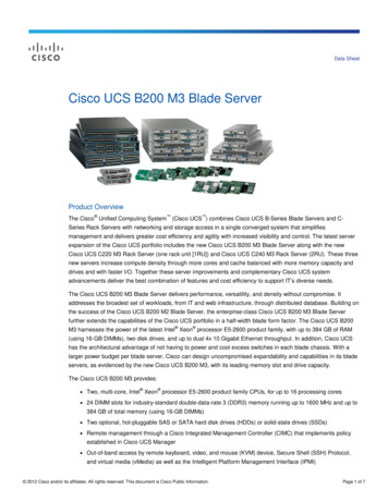
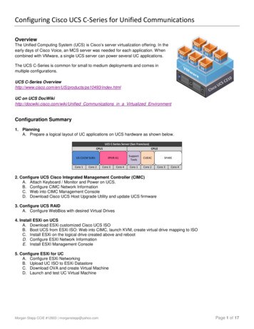
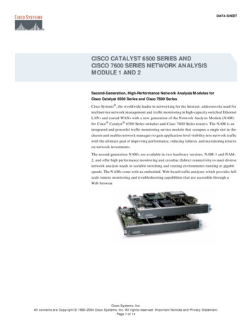
Chapter 1Windows Server 2003 InstallationInstallation on an Internal DriveStep 5Step 6Open a KVM console window for the target server (the blade server that contains the target drive):a.In the UCS Manager main window, click the Equipment tab in the Navigation pane.b.On the Equipment tab, expand Equipment Chassis Chassis Number Servers.c.Choose the server that you want to access through the KVM console.d.In the Work pane, click the General tab.e.In the Actions area, click KVM Console. The KVM console opens in a separate window.When the KVM console window launches, select Tools Launch Virtual Media.Cisco UCS B-Series Blade Servers Windows Installation Guide1-4OL-22764-01
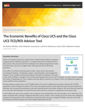
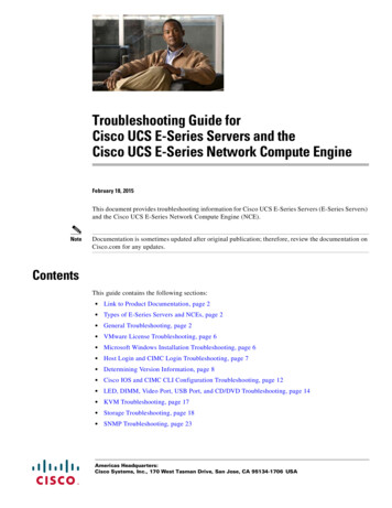
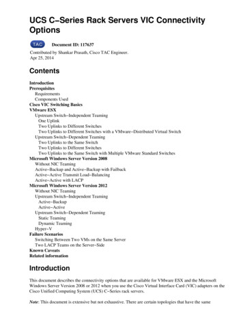
Chapter 1Windows Server 2003 InstallationInstallation on an Internal DriveStep 7In the Virtual Media Session window, provide the path to your Windows installation image:a.Click Add Image.b.Use the dialog box to navigate to your Windows Server 2003 ISO file and select it.The ISO image is displayed as a device in the Client View pane.TipStep 8Click Details to display the Details pane and observe the reading and writing progress.Provide the path to drivers for your mass storage controllers:a.Click Add Image.b.Navigate to the driver IMG image file for your device and operating system (where you saved it inStep 1) and select it.The IMG file appears in the Client View pane as a virtual floppy drive.c.Step 9When prompted whether you want to emulate the device as a floppy, click Yes.Check the check box in the Mapped column for each device that you want to mount, and then wait formapping to complete. Observe the progress in the Details pane.Cisco UCS B-Series Blade Servers Windows Installation GuideOL-22764-011-5
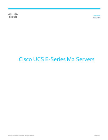
Chapter 1Windows Server 2003 InstallationInstallation on an Internal DriveStep 10When mapping is complete, power cycle the server so that the server reboots from the virtual CD/DVDand so the BIOS recognizes the media that you just added.NoteYou can power cycle the server by pressing the Power button on the server; by selecting Macros Ctrl-Alt-Del on the KVM Console window menu bar; or by clicking Reset in the UCS ManagerWork pane for the selected server.Step 11Watch the KVM console during bootup for the F2 prompt, and then press F2 to enter BIOS setup. Waitfor the setup utility screen to appear.NoteIf Quiet Boot is enabled (the default), you see the Cisco splash screen when the F2 prompt is displayed.NoteAfter you press F2 there is a small time interval before the BIOS setup utility is displayed because theserver continues to initialize devices and then displays the utility only after this is complete.Step 12On the BIOS setup utility screen, select the Boot Options tab and verify that the devices that you justadded in Step 7 and Step 8 are listed as bootable devices.Cisco UCS B-Series Blade Servers Windows Installation Guide1-6OL-22764-01
Chapter 1Windows Server 2003 InstallationInstallation on an Internal DriveStep 13Set the virtual floppy drive boot order:a.On the Boot Options screen, select Floppy Order.b.On the Floppy Order screen, set the new virtual floppy to be first in the list of floppy devices.c. Select Boot Option#1 and press Enter. Select Cisco Virtual Floppy in the pop-up window and press Enter.Press F10 to save your changes and exit the BIOS setup utility. The server power cycles.NoteWhen the server power cycles, it boots from the virtual CD/DVD that is mapped to your ISO installationimage. The server uses the boot order that is defined in its UCS Manager service profile (see Step 2).NoteDo not install the OS or drivers on any eUSB drive in your server. The Cisco UCS B440 Blade Servercan contain optional eUSB drives. If an eUSB drive is installed, the OS sees it as a local drive, listed as“Viking eUSB.” Cisco UCS Manager does not differentiate between the types of local drives. If an OSis installed on more than one local drive or on an internal USB drive (eUSB), you cannot specify whichof these local drives the server should use as the boot drive.Step 14NotePress Enter when prompted to boot from CD.In the next step, you must watch immediately for the prompt to press F6 and then press F6. During theinitial startup of the Windows installer, a message at the bottom of the window will say “Press F6 toinstall third-party drivers.”Cisco UCS B-Series Blade Servers Windows Installation GuideOL-22764-011-7
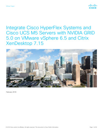
Chapter 1Windows Server 2003 InstallationInstallation on an Internal DriveStep 15Install the drivers for your mass storage device from the virtual floppy:a.After the Windows Setup screen appears, immediately watch for the prompt to press F6, and thenpress F6 to install third-party drivers for your mass storage device during the installation process.b.Continue to observe the Windows installation process and when prompted, press S to specifyadditional device.c.Select your mass storage device from the list and press Enter. The drivers for your mass storagedevice are installed from the virtual floppy.Cisco UCS B-Series Blade Servers Windows Installation Guide1-8OL-22764-01
Chapter 1Windows Server 2003 InstallationInstallation on an Internal DriveNoteDo not inst
† The Cisco UCS B-Series Drivers CD, or the ISO image of this CD from Cisco.com. † If installing to one of the LSI RAID controllers, configure a LUN to which you will install the OS. † The Windows installation ISO image (or CD/DVD)