Transcription
Installation & Instruction ManualAll Residential & Small System Models(except EZ95)RadonAway3 Saber Way Ward Hill, MA 01835radonaway.comIN063 Rev. B 0713
TABLE OF CONTENTS & FIGURES1. PRE-INSTALLATION. 31.1. Safety Matters.31.2. Water Flow Requirements.41.3. Unpacking and Locating System Components.51.3.1. Unpack All System Components. 51.3.2. Locate All Components.51.4. Use Qualified Technicians.51.5. Full Water Test.52. INSTALLATION INSTRUCTIONS.62.1. System Location.72.2. Readying the AIRaiderTM for Installation.72.3. Plumbing Hook-up.92.4. Electrical Hook-up.112.5. Vent Line Installation.162.6. Remote Air Intake.172.7. System Start-up. 182.8. System Check.193. RETESTING. 204. MAINTENANCE.204.1. Six Month Service (recommended).204.2. Annual Service (required).215. TROUBLE SHOOTING.22LIMITED WARRANTY.23APPENDICESA.1. Pump Specification, 433-S50 Systems, pump model 20DOMO5121 1.insertTable of FiguresFigure 1 a,b,c - Typical Systems (433-S, 433, 321).6Figure 2 - Pump & Bypass Assembly (433/321).7Figure 3 - Installed System (433, 321).8Figure 4 - Plumbing Installation (433-S50).9Figure 5 - Plumbing Installation (433-S50X).10Figure 6 - Wiring Diagram 433 115V/230V.12Figure 7 - Wiring Diagram 433 S50/115V.13Figure 8 - Wiring Diagram S50X/115V.14Figure 9 - Wiring Diagram 321/115V.15Figure 10 - Vent Line Connection.16Figure 11 - Vent Line Installation (2 inch).16Figure 12 - Vent Line Installation (3 inch).16Figure 13 - Air Filter.17Figure 14 - Air Intake Connection.17Figure 15 - Installed AIRaiderTM (433-S50).18IN063 Rev. B 0813Page 2 of 24
1PRE-INSTALLATION1. Pre-InstallationThe AIRaiderTM Systems are diffused bubble aeration systems for the removal of radon and otherVOC’s from residential and municipal water supplies. This installation/operation manual is designedto guide professionals through the safe and proper installation of the AIRaiderTM Systems.Before beginning the installation of the AIRaiderTM System, there are 5 items to be considered.They are:1. Safety2. Installation Site Requirements3. Inspection of System Components4. Necessity for Qualified Technicians5. Knowledge of all Contaminants in the Water1.1. Safety MattersSafety is the most important step in the installation process. Never perform any step of the installationthat you are not qualified to perform (i.e. Electrical or plumbing hook up). It is important that you readthrough the entire manual prior to beginning the installation. When performing the installation, workslowly and deliberately. Follow all instructions carefully and never take shortcuts. Our team oftechnicians is available to answer your questions at 800-355-0901.WORK SAFELY!IN063 Rev. B 0813Page 3 of 24
1PRE-INSTALLATION1.2. Water Flow RequirementsThe standard residential AIRaiderTM Systems are designed for use with water flows up to 20 gallonsper minute (GPM).* The system comes equipped with an outflow ball valve. If higher/ lower systemoutflow is needed, open/close the ball valve by the amount necessary to balance the system. The wellpump output must produce at least 1 GPM more than theoutput of the AIRaiderTM (i.e. well output 8 GPM ; AIRaiderTM outflow setting 7 GPM) for proper system performance. If the well pumpoutput is less than the system output the AIRaiderTM will run dry and possible damage may occur. Toprevent this from occuring the water flow rate must be determined before the system is installed.*Some AIRaiderTM Systems are not recommended for high flow residential properties. All repressurization systems(except for the AIRaiderTM EZ95,433-S50 & 433-S50X) are sold separately. Proper repressurization systemsizing is required to meet water flow needs. Consult manufacturer if assistance is needed for system selection.In order to determine available water flow rate the following is needed: Garden Hose Five-Gallon Bucket A Stop Watch or Watch with a Second HandOr A Water Flow MeterHousehold water use must be discontinued during the following flow rate test.Mid-Range Flow Rate Test:1. Attach garden hose to the drain connection on the base of the Well Pressure Tank.2. Open the drain valve and run water for 15 minutes.3. After 15 minutes, check the pressure gauge on the well system. Adjust the drain valve (open orclose) as needed to maintain the required running system pressure (constant pressure on gauge)with the well pump running continuously.4. Run for 5 minutes while ensuring that the pressure is not fluctuating.5. Run water from the hose into a five gallon bucket. Using a stop watch, time how many seconds ittakes to fill the bucket (Z sec.).6. Determine the GPM by dividing 60 seconds by the number of seconds it took to fill the bucket(Z sec.). Multiply the answer by 5 gallons. This gives you the GPM. GPM ( 60 / Z ) x 57. Repeat steps 5 and 6 and average the 2 numbers. The answer is the well pump output in gallonsper minute. It is recommended that this number be indelibly recorded in an obvious location,together with the date of test, as it will be required when setting the AIRaiderTM System and maybe required for future troubleshooting of the well pump system or the AIRaiderTM System.IN063 Rev. B 0813Page 4 of 24
PRE-INSTALLATION11.3. Unpacking and Locating System Components1.3.1. Unpack All System ComponentsRemove all packing material and discard appropriately away from the work area.1.3.2. Locate All ComponentsCheck to ensure all components are intact and included in shipment.(See Figure 5 and 8)Included component list (may vary with order): Tank Assembly with Solenoid Assembly Control Panel* and Float Switches Submersible Pump** Jet Pump and Bladder Tank Assembly*** Brass – Bypass Assembly, Pump Brass, and Tank Brass**** Installation Kit – Manual, Pressure Gauge, etc.* Model 321 does not come equipped with a control panel** Mounted internally on 433-S50 and 433-S75 Systems, not supplied with 433 and 321 Systems.*** Pump packages are sold separately on 321 and 433 Systems, and will vary with the order.Bladder Tanks are sold separately.**** Sold separately on 321 and 433 Systems. Standard systems are equipped for a ¾”plumbing connection. 1” plumbing connection is available on 433 Systems only (Not 433433-S50 or 433-S75). Please specify plumbing connection requirements when ordering.Bypass Assembly is integral on 433-S50 Systems Only.1.4. Use Qualified TechniciansA Licensed Plumber, Electrician, Contractor and/or Certified Water Treatment Specialist may berequired to install the AIRaiderTM System in accordance with the installation instructions. All wiringmust be performed in accordance with the National Fire Protection Association’s (NFPA)”NationalElectrical Code, Standard #70”-current edition for all commercial and industrial work. All wiringmust be performed by a qualified and licensed electrician. Check your Local and State Code andLicensing requirements. Failure to follow the instructions may lead to poor system performance and/or possible system damage.The Installation must comply with all applicable Local and State Codes andNFPA National Electrical Code, Standard #70!1.5. Full Water TestA full Water Sample Analysis must be performed to determine the quality of the water that requirestreatment. In many water supplies, contaminants other than radon are present and may need to bepre-treated in order for the AIRaiderTM to work properly. The AIRaiderTM System is only effective forthe removal of radon and some other VOC’s. The Aeration Process employed by the AIRaiderTMSystem and other radon removal systems can worsen problems due to iron or manganese contaminantsin the water supply. For optimal removal of radon or other VOC’s, other contaminants such as iron, ormanganese must be removed before the water supply enters the AIRaiderTM System.Failure to remove other contaminants can reduce the effectiveness of thesystem and may result in system damage!IN063 Rev. B 0813Page 5 of 24
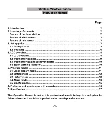
1INSTALLATION INSTRUCTIONS22. Installation InstructionsOVERVIEWNow you are ready to begin the installation process. The eight steps to properly install the AIRaiderTMSystem are listed below. Read all components of each step prior to beginning the actual installation.1. System Location2. Readying the System for Installation3. Plumbing Hook-up4. Electrical Hook-up5. Vent Line Installation6. Remote Air Intake Installation7. System Start-up8. System CheckSAFETY TIP: Do Not undertake any step for whichyou are Not Qualified.433-S50433 & 433-1321Figure 1 a,b,cTypical System(Repressurization Systems not shown, sold separately on 321, 433 and 433-1)IN063 Rev. B 0813Page 6 of 24
12INSTALLATION INSTRUCTIONS2.1. System LocationWhen selecting the location for the AIRaiderTM System, five factors should be among those considered:1. System Plumbing Hook-up. Find a location that will minimize the amount of plumbingnecessary, this is typically in proximity to the well tank.2. Electrical Hook-up. Keep in mind the need for accessibility to a 20 Amp dedicated 120VACpower supply or 30 Amp dedicated 230VAC for 230V 433 Systems.3. Exhaust Line Venting. The location of the system must allow for outside venting of thesystem exhaust above the eave of the structure. The manufacturer requires that the exhaustpipe pitch back toward the system (see Section 2.6).4. Remote Air Intake. If the system must be installed in an area with questionable air quality(i.e. furnace room, garage, crawl space) then ducting from the air intake to a remote locationhaving good air quality may be required.5. System Must Be Level. The system should not be located on a significant slope as this mayimpede system performance.Place the system in the location acceptable to customer that maximizes the ease of installation.All Local and State codes as well as any applicable AARST, EPA and/or State Radon standards mustbe adhered to when locating the AIRaiderTM (i.e. away from electrical panel, furnace, exits, etc.).2.2. Readying the AIRaiderTM for InstallationFor 433 and 321 systems (433 Illustrated). This section does not apply to Systems with integral pumps (433-S50 & 433-S50X Systems).1. If using the Grundfos MQ3-45 Pump attach Mounting Bracket to wall as shown in Fig. 3 (page 8). Notebracket hole height is specific to the Grundfos MQ345. If using a different pump adjust bracket height asrequired to place pump suction pipe centerline at thesystem outlet centerline as specified in Fig. 3.Note: Short horizontal pipe run from system outlet to pump inlet is optimal. If thispump location is impractical because of space constraints the pump may be locatedremotely at a higher location, but pump lift, pipe diameter, and equivalent pipe lengthmust comply with limits specified in the pump installation instructions.Do not mount pump lower than shown as removal of the pump forservice may result in tank contents siphoning out onto the floor!2. Install the Suction Check Valve provided with theGrundfos MQ3 Pump into the pump inlet as shown inthe pump installation instructions. This will preventloss of pump prime and possible interruptions in thewater supply to the house. Remove the priming plugfrom the pump and add the specified volume (SeePump Installation Instructions) of water to the pump.Either re-install the priming plug or install a ⅜” NPTx 2” long pipe nipple and attach a ¼” NPT Pressure Gaugewith with ¼” x ⅜” FNPT Reducer to the pipe nipple (Fig. 2).IN063 Rev. B 0813Figure 2Pump & Bypass AssemblyPage 7 of 24
12INSTALLATION INSTRUCTIONS3. Sit the pump onto the mounting bracket and connect pump inlet to system outlet. The system outletis provided with a ¾” Sharkbite Connection suitable for ¾” Nominal Copper Tube or Pex Tube;insertion length into Sharkbite Fitting is 1”. Additional fittings will be required to connect the tube tothe 1” MNPT threaded connection on the MQ3-45 Pump. Fittings required may vary with pump used.Cut the tubing to the length required to align the pump base with the mounting holes in the pumpmounting bracket. Bolt the pump to the mounting bracket.4. With the System located as desired, install the pipe/tube from the pump discharge to the desiredlocation of supply to house. At the house end a tee is required to accommodate supply to house and toSystem Bypass Connection. Fittings will be required to connect to the 1” MNPT threaded connection onthe MQ3-45 Pump. Fittings required may vary with pump used. The optional Bladder Tank has a ¾”MNPT threaded connection. A tee will be required if the bladder tank is installed, otherwise an elbowmay be used at the same location. To facilitate removal of pump for service, a quick disconnect(sharkbite as illustrated, or pipe union) is recommended on the pump side of the required SystemOutlet Valve (normally open ball valve).Figure 3Installed 433 ND System5. Install pipe/tube from System inlet (Fig. 2) to the desired location of the supply from the well tank.At the supply end a tee is required to accommodate supply from the well and the system bypassconnection. The system inlet is provided with a ¾” Sharkbite Elbow suitable for ¾” Nominal CopperTube or Pex Tube, insertion length into Sharkbite Fitting is 1”. A System Inlet Valve (normally openball valve) is required between the tee and Sharkbite Elbow.6. Install the pipe/tube between the tees at the desired locations of the supply to house and the supplyfrom well. A System Bypass Valve (Normally Closed Ball Valve) is required between the tees.IN063 Rev. B 0813Page 8 of 24
12INSTALLATION INSTRUCTIONS2.3. Plumbing Hook-upAll Plumbing should be performed in accordance with Local and State Codes by aQualified Plumber.1. Shut off the water main valvelocated after the pressure tank.2. Drain the water line.3. Plumb the system into the water lineafter the pressure tank and all otherwater treatment equipment.4. Plumb the water line from theexisting pressure tank into the Inlet Tee.5. Plumb the water line to the houseinto the Outlet Tee (Fig. 2, 4 or 5depending on System and Pump).A flow restrictor or gate valve in thewater line to the house is required forbalancing the system flow. A BladderTank , minimum capacity 5 gallons isrequired for 433-S50 Systems (20gal.min. for 433-S50X).WARNING: Bladder Tank must besupported by hanger attached to wallor joist.6. Making sure the Bypass valve is openand Inlet and Outlet Valves are closed,slowly open the water main valve andcheck for leaks.Figure 4Plumbing Installation 433S ND System7. Slowly change bypass to the “service” configuration, Bypass valve closed, inlet and outlet valvesopen. Prime jet pump as per Manufacturers Instructions (See enclosed Jet Pump Manual) if notpreviously primed. Note that integral pump on 433-S7
The AIRaiderTM Systems are diffused bubble aeration systems for the removal of radon and other VOC’s from residential and municipal water supplies. This installation/operation manual is designed to guide professionals through th