Transcription
Wireless Weather StationInstruction ManualPage1. Introduction.22. Inventory of contents.2Feature of the base station.2Feature of wind sensor.2Feature of rain sensor.33. Set up guide.33.1 Battery install.33.2 Mounting.64. LCD overview.84.1 LCD overview.84.2 Weather forecasting.94.3 Weather forecast tendency indicator.104.4 Storm warning indicator.105. Program modes.115.1 Quick display mode.115.2 Setting mode.125.3 History mode.125.4 Alarm mode.135.5 Min/Max mode.156. Problems and interference with operation.167. Specification .17This Operation Manual is part of this product and should be kept in a safe place forfuture reference. It contains important notes on setup and operation.- -
1. IntroductionThank you for purchasing this Professional Weather Center Designed for everyday use,the weather station will prove to be an asset of great value for your personal use in thehome or office. Please read this instruction manual thoroughly to fully understand thecorrect operation of your weather station and benefit from its unique features.2. Inventory of contents1) Base station2) WH1 sensor including thermo-hygro sensor, rain sensor, wind sensor3) Instruction manual4)2 adjustable hoops (to fix the mast to your desired location)The received data is continuously updated to bring you the latest weather information onthe base station’s LCD. The outdoor thermo-hygro sensors is the main data communicationunit since both the wind and rain sensors are connected to the thermo-hygro sensor foroperating power and rely on it to communicate to the base station. Weather data sent fromthe thermo-hygro sensor is transmitted through wireless link.Additional equipment (not included)1. 3 Fresh AA 1.5V LR6 Alkaline batteries.2. 2 Fresh AA 1.5V LR6 Alkaline batteries.Feature of the base station: Indoor and outdoor temperature display in degrees Fahrenheit or Celsius (userselectable) Indoor and outdoor relative humidity displays Barometric pressure reading in inHg or hPa, absolute or relative (user selectable) Detailed display of rainfall data in 1 hour, 24 hours, one week, one month and total sincelast reset. (user selectable in mm or inch) Wind speed in mph, km/h, m/s, knots or Beaufort (user selectable) Wind chill temperature display Dew point temperature display- -
Weather forecast display by weather icons (sunny, cloudy, rainy) Weather forecast tendency arrow Storm warning alarm Display of extensive weather data, in all cases with programmable alarm functions forcertain weather conditions as well as records of all minimum and maximum values alongwith time and date of their recordings Supper bright green LED back light DCF Radio controlled time and date with manual setting option 12 or 24 hour time display Perpetual calendar Time zone setting Automatic daylight saving time function based on Germany DST system ( for those usersusing the clock outside the time zone of Germany, the DST automatic change time willbe delayed or triggered earlier according to the time zone difference accordingly) Wall hanging or free standing Synchronized instant reception for outdoor weather data as well as radio controlled timesignalFeatures of wind sensorThe wind sensor measures wind speed and sends the data to thermo-hygro sensor, whichin turn transmits the data to the base station.Feature of rain sensorThe rain sensor measures the rainfall and sends the data to thermo-hygro sensor, whichin turn transmits the data to the base station. Operating power is taken from the thermohygro sensor by a cable connection3. Set up Guide3.1 Battery install- -
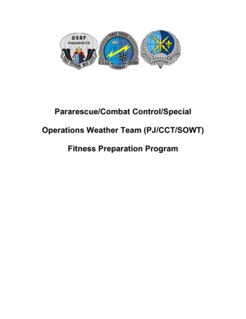
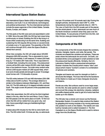
Setting up using batteriesThermo-hygro SensorLED IndicatorSensor SocketsBattery coverBatteryCompartmentNote: To avoid operating problems, please take note of battery polarity before/wheninserting any Alkaline Batteries. Use good quality Alkaline Batteries and avoidrechargeable batteries. Since the radio controlled time receiver is built inside thesensor, please do not put the sensor close to area with mass metal or obviousshielding objects around.1)Pull away the shower proof casing of the thermo-hygro sensor to reveal the two sockets(for the wind sensor and rain sensor)2)Connect the attached cables of wind and rain sensors to the corresponding socketsof the thermo-hygro sensor by clicking them into place. Make sure that rain and windsockets not swapped when plugging the phone jacket.3)Open the base station’s battery cover located at the back of the unit and insert 3 x AA,1.5V Alkaline batteries into the battery compartment and close the battery cover4)Open the battery cover of the thermo-hygro sensor located below the two sockets andinsert 2 x AA, 1.5V Alkaline batteries and close the coverEvery time the thermo-hygro sensor is powered up (for example after a change ofbatteries), the LED indicator will light up for 4 seconds (if no LED light up or is lightedpermanently, make sure the battery is inserted the correct way or a proper reset ishappened). After the thermo-hygro sensor is powered up, the sensor will transmit weather- -
data for 24s, and then the sensor will start radio controlled time reception. During the RCCtime reception period (maximum 5 minutes), no weather data will be transmitted. The LEDindicator will be blinking 5 times once RCC signal was synchronized and the LED indicatorwill not light during any future regular RCC reception routines. Regular RF link will beestablished once RCC reception routine is finished.When the base station is powered up, a short beep will sound and all LCD segmentswill light up for about 3 seconds before it enters into learning mode to learn the sensorssecurity code.Note: DO NOT PRESS ANY KEY during the first 10 minutes learning period or beforeradio controlled time is displayed on the receiver. After both outdoor weather data andradio controlled time are displayed you can place your remote sensor outdoors and setyour time (if no RCC reception is possible). If there is no temperature reading in the indoorstation, make sure the units are within range of each other or repeat the battery installationprocedure. If a key is pressed before the weather station receives the temperature signal,you will need to follow the battery installation procedure again. Please wait minimum10seconds before re-insert the battery again to make a proper reset for bothtransmitter and receiver.Note : If a battery change on the transmitter side happened, the base station will beresynchronized to the transmitter again within the next 3 hours. If you want to shorten thereceiving data time, the base station has to re-install the battery so that it can have thenew security code learnt right way, but the previous weather data and alarm value settingsin base station will be lost.Note for Radio Controlled Time DCF:The time and date display is based on the signal provided by the highly accurategovernment operated atomic clock. The outdoor sensor will continue to scan for theradio controlled time signal each day despite it being manually set. If reception has beenunsuccessful, then the radio controlled time icon will not appear but reception will still beattempted continually. If reception has been successful, the received time and date willoverwrite the manually set time and date.- -
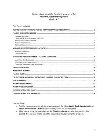
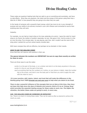
Note:When batteries require replacement for the base station, the low battery indicatorwill light up on the LCD.Please participate in the preservation of the environment by properlydisposing of all used-up batteries and accumulators at designated disposalpoints. Never dispose of batteries in a fire as this may cause explosion, riskof fire or leakage of dangerous chemicals and fumes3.2 Mounting1) Base stationWith one foldable leg at the back of the unit, the base station can be placed onto any flatsurface or wall mounted at the desired location by the hanging holes also at the back of theunit. It is important to check that outdoor sensor data can be received before permanentlymounting any of the units2) Remote sensorFor accurate results, the remote sensor mast should be securely mounted onto ahorizontal surface and in an open area away from trees or other coverings where rainfall orwind speed may be reduced causing inaccurate readinga). mounting the wind sensor onto a masterFirstly, check that the wind-fan can rotate freely before fixing the unit. The wind sensorshould now be mounted using the screw onto a mast provided to allow the wind to travelaround the sensor unhindered from all directions.FrontBack-6-
b.) Mounting the rain sensorc.)Mounting the thermo-hygro sensor same as rain sensord.) Fix the whole set to a pole with the two adjustable hoops.-7-
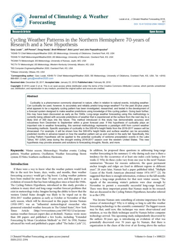
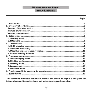
Once the wind sensor and rain sensor are fixed onto the mast, connect the cable to thecorresponding thermo-hygro sensor socket.4. LCD overview4. LCD overviewThe following illustration shows the full segments of the LCD for description purposes onlyand will not appear like this during normal operation and use.1 9330 4567891011141 1315161719 0 1 3 618 4 7 5 8-8-
1. Time2. Alarm on indicator3. Day of week/ time zone / history4. Date5. Indoor temperature display6. Indoor humidity display7. Indoor temperature and humidity lowalarm and high alarm8. Temperature display unit9. General indoor alarm icon10. MIN/MAX information11. Wind chill and dew pointtemperature display12. Outdoor temperature and humiditydisplay13. Outdoor temperature and humiditylow alarm and high alarm14. Temperature display unit15. General outdoor alarm icon16. Weather forecast icon17. Weather tendency indicator18. Pressure unit (relative or absolute)19. Pressure with 24 hour history graph20. Pressure low alarm and high alarm21. Pressure display unit (inHg or hPa)22. Pressure alarm on indicator23. Wind speed display unit (m/s, km/h,knots, chill mph, bft)24. Wind speed high alarm25. Wind alarm on indicator26. Rainfall display unit (mm/in)27. Rainfall 1h, 24h, week, month or totalhour display28. Rainfall alarm on indicator29. Radio controlled time version DCF30. Radio controlled time icon4.2 Weather forecastingSunnyPartly CloudyCloudyRainyThe four weather icons Sunny, partly Cloudy, Cloudy and Rainy represent the weatherforecasting. For every sudden or significant change in air pressure, the weather icons willupdate accordingly to represent the change in weather.-9-
4.3 Weather forecast tendency indicatorThe weather tendency indicators arrow is located between the weather icons to showthe air pressure tendency and provide a forecast of the weather to be expected by thedecreasing or increasing air pressure. The rightward arrow means that the air pressure isincreasing and the weather is expected to become better. The leftward arrow means thatthe air pressure is decreasing and the weather is expected to become worse.The change of weather forecast icon is in accord to the relationship between currentrelative pressure and the pressure change since last twelve hours. If the weather ischanging, weather tendency indicator (animated arrows) will be flashing. And after the nextthree hours if weather conditions have become stable, the arrows will fix indicating a stablecondition happened.Examples of changing weather icons:4.4 Storm warning indicatorThe storm threshold can be set to suit the user’s requirement for storm forecasting from3-9hPa (default 4hPa). When there is a fall over pressure threshold within 3 hours, thestorm forecasting will be activated, the clouds with rain icon and tendency arrows will flashfor 3 hours indicating the storm warning feature has been activated.- 0-
Notes to pressure sensitivity setting for weather forecasting:The pressure threshold can be set to suit the user’s requirement for weather forecastingfrom 2-4hPa (default 2hPa). For areas that experience frequent changes in air pressurerequires a higher setting compared to an area where the air pressure is stagnant. Forexam
Wind speed in mph, km/h, m/s, knots or Beaufort (user selectable) Wind chill temperature display Dew point temperature display