Transcription
G Intrusion PreventionApplianceQuick Start Guide
Internet Security Systems, Inc.6303 Barfield RoadAtlanta, Georgia 30328-4233United States(404) 236-2600http://www.iss.net Internet Security Systems, Inc. 2003-2005. All rights reserved worldwide. Customers may make reasonable numbers ofcopies of this publication for internal use only. This publication may not otherwise be copied or reproduced, in whole or inpart, by any other person or entity without the express prior written consent of Internet Security Systems, Inc.Patent pending.Internet Security Systems, ADDME, ActiveAlert, AlertCon, the AlertCon logos, FireCell, FlexCheck, SecurityFusion,SecurePartner, SiteProtector, SecureU, System Scanner, Virtual Patch, Wireless Scanner, and X-Press Update are trademarksand service marks; Database Scanner, Internet Scanner, the Internet Security Systems logo, Online Scanner, Proventia,RealSecure, SAFEsuite, Secure Steps, and X-Force are registered trademarks and service marks of Internet SecuritySystems, Inc. Network ICE, the Network ICE logo, and ICEpac are trademarks, BlackICE a licensed trademark, and ICEcapa registered trademark of Network ICE Corporation, a wholly owned subsidiary of Internet Security Systems, Inc.Powering Content Security is a trademark and Cobion is a registered trademark of Cobion AG, a wholly owned subsidiaryof Internet Security Systems, Inc. SilentRunner is a registered trademark of Raytheon Company. Acrobat and Adobe areregistered trademarks of Adobe Systems Incorporated. Certicom is a trademark and Security Builder is a registeredtrademark of Certicom Corp. Check Point, FireWall-1, OPSEC, Provider-1, and VPN-1 are registered trademarks of CheckPoint Software Technologies Ltd. or its affiliates. Cisco and Cisco IOS are registered trademarks of Cisco Systems, Inc. HPUX and OpenView are registered trademarks of Hewlett-Packard Company. IBM and AIX are registered trademarks ofIBM Corporation. InstallShield is a registered trademark and service mark of InstallShield Software Corporation in theUnited States and/or other countries. Intel and Pentium are registered trademarks of Intel. Lucent is a trademark of LucentTechnologies, Inc. ActiveX, Microsoft, Windows, and Windows NT are either registered trademarks or trademarks ofMicrosoft Corporation. Net8, Oracle, Oracle8, SQL*Loader, and SQL*Plus are trademarks or registered trademarks ofOracle Corporation. Seagate Crystal Reports, Seagate Info, Seagate, Seagate Software, and the Seagate logo are trademarksor registered trademarks of Seagate Software Holdings, Inc. and/or Seagate Technology, Inc. Secure Shell and SSH aretrademarks or registered trademarks of SSH Communications Security. iplanet, Sun, Sun Microsystems, the Sun Logo,Netra, SHIELD, Solaris, SPARC, and UltraSPARC are trademarks or registered trademarks of Sun Microsystems, Inc. in theUnited States and other countries. All SPARC trademarks are used under license and are trademarks or registeredtrademarks of SPARC International, Inc. in the United States and other countries. Adaptive Server, SQL, SQL Server, andSybase are trademarks of Sybase, Inc., its affiliates and licensers. Tivoli is a registered trademark of Tivoli Systems Inc.UNIX is a registered trademark in the United States and other countries, licensed exclusively through X/Open Company,Ltd. All other trademarks are the property of their respective owners and are used here in an editorial context withoutintent of infringement. Specifications are subject to change without notice. Intel Corporation, 2002.Disclaimer: The information contained in this document may change without notice, and may have been altered orchanged if you have received it from a source other than ISS or the X-Force. Use of this information constitutes acceptancefor use in an “AS IS” condition, without warranties of any kind, and any use of this information is at the user’s own risk.ISS and the X-Force disclaim all warranties, either expressed or implied, including the warranties of merchantability andfitness for a particular purpose. In no event shall ISS or the X-Force be liable for any damages whatsoever, including direct,indirect, incidental, consequential or special damages, arising from the use or dissemination hereof, even if ISS or theX-Force has been advised of the possibility of such damages. Some states do not allow the exclusion or limitation ofliability for consequential or incidental damages, so the foregoing limitation may not apply.Reference herein to any specific commercial products, process, or service by trade name, trademark, manufacturer, orotherwise, does not necessarily constitute or imply its endorsement, recommendation, or favoring by Internet SecuritySystems, Inc. The views and opinions of authors expressed herein do not necessarily state or reflect those of InternetSecurity Systems, Inc., and shall not be used for advertising or product endorsement purposes.Links and addresses to Internet resources are inspected thoroughly prior to release, but the ever-changing nature of theInternet prevents Internet Security Systems from guaranteeing the content or existence of the resource. When possible, thereference contains alternate sites or keywords that could be used to acquire the information by other methods. If you find abroken or inappropriate link, please send an email with the topic name, link, and its behavior to support@iss.net.Document part number: DOC-QSG-PROVIPAG-006-CFebruary 24, 2006
ContentsPreface . . . . . . . . . . . . . . . . . . . . . . . . . . . . . . . . . . . . . . . . . . . . . . . . . . . . . . .5Overview . . . . . . . . . . . . . . . . . . . . . . . . . . . . . . . . . . . . . . . . . . . . . . . . . . . . . . 5Getting Started . . . . . . . . . . . . . . . . . . . . . . . . . . . . . . . . . . . . . . . . . . . . . . . . . . 9Chapter 1: Connecting the ApplianceOverview . . . . . . . . . . . . . . . . . . . . . . . . . . . . . . . . . . . . .The G100/G200/G1000 and G1200 Front and Back Panels .The G400 and G2000 Front and Back Panels . . . . . . . . . . . .Standard Inline Deployment Scenarios . . . . . . . . . . . . . . . . .Connecting the Cables and Starting the Appliance . . . . . . . . .Configuring the Appliance External Bypass Unit . . . . . . . . . . .111220273032.37384045485153Index . . . . . . . . . . . . . . . . . . . . . . . . . . . . . . . . . . . . . . . . . . . . . . . . . . . . . . . .57Chapter 2: Configuring the ApplianceOverview . . . . . . . . . . . . . . .Configuration Checklist . . . . . .Logging On and Configuring theAccessing Proventia Manager .Managing the Appliance . . . . .Reinstalling the Appliance . . . .Getting Technical Support . . . .Appliance .Proventia G Intrusion Prevention Appliance Quick Start Guide.3
Contents4
PrefaceOverviewIntroductionThis guide is designed to help you connect and configure your ProventiaG Intrusion Prevention Appliance.ScopeThis guide describes the appliance models (G100, G200, G1000 andG1200, G400, G400 (Rev A) and G2000) and explains the different ways toconnect the appliances to your network. It also includes initial appliancesetup procedures.Important: To upgrade legacy G100, G200, G1000 and G1200 modelappliances to firmware version 1.2, see Proventia G Next GenerationInstallation and Upgrade Procedures. To configure and manage appliancesrunning firmware version 1.2, see the Proventia G Intrusion PreventionAppliances User Guide.Additional documentation is located on the ISS Web site at his guide is intended for network security system administratorsresponsible for installing and configuring Proventia G IntrusionPrevention Appliances. A fundamental knowledge of network securitypolicies and IP network configuration is helpful.Proventia G Intrusion Prevention Appliance Quick Start Guide5
PrefaceWhat’s new in thisreleaseThe new features in this release include the following: G100, G200, G1000, and G1200 appliance management throughProventia Manager. Manage appliance settings using the Web-basedProventia Manager interface. Ignore response available for Security Events and Response Filters.Manually set the Ignore response to tell the appliance to ignoreevents that are not a threat to your network, reducing the number ofevents you need to track. Enhanced diagnostics and statistics. Using the Driver, PacketAnalysis, and Protection statistics, view network traffic the appliancehas processed to troubleshoot or to determine important trends.Other changes in this release include: for G400 and G2000 models, the ability to configure high availability(HA) through Proventia Manager card management is now called adapter management SNMP read access configuration ability to configure kill port link settingsImportant: You must update SiteProtector to the 5.18 Database ServicePack prior to installing the Proventia G firmware version 1.2. See theReadme for more information.Verifying packagecontents6The Proventia G appliance packaging includes the following: appliance power cord appliance recovery CD null modem serial cable warranty statement bezel cover with keys mouse/keyboard Y-cable crossover connectors and patch cables (copper only) rack mount kits and instructions
OverviewRack mount kitmaterialsTable 1 describes the materials included in the rack mount kit for yourappliance. Rack mount kit instructions are included in your appliancebox and are also available online at http://www.iss.net/support/documentation.This model kit.Includes.G400C, G400F, and G400CFslide rail kit (option 1)mid-mount rack kit (option 2)G2000C, G2000F, and G2000CFtool-less slide rail kitTable 1: G Appliance rack mount kitsExternal fiberbypass unitThe full fiber and copper-fiber hybrid model appliances—G400F, G400CF,G2000F, and G2000CF—use an external bypass unit. If you must use theProventia External Fiber Bypass Unit with your appliance, see“Configuring the Appliance External Bypass Unit” on page 32 fordetailed information.Proventia G Intrusion Prevention Appliance Quick Start Guide7
PrefaceRelated publications For the latest available appliance documentation, refer to the Help andthe Readme files associated with each appliance release. Additionaldocuments are available on the ISS Web site at the following Additional documentation includes the following:DocumentSupportsProventia G Intrusion PreventionAppliances User GuideAll Proventia G appliances running releaseversion 1.2 or laterProventia G Next GenerationInstallation and UpgradeProcedures GuideG100/G200/G1000/G1200 appliancesrunning software versions prior to version 1.2that need to be upgradedProventia G100/G200/G1000/G1200 Appliance Quick StartGuideExisting G100/G200/G1000/G1200 modelappliances running software versions prior toversion 1.2SiteProtector Documentation:Any appliance managed throughSiteProtector SiteProtector InstallationGuide SiteProtector User Guide forSecurity Managers SiteProtector TechnicalReference Guide SiteProtector Best PracticesGuideTable 2: Additional documentation8
Getting StartedGetting StartedSetup processoverviewThe Proventia G setup is a 10-step setup process, as follows:StepDescriptionWhere to find theprocedure1Connect the appliance cables to acomputer and turn on the appliance.“Connecting the Cables andStarting the Appliance” onpage 30.2Start a terminal emulation session.“Setting up terminalemulation” on page 31.3Gather required information.“Configuration Checklist” onpage 38.4Log in to the Proventia Setup Assistantas admin/admin.“Logging on and startingProventia setup” on page 40.5Perform configuration steps.“Configuring the networkinterface and host” onpage 41.6Contact your Sales Representative foryour license registration number.“Installing licenses andupdates” on page 47.Do the following:1. Register your customer license atthe ISS License Registration center(https://www1.iss.net/cgibin/lrc).2. Download the license key file fromthe ISS Registration Center to yourcomputer.Note: ISS recommends that youupload the license key file to adesignated directory so that theappliance can download and installthe latest updates automatically.3. Upload the license when you log into Proventia Manager, whenprompted.Table 3: Setup processProventia G Intrusion Prevention Appliance Quick Start Guide9
PrefaceStep7DescriptionVerify you have the following: “Accessing ProventiaInternet Explorer version 6.0 or later Manager” on page 45.Java Runtime Environment (JRE)version 1.4.2. The applicationprompts you with an installation linkif you do not have it installed.8Open Internet Explorer and log in toProventia Manager as usernameadmin and the password youconfigured during Proventia Setup.“Logging on to ProventiaManager” on page 45.9Install license.10Apply updates.“Installing licenses andupdates” on page 47Table 3: Setup process (Continued)10Where to find theprocedure
Chapter 1Connecting the ApplianceOverviewIntroductionThis chapter contains diagrams and connection procedures all appliances,as well as standard inline deployment scenarios and information onconnecting the external fiber bypass unit.In this chapterThis chapter contains the following topics:TopicPageThe G100/G200/G1000 and G1200 Front and Back Panels12The G400 and G2000 Front and Back Panels20Standard Inline Deployment Scenarios27Connecting the Cables and Starting the Appliance30Configuring the Appliance External Bypass Unit32Proventia G Intrusion Prevention Appliance Quick Start Guide11
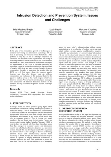
Chapter 1: Connecting the ApplianceThe G100/G200/G1000 and G1200 Front and BackPanelsIntroductionThis topic identifies the front and back panels of a Proventia G100, G200,G1000, and G1200 appliance, along with descriptions for each item.Front panel diagramand legendThe Proventia G100, G200, G1000, G1200 front panel is shown in Figure 1:A BC DE FGHILKJFigure 1: G100/G200/G1000/G1200 appliance front panelThe front panel of a Proventia G100, G200, G1000, G1200 applianceincludes the following:12 A - RSKill Interface (2) LED B - Management Interface (1) LED C - Power Button D - Power LED E - Hard Drive Activity LED F - Fault LED G - System ID LED H - System ID Button I - Reset Button J - USB (unused) K - Unused L - Video
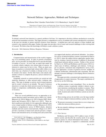
The G100/G200/G1000 and G1200 Front and Back PanelsCaution: You must operate this unit with the top cover installed to ensureproper cooling.Back panel diagram(G100/G200)PortAUSBPortThe Proventia G100 /G200 (1U) back panel is shown in Figure 2:PortBRSKillInterface (2)ManagementInterface efReleaseLeverFigure 2: G100/G200 appliance back panelProventia G Intrusion Prevention Appliance Quick Start Guide13
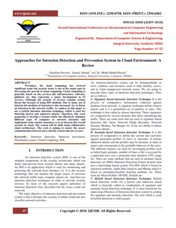
Chapter 1: Connecting the ApplianceBack panel diagram(G1000/G1200)The network card is on the right side of the Proventia G1000 appliance.The Proventia G1200 appliance has eight ports. The Proventia G1200offers AC or a DC power option. The Proventia G1000/G1200 (2U) backpanel is shown in Figure 3.Note: The AC power option is shown in Figure 3. The DC powerinformation is shown in Figure 4 on page , BC, DReleaseLever 1cE, FG, HKillInterface (2)This socket powers this moduleACPowerUSBPortManagementInterface (1)VideoSerialPortUSBPortKeyboardSCSIFigure 3: G1000/G1200 appliance back panel14
The G100/G200/G1000 and G1200 Front and Back PanelsConnecting the ACpower cordThe Proventia G100/G200 (1U) appliances come with one AC powerconnector. The Proventia G1000/G1200 (2U) appliances come with dualstandard AC power connectors and a DC power option (G1200 only).To connect the AC power cord(s):1. Press the strain relief into the platform hole until it snaps into place.2. Place the power cord into the loop. Leave some slack in the powercord between the strain relief and the power supply.3. Pull the tab to secure the power cord in the loop.4. Insert the female end the power cord into the back of the appliance asshown in Figure 2 and Figure 3.5. Insert the male end of the power cord into a standard AC powersupply.DC power supplyThe DC power supply used with the Proventia G1200 appliance uses a -48to -60 VDC input switching power subsystem, which provides up to 470Watts with -48 to -60 VDC input and with current and remote senseregulation. The power subsystem consists of one or two 470-Watt powersupply modules. A system with two modules forms a redundant, hotswappable (1 1) power subsystem.Note: The DC power supply is only available for the Proventia G1200appliance.Proventia G Intrusion Prevention Appliance Quick Start Guide15
Chapter 1: Connecting the ApplianceBack panel diagram(G1200)The Proventia G1200 appliance has eight ports. DC power option is onlyoffered on the Proventia G1200 appliance. The Proventia G1200 (2U) backpanel is shown in Figure 4:Figure 4: G1200 appliance back panel with DC power optionDC power supplyfeatures16The DC power supply includes the following features: 470-Watt output capability in full DC input voltage range power good indication LEDs predictive failure warning internal cooling fans with multi-speed capability remote sense of 3.3-Volt, 5-Volt, and 12-Volt DC outputs “DC OK” circuitry for brown-out protection and recovery built-in load sharing capability
The G100/G200/G1000 and G1200 Front and Back PanelsInterfacerequirements forDC power built-in overloading protection capability onboard field replaceable unit (FRU) information I2C interface for server management functions integral handle for insertion/extractionTable 4 identifies the interface requirements for DC power:InterfaceDescriptionDC InputThe DC power source may produce hazardous voltage levelsexceeding -60 VDC and high energy levels above 240VA thatmay cause electric shock or burns. All DC input connectionsshould be made only by a qualified service person to preventinjury. All wiring terminals connected to the DC input terminalblock must be fully insulated with no exposed bare metal.DC OutputConnectorsThe power subsystem DC power and control signals areconnected to the server system by wire harnesses when thepower supply modules are inserted into the power subsystemenclosure. The safety ground pin of the power supply module isthe first pin to connect and the last to disconnect when themodule is being inserted or removed from the power subsystemhousing. In addition to the 5-V Standby, -12 V, 3.3 V, 5 V and 12 VDC outputs, the following signals and output pins areincluded: 3.3 VDC remote sense 5 VDC remote sense 12 VDC remote sense Remote sense return Power Subsystem On (DC PWR enable) Power GoodTable 4: Interface requirements for DC powerProventia G Intrusion Prevention Appliance Quick Start Guide17
Chapter 1: Connecting the ApplianceDC power supplymodule LEDindicatorsA single bi-color LED on the back of the system indicates the powersupply status. Table 5 lists the conditions the LED can indicate:Power Supply ConditionPower Supply LEDNo DC power to all PSUsOFFNo DC power to this PSU onlyAMBERDC present/Only Standby Outputs OnBLINK GREENPower supply DC outputs ON and OKGREENCurrent limitAMBERPower supply failure (OTP, OCP, OVP, UV)AMBERTable 5: DC power supply LED status conditionsNote: S Failure, PS Presence, PS Predictive Fail, 12 V Mon, 5 V Mon, and the 5V Standby rails failure are being monitored via an I2C interface chip.DC input voltagespecificationThe power supply will operate within all specified limits over the inputvoltage range outlined in Table 6. The power supply will power-off if theDC input is less than -34 oleranceMaximumInput CurrentVoltage-38VDC-48 to -60VDC-75VDC17.0 AmpsTable 6: DC input voltage range18
The G100/G200/G1000 and G1200 Front and Back PanelsDC output currentspecificationsThe combined output power of all outputs will not exceed 450 W. Thepower supply meets both static and dynamic voltage regulationrequirements for the minimum dynamic loading conditions. The powersupply meets only the static load voltage regulation requirements for theminimum. Combined 3.3V/5V shall not exceed 0A.Each output has a maximum and minimum current rating, as shown inTable 7.VoltageCurrent Rating 3.3 VDC Output20 Amp Max1 5 VDC Output26 Amp Max1 12 V1DC Output16 Amp Max2 12 V2DC Output12.0 Amp Max2 12 V3DC Output12.0 Amp Max2-12 VDC Output0.5 Amp Max 5 VDC Standby2.0 Amp MaxOutput balancingTotal combined output power of all output shall notexceed 450 W.DC Line Voltage-48VDC to –60VDCDC Input Current17.0 Amp maximumTable 7: DC output voltage rangeNote: Combined 3.3V/5V shall not exceed 150W. 2. Maximumcontinuous load on the combined 12V output shall not exceed 25A. Peakload on the combined 12V output shall not exceed 30A for greater than 10seconds.Proventia G Intrusion Prevention Appliance Quick Start Guide19
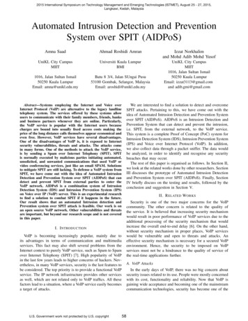
Chapter 1: Connecting the ApplianceThe G400 and G2000 Front and Back PanelsIntroductionThis topic identifies the front and back panels of the G400, G400 (Rev A)and G2000 appliances, along with descriptions for each item, includingthe external bypass unit.Identifying theG400 (Rev A)appliance modelTo determine the G400 (Rev A) appliance model, check the serial numberand model label. It should say “Model G400 Rev: A.”Note: The G400 (Rev A) hardware port configurations are the same as theG2000 model. Refer to the appropriate diagram for your appliance modelfor information about ports and external bypass connectivity.Front panel diagramand legendThe Proventia G400 and G2000 appliance front panel is shown inFigure 5:A BC DE FGHILKJFigure 5: G appliance front panelThe front panel of the Proventia G appliance includes the following:20 A - Kill Port LED B - Management Port LED C - Power Button (press and hold to shutdown) D - Power LED E - Hard Drive Activity LED F - Fault LED G - System ID LED H - System ID Button
The G400 and G2000 Front and Back Panels I - Reset Button J - USB (unused) K - Unused L - VideoCaution: You must operate this unit with the top cover installed to ensureproper cooling. A fault LED light generally does not indicate a problemwith the appliance itself. The light can appear if the power cord is notplugged in properly.Proventia G Intrusion Prevention Appliance Quick Start Guide21
Chapter 1: Connecting the ApplianceG400F back paneldiagramFigure 6 illustrates the back of a G400F appliance. USB ports are labeledas they correspond to the monitoring ports for external bypass unitconnectivity. For information on connecting the external bypass unit tothis appliance, see “Configuring the Appliance External Bypass Unit” onpage 32.Important: Refer to the G2000 diagrams if you have a G400 (Rev A)appliance.Figure 6: G400F back panel diagramNote: An additional USB card with two more USB ports is added foradditional G400 full fiber units (A and C).22
The G400 and G2000 Front and Back PanelsG400CF back paneldiagramFigure 7 illustrates the back of the G400CF copper-fiber appliance. TheUSB ports are labeled as they correspond to the monitoring ports forexternal bypass connectivity. Other ports and connections are the same asthe G400F back panel. Refer to Figure 6, “G400F back panel diagram” onpage 22. For more information about external bypass connections, see“Configuring the Appliance External Bypass Unit” on page 32.Important: Refer to the G2000 diagrams if you have a G400 (Rev A)appliance.Figure 7: G400CF back panel diagramProventia G Intrusion Prevention Appliance Quick Start Guide23
Chapter 1: Connecting the ApplianceG400C andG2000C back paneldiagramThe following diagram describes the G400C or G2000C all-copperappliance. The Proventia G400C, G400C (Rev A) and G2000C applianceshave built-in copper bypass hardware, which by default fails “open,”allowing traffic to continue passing through the appliance if the appliancefails or loses power. If you change the default setting to closed, theappliance will not allow traffic to pass in the event of a failure.Figure 8: G400C/G2000C back panel diagram24
The G400 and G2000 Front and Back PanelsG400F (Rev A) andG2000F back paneldiagramThe following diagram describes the G400F (Rev A) or G2000F fiberappliance. USB ports are labeled as they correspond to the monitoringports for external bypass unit connectivity. For information on connectingthe external bypass unit to these appliances, see “Configuring theAppliance External Bypass Unit” on page 32.Figure 9: G400F (rev A) or 2000F back panel diagramNote: An additional USB card with two more USB ports is added foradditional G400 (Rev A) or G2000 full fiber units (C and A).Proventia G Intrusion Prevention Appliance Quick Start Guide25
Chapter 1: Connecting the ApplianceG400CF (Rev A) or2000CF back paneldiagramFigure 10 shows the back of the G400CF (Rev A) or G2000CF copper-fiberappliance labeled for external bypass unit connectivity. USB ports arelabeled as they correspond to the monitoring ports. For bypass unitconnectivity information, see the “Configuring the Appliance ExternalBypass Unit” on page 32.Figure 10: G400CF (rev A) or 2000CF back panel diagram26
Standard Inline Deployment ScenariosStandard Inline Deployment ScenariosIntroductionThe Proventia G400C, G400C (Rev A) and G2000C appliances have builtin copper bypass hardware, which by default fails “open,” allowingtraffic to continue passing through the appliance if the appliance fails orloses power. If you change the default setting to closed, the appliance willnot allow traffic to pass in the event of a failure.The G400F, G400CF, G400F (Rev A) G400CF (Rev A) and G2000F andG2000CF do not have built-in bypass hardware. You can purchase anoptional fiber bypass unit and kit that provides bypass functionality.Contact Internet Security Systems for availability. See “Configuring theAppliance External Bypass Unit” on page 32 for more information.Note: These models require the external bypass unit for the fiber portsonly.Caution: You should install the correct network cabling and verify thattraffic flows before you turn on the appliance.Cabling guidelinesPlace a CAT5 crossover cable between a Proventia G appliance and aserver or a workstation. ISS recommends using a CAT5 crossover cablebetween a Proventia G appliance and a router. A straight cable issufficient between a Proventia G appliance and a switch or hub.Note: Where a crossover is needed, you may use your own CAT5crossover cable or the provided one-foot cable and crossover coupler thatcomes with the appliance. When the appliance is not running, itsmonitoring ports function as a crossover. The following scenarios workindependently of the monitoring port (A or B) you use.Proventia G Intrusion Prevention Appliance Quick Start Guide27
Chapter 1: Connecting the ApplianceSwitch/Hub1 toSwitch/Hub2When you deploy the appliance between two switches or hubs, establishstraight-through connections using CAT 5 cable from Switch1/Hub1 tothe appliance and from the appliance to Switch2/Hub2, as shown inFigure 11:Figure 11: Inline deployment scenario, switch/hub to switch/hubWorkstation/Server to RouterWhen you deploy the appliance between a workstation/server and arouter, establish a CAT5 crossover connection from the workstation/server to the appliance. Establish a crossover CAT 5 connection from theappliance to the router as shown in Figure 12:Figure 12: Inline deployment scenario, workstation/server to routerWorkstation/Server to Switch/HubWhen you deploy the appliance between a workstation/server and aswitch/hub, establish a CAT5 crossover connection from theworkstation/server to the appliance. Establish a straight cable connectionfrom the appliance to the switch/hub as shown in Figure 13:Figure 13: Inline deployment scenario, workstation/server to switch/hub28
Standard Inline Deployment ScenariosRouter to Switch/HubWhen you deploy the appliance between a router and a switch/hub,establish a CAT5 crossover connection from the router to the appliance.Establish a straight cable connection from the appliance to the switch/hub as shown in Figure 14:Figure 14: Inline deployment scenario, router to switch/hubRouter to RouterWhen you deploy the appliance between two routers, establish a CAT5crossover connection from Router 1 to the appliance, and from theappliance to Router 2, as shown in Figure 15:Figure 15: Inline deployment scenario, Router to RouterHigh AvailabilityDeploymentAppliances cannot be configured for high availability (HA) mode duringthe initial setup in the Proventia Setup Utility. Select one of the standardappliance modes during the initial setup, and then refer to HighAvailability Configuration topics in the Proventia G Intrusion PreventionAppliances User Guide or the Help for detailed procedures for enabling HAmodes.Proventia G Intrusion Prevention Appliance Quick Start Guide29
Chapter 1: Connecting the ApplianceConnecting the Cables and Starting the ApplianceIntroductionThis topic provides instructions for connecting cables and starting theappliance for the first time.Important: Ensure that you keep your management and monitoringcommunication separate so that network traffic will be allowed to passuninterrupted through the appliance’s network interface card (NIC).Connecting thepower cordThe appliances have dual standard AC power connectors.To connect the power cord(s):1. Press the strain relief into the platform hole until it snaps into place.2. Insert the power cord into the loop.Note: Leave some slack in the power cord between the strain reliefand the power supply.3. Pull the tab to secure the power cord in the loop.4. Plug one end of the power cord into the back of the ap
Seagate Crystal Reports, Seagate Info, Seagate, Seagate Software, and the Seagate logo are trademarks . Download the license key file from the ISS Registration Center to your computer. Note: ISS recommends that you upload the license key file to a designated directory so that the appliance can download and install