Transcription
Motor-Operated Valves Course Manual2.4Theory of Operation of Motor-Operated ValvesRotork Type NA actuators areSyncrosetwatertight/explosion-proofactuators developed for installation in thecontainment of a nuclear power plant.Special seals and materials are used in manyof the components, otherwise the actuatorsare identical to the Type A or non-nuclearactuators.Rotork ActuatorsIntroductionA limited number of U.S. plants useRotork actuators.Rotork Controls isheadquartered in Bath, England, with itsNorth and South America manufacturingfacilities located in Rochester N.Y. RotorkMotorized Valve Operators (MOV'S) allowfor local or remote positioning of a valve viaan electrical motor which is part of theactuator.Before attempting any repair on anuclear (NA) type actuator, Rotork shouldbe consulted for problem diagnosis andparticular attention should be paid tomaintaining the nuclear qualification of theactuator. Please refer to Rotork in all casesfor spare parts.Control components can be adjustedso that the valve can be made to stroke andstop once a predetermined position isreached or a certain amount of thrust hasbeen attained. The valve itself is notmanufactured by Rotork Controls, althoughthe characteristics of the valve must beconsidered in the selection of the controlcomponents, control adjustments, and theactuator sizing.Rotork recommends no periodicpreventive maintenance except for an annuallubrication level inspection.NOTE: Due to the fact that Rotork Controlsis a British company, some of the terms usedfor component description may beunfamiliar to most Americans.The Rotork maintenance philosophyrecommends modular replacement ofcomponents rather than replacement ofindividual pieces. Rotork actuators areguaranteed for one year from date ofshipment and while under warranty shouldbe repaired by Rotork field personnel. Insome instances the warranty may beextended for up to two years if a Rotorkfield representative is present for actuatormounting and startup.USNRC Technical Training CenterGlossaryACTIVE - Describes an actuator applicationthat must operate during a reactoremergency.ADD-ON-PAK (AOP) - A subassembly thatcan be fitted to either syncropak or syncrosetactuators as an extension of the switchmechanism.2-6705/10
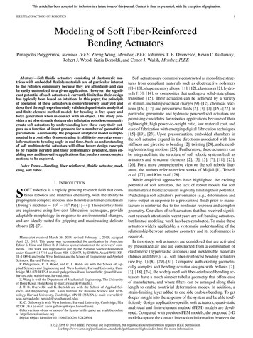
Motor-Operated Valves Course ManualTheory of Operation of Motor-Operated ValvesSYNCROPAK - Rotork designation for anactuator having all the electrical componentsnecessary for operation mounted on theactuator. Refer to provided training aid.BELLEVILLE SPRING - A dish-shapedwasher made from spring steel, stacked toallow for compression. A stack of Bellevillesprings is referred to as a BELLEVILLESPRING PACK, or just a spring pack.SYNCROSET - Rotork designation for anactuator having most of the electricalcomponents necessary for operation locatedremotely from the actuator. Refer to Figure2-54.BUNG- Rubber or plastic plug.DRIVE BUSH - The actuator connection tothe valve stem; the drive bush is actuallythreaded or bored and keyed.The nuclear sizes of Rotork actuatorsare listed in Table 2-10 along with theiravailable output torque values.HELIX - The method used to convert linearmotion to rotary motion on the torque driveof the switch mechanism.IMPACT HAMMER BLOW - Designed"free-play" in an actuator to allow the motorto reach full speed before moving the valvestem.NEMA - National Electrical ManufacturersAssociation.PASSIVE - Describes an actuatorapplication that must maintain structuralintegrity during and immediately followinga reactor emergency.SEL-LOC PIN - Self-locking pin (roll pin).SWITCH MECHANISM - The assembly ina Rotork actuator that houses the torque andlimit switch contacts, auxiliary contacts, andthe torque helix.USNRC Technical Training Center2-6805/10
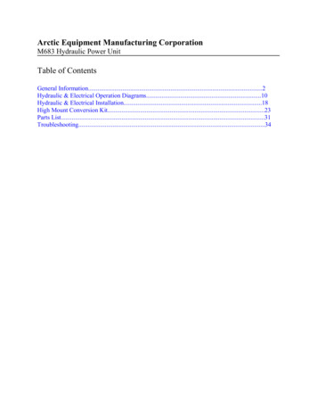
Motor-Operated Valves Course ManualTheory of Operation of Motor-Operated ValvesThe two general categories that theactuators fall into are as follows:Category 1 - sizes 7 and 11Category 2 - sizes 14, 16, 30, 40, 70 and 90.Actuators within a given categoryare similar except for physical size andavailable output torque, however, the twogeneral categories principle of operation areclosely related.Motor Operation1.Principles of Operation2.See Figures 2-55, 2-56, 2-57 and 2-58.Except where noted, the size of Rotorkactuators addressed in this chapter are thoseidentified previously as being in Category 2.Although the 70 and 90 size actuators differslightly from the others, these differenceswill be pointed out during the discussion.USNRC Technical Training Center2-69When the motor is energized, themotor shaft (wormshaft) rotates. Thewormshaft is engaged with thewormwheel on the center column.The wormwheel driven by the motorwormshaft rotates on the centercolumn. The drive pins located ontop of the wormwheel engage thelower portions of the clutch keysrecessed in machined keyways onthe center column. The clutch keystransmit the force from thewormwheel to the center column.05/10
Motor-Operated Valves Course ManualTheory of Operation of Motor-Operated Valvespower to the motor. The limit switchassembly is driven by a wormlocated on the center column.5.3.4.The center column drives the drivebush through lugs located on thebottom of the center column. Thedrive bush is threaded internally tomatch the threads on the valve stem.Rotating the drive bush opens orcloses the valve.When the valve reaches the fullstroke position (open or closed), theswitch mechanism de-energizes themotor control circuit to interruptUSNRC Technical Training Center6.2-70In the event of an excessive torquecondition or in "torque-shut"applications, the threading force ofthe wormshaft overcomes Bellevillespring compression and "walks" thewormwheel. The movement of thewormshaft actuates the torque switchthrough the torque shaft. Theactuation of the torque switch deenergizes the motor control circuit tointerrupt power to the motor. Torqueswitch actuation on 70/90 actuatorsis by torque shaft movement througha ratio plate located at the rear of theswitch mechanism.When reversing direction, theactuator has an impact hammer bloweffect. The motor is allowed toachieve full rated speed before itengages with the center column.05/10
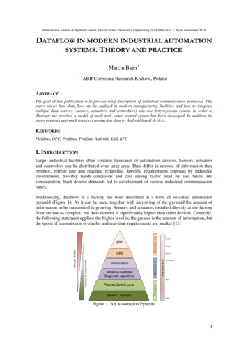
Motor-Operated Valves Course ManualTheory of Operation of Motor-Operated ValvesActuators with no lost motion on thecenter column (instead of the impacthammer blow effect) are available ifrequested.NOTE: The actuator motor must beenergized to return the actuator to motoroperation.6.Manual Operation1.2.3.To operate the actuator in manual,the hand/auto lever is depressed.The hand/auto lever rotates thehand/auto cam to raise the yoke endand clutch ring. The clutch keys areraised away from the pins on thewormwheel by the clutch ring.The top portions of the clutch keysare engaged by cap screw heads onthe bottom of the handwheel.Rotation of the handwheel will thenrotate the center column through thekeys.Valve operating thrust does not exertforce on the actuator drive gearing.A thrust base is used on Rotorkactuators except on the lower casingsize (7/11) and on non-thrustapplications. The thrust base isbolted to the bottom of the actuatorcasing.Manual OperationActuatorsforCategory1Refer to Figure 2-59.NOTE: On the 70/90 size actuators, theclutch keys do not extend above the clutchring. Instead, hand drive screws are threadedinto the top of the clutch ring.4.5.When the yoke end is raised, thehand/auto finger is pivoted by springtension to sit on the wormwheel andhold the actuator in manual.When the motor is energized, thewormwheel begins rotation. Thehand/auto finger (resting on thewormwheel) is carried out ofposition, allowing the clutch ring andclutch keys back onto thewormwheel.USNRC Technical Training CenterNOTE: The only significant differencebetween a Category 1 and a Category 2actuator is the declutching mechanism, and2-7105/10
Motor-Operated Valves Course ManualTheory of Operation of Motor-Operated Valvesfor that reason the following explanation isincluded.NameplateOptions1.Nameplate Information2.3.4.5.To operate the actuator in manual,the hand/auto lever is depressed.The hand/auto lever pivots thehand/auto jack to raise the clutchring and clutch keys away from thelugs on the wormwheel.The top portions of the clutch keysare engaged by cap screw heads onthe bottom of the handwheel.Rotation of the handwheel will thenrotate the center column through theclutch keys.When the hand/auto jack is pivotedto raise the clutch ring, the springfinger and finger stud are pivoted tosit on the wormwheel and hold thehand/auto jack, clutch ring, andclutch keys away from thewormwheel against the clutch springtension.When the motor is energized, thewormwheel begins rotation. Thespring finger and finger stud (restingon the wormwheel) are carried out ofposition, allowing the clutch ring andclutch keys back onto thewormwheel.andRotorkSerial NumberThe serial number on the actuatornameplate is specific to that unit. It is givento the actuator at the factory and shouldalways be included in the data recorded forpositive identification.Wiring Diagram NumberThe wiring diagramnumberidentifies the electrical characteristics of thecontrol system and motor. The diagramnumber should be supplied to factorypersonnel if questions or problems ariseconcerning the actuator control circuitry orelectrical components.Actuator Type - NuclearRotorkelectricmotor-drivenactuators are classified into three types: NA1, NA-4, and NA-5. The type NA-1 actuatoris used for active applications inside thecontainment, while the NA-4 is used insidethe containment for passive applications.The NA-5 actuator is used outside thecontainment in active applications. Tofurther describe the NA actuator types, it isnecessary to define the following terms:NOTE: The actuator motor must beenergized to return the actuator to motoroperation.USNRC Technical Training CenterInformation2-7205/10
Motor-Operated Valves Course ManualTheory of Operation of Motor-Operated ValvesACTIVE: Applications required tooperate during a reactor emergency.LubricantThe type of lubricant supplied by thefactory will be shown. The factorydetermines the lubricant based onrequirements supplied by the customer. Thelubricant type should not be changedwithout Rotork approval.PASSIVE: Applications that mustmaintain structural integrity during andimmediately following a reactor emergency.Actuator Type - Non-NuclearNon-nuclear electric motor-drivenRotork actuators are classified as A-typeactuators. A-type non-nuclear actuators aresimilar in design and construction to thenuclear Rotork actuators.HorsepowerThis number designates motorhorsepower (hp). Rotork actuators are sizedand rated according to torque and thrustoutput rather than motor horsepower.Output SpeedThe output speed of the actuator isspecified in rpm's. The output speed isspecified by the customer when the actuatoris initially ordered.Min - Duty RatingThe number in the "Min" block onthe Rotork nameplate corresponds to theduty rating (in minutes) of the actuator. Thisduty rating corresponds to the amount oftime the actuator can operate per hour, at anaverage running torque of 33% of maximumseating torque, without exceeding theallowable temperature increase over ambientconditions. Running the actuator longer thanthe stated duty cycle may cause the motorinsulation to break down.NEMA EnclosureThe NEMA enclosure ratingdescribes the environmental application forwhich the actuator housing (enclosure) isapproved. Rotork actuators are supplied asstandard with NEMA 6 watertight andexplosion-proof enclosures and are capableof electric operation in up to 10 feet of waterfor 48 hours provided the conduit entries aresealed.Motor SupplyThe motor supply identificationdescribes the electric power the actuatoruses for operation.Rotork actuators can be supplied tomeet other specifications when requested bythe customer.USNRC Technical Training Center2-7305/10
Motor-Operated Valves Course ManualTheory of Operation of Motor-Operated ValvesAuxiliary Switch RigMotor BrakesThe auxiliary switch rig section ofthe actuator nameplate designates theoperating voltage and current ratings (forboth AC and DC) of the control circuitfunctions.Torque-limiting motor brakes areoptional on Rotork actuators. Actuatorshaving the torque-limiting brake areidentified by the letter "T" in their modeldesignation, e.g., 16 NAT 1.Options Available with Rotork ActuatorsThrust-Absorbing Spring PacksDrive BushesA thrust-absorbing spring packconsisting of Belleville springs is alsoavailable on Rotork actuators. Wheninstalled, this spring pack is located in thethrust base of the actuator. The spring packabsorbs thrust in fast-acting, high-thrustactuators or those subjected to large thermaltransients.The output drive bush of a Rotorkelectric motor-driven actuator is available infour variations:1.2.3.4.Type A - Made of aluminum bronze,used for normal size valve stems (allactuators).Type AZ - Made of aluminumbronze, used for larger valve stemdiameters than the Type A canaccommodate.Type AR - Made of mild steel, usedfor non-thrust drives in size 40actuators and above. The AR bush isfor non-rising stem applicationsonly. (It is typically used for gearboxinput drives.)Type AB - Bush not supplied byRotork,usedfornon-thrustapplications only. The drive sleeve isbored and keyed at the output; twokeyways are optional. The Type ABdrive is available for the NA-1, NA4, NA-5, 7A, and 11A actuatorsonly.USNRC Technical Training CenterHandwheel DriveRotork valve actuators have asstandard a 1:1 handwheel drive ratio exceptfor sizes 70 and larger, which have a 15:1drive ratio. As an option, higher handwheelgear ratios are available for sizes 14 through90.Add-on-Pak 1Refer to Figure 2-60. Add-on-Pak 1(AOP 1) is a standard Rotork subassemblywhich can be fitted to either syncropak orsyncroset actuators as an extension of theswitch mechanism. The AOP 1 comprisesthe following components:2-7405/10
Motor-Operated Valves Course Manual1.2.3.4.5.Theory of Operation of Motor-Operated ValvesSet of gears for continuous localindication.Position indicator.Potentiometer for remote positionindication.Six changeover switches.Extension housing and calibrateddial.FolomaticFolomatic is a proportional controlcircuit for Rotork actuators. It enables asyncropak actuator to control the position ofa valve in proportion to a continuous currentor voltage signal. The control circuit has afeedback signal from the actuator positionpotentiometer for signal error.NOTE: Items 3 and 5 mentioned above arenot shown on Figure 2-60.Syncropak or SyncrosetThe standard electrical circuitryassociated with a Rotork actuator isavailable in two variations. The syncropak isan electrical "canister" used to house all theelectrical components necessary for localoperation of the actuator. A syncrosetactuator has a terminal head only, and all thestandard electrical components are housed ina control cabinet, usually located in a motorcontrol cabinet. Syncropak actuators are notapproved for nuclear use.Traveling "Blinker"Millipot StabilizedTransmitterCurrentPositionA traveling light (blinker) isavailable for Rotork actuators. It can besupplied for installation on the switchmechanism or on AOP 1.The millipot stabilized currentposition transmitter (CPT) is used in RotorkA-range actuators to make the remoteindication signal compatible for datascanning and logging bycomputer systems.The CPT is installed in conjunction withAOP 1 and gives a 4/20 mA output signalproportional to valve position.USNRC Technical Training CenterValve Position Switch UnitThe valve position switch unit(VPSU) provides end position switchcontacts for manually operated valves. TheVPSU has three switches for each end of2-7505/10
Motor-Operated Valves Course ManualTheory of Operation of Motor-Operated Valves2.3.valve travel. The switches are enclosed in awatertight and/or explosion-proof housingalong with a handwheel drive. The VPSUreplaces the original valve handwheel.NOTE: The wiring diagram number shouldalso be provided if information about theelectrical components of the actuator isneeded.Supervisory Control CircuitsSupervisory control circuits with thefollowing features are available for thesyncropak actuators:1.2.3.4.5.Actuator ComparisonsThe Rotork Type NA actuator andthe Limitorque Type SMB actuator aresimilar in that they are both motorizedactuators that will operate valves bysupplying the necessary force to a stem orinput shaft to reposition the valve's internals.Both have the capabilities of allowing forlocal or remote operation of a valve whilemonitoring its position, providing local andremote indication, over thrust protection andother control features.Incomplete travel alarm.Unauthorized manual operation.Exact end position indication.Availability monitoring.Fault analysis.SummaryThe actuator output torque, thrust,and speed depend on the motor speed, motorhorsepower input into the actuator, and thegearing inside the actuator. Since there areso many variables associated with theactuator motor ratings, gearing, andelectrical components, it is evident thatRotork actuators or components should notbe interchanged among applications withoutconsulting Rotork.Despite their similarities, the RotorkType NA and the Limitorque Type SMBhave several distinct differences as follows:1.2.When or if it becomes necessary toconsult with Rotork about an actuator, thefollowing information (as a minimum) mustbe known:3.1.Actuator type. e.g. Nuclear (NA) orNon-nuclear (A)USNRC Technical Training CenterActuator serial numberActuator size. e.g. 7, 11 or 142-76UnlikeLimitorque,Rotorkrecommends modular replacement ofcomponents rather than individualpieces.The Belleville springs on the Rotorkare located behind the motor's statorrotor unit, whereas on the Limitorquethey are situated behind the worm.The Rotork has only one gearingarrangement, that being between theworm and wormwheel. Limitorque05/10
Motor-Operated Valves Course Manual4.5.6.7.Theory of Operation of Motor-Operated Valveshas two gearing arrangements, onebetween the motor pinion andwormshaft gear (wormshaft clutchgear on the SMB-0 through 4) withthe other being between the wormand worm gear.Rotork uses a thrust ring and a thrustpad on the top portion of the centercolumn (Category 2 actuators) and abearing on the lower portion of thecenter column to absorb radial andaxial thrust loads, while Limitorqueemploys tapered roller bearings onboth the top and bottom of its drivesleeve for the same purposes.Rotork (Category 2 actuators)utilizes a yoke with a hand/autofinger attached to maintain theactuator in manual. Limitorque usestwo trippers to accomplish the same.Rotork Type NA actuators arecategorized as watertight andexplosion-proofwhiletheLimitorque Type SMB actuators arenot.The torque and limit switches on theLimitorque Type SMB actuators areseparate components as opposed tothe Rotork Type NA actuators whichcombines the two into one deviceknown as the switch mechanism.USNRC Technical Training Center2-7705/10
Motor-Operated Valves Course ManualUSNRC Technical Training CenterTheory of Operation of Motor-Operated Valves2-7805/10
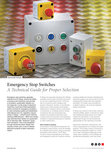
Motorized Valve Operators (MOV'S) allow for local or remote positioning of a valve via an electrical motor which is part of the actuator. Control components can be adjusted so that the valve can be made to stroke and stop once a predetermined position is reached or a certain amount of thrust has been attained. The valve itself is not