Transcription
INSTALLATIONINSTRUCTIONSEALED COMBUSTIONDOWNFLOW GAS FURNACEMODELS: DGAA, DGAH, DGPA, AND DGPHTABLE OF CONTENTSFURNACE SPECIFICATIONS . . . . . . . . . . . . . . . . .2GENERAL INFORMATION . . . . . . . . . . . . . . . . . . . .3INSTALLATION STANDARDS . . . . . . . . . . . . . . . . .3CODE COMPLIANCE . . . . . . . . . . . . . . . . . . . . . .3HIGH ALTITUDE INSTALLATION . . . . . . . . . . . .3MINIMUM FURNACE CLEARANCES . . . . . . . . .3RETURN AIR REQUIREMENTS . . . . . . . . . . . . . . . .4CLOSET INSTALLATIONS . . . . . . . . . . . . . . . . . .4AIR DISTRIBUTION SYSTEMS . . . . . . . . . . . . . .4ROOF JACK . . . . . . . . . . . . . . . . . . . . . . . . . . . . . . .6EXISTING FURNACE REPLACEMENT . . . . . . . .6NEW HOME INSTALLATION . . . . . . . . . . . . . . . .6INSTALLATION IN SNOW REGIONS . . . . . . . . .6LOCATING AND CUTTING ROOF JACKOPENING . . . . . . . . . . . . . . . . . . . . . . . . . . . . . . .6INSTALLING ROOF JACK IN ROOF . . . . . . . . . .6DUCT CONNECTORS . . . . . . . . . . . . . . . . . . . . . . .9INSTALLATION OF SCREW ATTACHMENTDUCT CONNECTOR . . . . . . . . . . . . . . . . . . . . .10INSTALLATION OF TAB ATTACHMENTDUCT CONNECTORS . . . . . . . . . . . . . . . . . . . .10INSTALLATION OF THE FURNACE . . . . . . . . . . .11CEILING RINGS . . . . . . . . . . . . . . . . . . . . . . . . .12ELECTRICAL WIRING . . . . . . . . . . . . . . . . . . . . . .12CONNECT POWER SUPPLY WIRES . . . . . . . .12CONNECT THERMOSTAT WIRES . . . . . . . . . .12WALL THERMOSTAT . . . . . . . . . . . . . . . . . . . . .13For Installation In:1.Manufactured (Mobile) Homes2.Recreational Vehicles & Park Models3.Modular Homes & BuildingsIMPORTANT - Only individuals having proven experience with thistype of equipment should attempt to perform set-up.Proper furnace set-up and adjustment is the responsibility of theretailer/homeowner and is not covered under warranty.FURNACE START-UP CHECK LIST Has roof jack crown been correctly installed? Has furnace gas valve and burner orifice been correctly converted for Propane. gas where applicable?GAS PIPING . . . . . . . . . . . . . . . . . . . . . . . . . . . . . .19 INSTALLATION AND CHECKING OF GAS LINE 19HIGH ALTITUDE DERATION CHART . . . . . . . .21Has furnace gas valve been de-rated for altitudes above 2000feet where applicable? Is gas line outlet pressure properly set for fuel type? (natural gasis 3.5" W.C.; Propane is 10" W.C.)REPAIR PARTS LIST . . . . . . . . . . . . . . . . . . . . . . .22 Is cross-over duct installed per home builder and UPG installation instructions? Has furnace been operated through a complete heating cycle? Has the pilot flame been adjusted properly? (DGPH and DGPAModels)WIRING DIAGRAMS . . . . . . . . . . . . . . . . . . . . . . .14CAUTION: READ ALL SAFETY GUIDES BEFOREYOU START TO INSTALL YOUR UNIT.SAVE THIS MANUAL035-16328-002 Rev. C (0902)
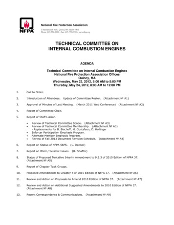
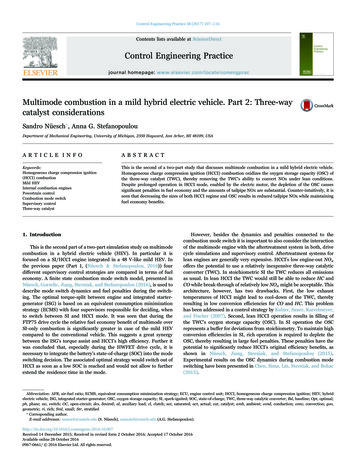
035-16328-002 Rev. C (0902)FURNACE SPECIFICATIONSDGAA — AUTOMATIC IGNITION — WITH BUILT-IN COIL CABINET — 4 TON - A/C READYMODEL tory Equipped for use withNATURAL GASNATURAL GASNATURAL GASNATURAL ,00056,00062,00072,000DGPA — STANDING PILOT — WITH BUILT-IN COIL CABINET — 3 TON - A/C ATURAL GASNATURAL GASNATURAL GASNATURAL 0DGPH — STANDING PILOT — WITH BUILT-IN COIL CABINET — 3 TON - NO A/C TANATURAL GASNATURAL GASNATURAL GASNATURAL 0DGAH — AUTOMATIC IGNITION — HEATING ONLY — NO COIL CABINETDGAH056BBSADGAH077BBSANATURAL GASNATURAL GAS56,00077,00045,00062,000ELECTRICAL SPECIFICATIONSElectrical Power SupplyBreaker or FuseThermostat CircuitNominal Anticipator SettingGas Valve Inlet115 Volts - 60 Hz - 1 Phase15 Amp24 Volt - 60 Hz - 40 VA.501/2" ”23”12”9-3/4”12”76”59-1/2”DGAH SeriesDGPH, DGPA & DGAA SeriesFIGURE 1 : Furnace Dimensions2Unitary Products Group
035-16328-002 Rev. C (0902)GENERAL INFORMATIONNOTE: The words “Shall" or “Must" indicate a requirementwhich is essential to satisfactory and safe product performance.The words “Should" or “May" indicate a recommendationor advice which is not essential and not required butwhich may be useful or helpful.IMPORTANT - These instructions are primarily intended toassist qualified individuals experienced in the proper installation of heating and/ or air conditioning appliances. Some localcodes require licensed installation service personnel for thistype of equipment. Read all instructions carefully before starting the installation.Improper installation may damage equipment,can create a shock hazard, and will void the warranty.The furnace shall be installed so the electricalcomponents are protected from water.Recreational Vehicles in U.S.A.:1.Standard on Recreational Vehicles (NFPA 1192, formerlyNFPA 501C).2.National Electrical Code (NFPA 70).Recreational Vehicles in Canada:1.Unit installation shall comply with current CSA standardCAN/CGA-Z240.4.2 - Installation Requirements for Propane Appliances and Equipment in Recreational Vehicles.2.Unit electrical wiring and grounding shall comply withcurrent CSA standard C22.2 No.148/CAN/CSA-Z240.6.2- Electrical Requirements for recreational vehicles.HIGH ALTITUDE INSTALLATIONFor elevation above 2,000 feet, derate furnace input 4% foreach 1,000 feet of elevation above sea level. Derating isaccomplished by reducing the orifice size. See DeratingChart for orifice size.In Canada, for elevations from 2000 to 4500 feet derate byreducing gas manifold pressure to 3.0” W.C. for natural gasand 9.0” W.C. for LP gas.The furnace is not to be used for temporary heating of buildings or structures under construction.Do not test the fuel system at more than 14inches water column after furnace has been connected to the fuel line. Such testing may void thewarranty. Any test run above 14 inches water column may damage the furnace control valvewhich could cause an explosion, fire, or asphyxiation.INSTALLATION STANDARDS Never attempt to alter or modify this furnace or anyof its components. Never attempt to repair damaged or inoperablecomponents. Such action could cause unsafe operation, explosion, fire and/or asphyxiation. If a malfunction has occurred, or if you feel that thefurnace is not operating as it should, contact a qualified service agency or gas utility for assistance.CODE COMPLIANCEMINIMUM FURNACE CLEARANCESThe installer must comply with all local codes and regulationswhich govern the installation of this appliance. Local codesand regulations shall take precedent over these regulationswhere applicable. In lieu of local codes, the appliance shallbe installed in accordance with one or more of the followingstandards.Access for servicing is an important factor in the location ofany furnace. A minimum of 24 inches should be provided infront of the furnace for access to the heating elements andcontrols. This access may be provided by a closet door or bylocating the furnace 24 inches from a facing wall or partition.Manufactured homes in the U.S.A.:1.Federal Manufactured Home Construction & SafetyStandard (H.U.D. Title 24, Part 3280).2.National Fuel Gas Code (ANSI-Z223.1, NFPA-54).3.National Electrical Code (NFPA 70).Manufactured homes in Canada:1.Natural Gas and Propane Installation Code (CAN/CSAB149.1).2.Canadian Electrical Code, Part 1 (CSA C22.1)Unitary Products GroupThese furnaces are design certified for the following minimumclearances from combustible material in alcove or closetinstallationTable 1: MINIMUM NT6”24”TOP2”2”ROOF JACK0”0”DUCT0”0”3
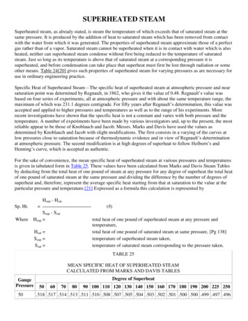
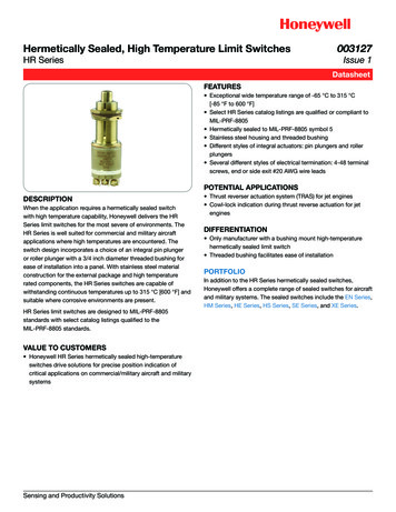
035-16328-002 Rev. C (0902)RETURN AIR REQUIREMENTS6.Non-combustible pans having one-inch upturned flangesare located beneath openings in the floor return ductsystem.Additional Requirements7.Additional requirements for floor and ceiling return system forcloset installed sealed combustion heating appliance aregiven in the next paragraph.Wiring materials located in the return duct system conform to Article 300-22 (B&C) of the National ElectricalCode (NFPA-70).8.Gas piping is not run in or through the return duct system.9.The negative pressure in the closet as determined bytest with the air-circulating fan operating at high heatingspeed and the closet door closed is to be not more negative than minus 0.05-inch water column.CLOSET INSTALLATIONSFloor or Ceiling Return Air SystemListed in the next paragraph are the conditions to be met byManufactured Home Manufacturers to have U.L. acceptanceof in-floor or ceiling return air systems of closet installeddirect vent forced air heating appliances for ManufacturedHomes to be sold in the United States.1.The return-air opening into the closet, regardless of location, is to be sized not less than specified on the appliance's rating plate.2.If the return-air opening is located in the floor of thecloset (versus the vertical front or side wall), the openingis to be provided with means to prevent its inadvertentclosure by a flat object placed over the opening.3.4.5.The cross-sectional area of the return duct system (whenlocated in the floor or ceiling of the manufactured home)leading into the closet is to be not less than that of theopening specified on the appliance's rating plate.The total free area of openings in the floor or ceiling registers serving the return-air duct system is to be not lessthan 150% of the size of the opening specified on theappliance's rating plate. At least one such register is tobe located where likelihood of its being covered by carpeting, boxes, and other objects is minimized.Materials located in the return duct system have a flamespread classification of 200 or less.ASingle trunk duct4CrossoverHAZARD OF ASPHYXIATION, DO NOT COVEROR RESTRICT FLOOR OPENING.AIR DISTRIBUTION SYSTEMSFor proper air distribution, the supply duct system shall bedesigned so that the static pressure does not exceed thelisted static pressure rating on the furnace rating plate.Three typical distribution systems are illustrated in Figure 2.Location, size and number of registers should be selected onthe basis of best air distribution and floor plan of the home.The Air Temperature Rise is to be adjusted to obtain a temperature rise within the range(s) specified on the furnace rating plate.CTransition Duct with BranchesB*Dual trunk duct with crossover connector1Dual trunk duct10. For floor return systems, the manufactured home manufacturer or installer shall affix a prominent marking on ornear the appliance where it is easily read when thecloset door is open. The marking shall read:2Transition ductBranches31. Crossover Duct must be centered directly under furnace.2. Use 12” Diameter Round or insulated Flex-duct only.3. Terminate Flex-duct (opposite furnace) in the center of the trunk duct.4. Flex-duct material must be pulled tight — No Loops or unnecessary dips — Air Flow may be impeded.FIGURE 2 : Air Distribution Systems4Unitary Products Group
035-16328-002 Rev. C (0902)Furnace to Closet Door Clearance —5 Inches or moreReturn Air Grille Part No.7900-287P/A * WhiteThe closet door MUST have a minimum of 250 Square Inchesof free area in the upper half of the door.If opening for return air is located in the floor or sidewalls andbelow the top of the furnace casing:A250 SQ. IN.MINIMUMFREE AREA1. 6 inches minimum clearance must be provided on sidewhere return is located, and2. 6 inches minimum clearance must be maintained from thefront of furnace.B250 SQ. IN.MINIMUMFREE AREA50 SQ. IN.MINIMUMFREE AREACLOSETFURNACE5”or greater * Closetto Door ClearanceDOORReturn Air Closet Door Part No.7900-7771/C * WhiteFIGURE 3 : Closet To Door Clearance - 6” or GreaterFurnace to Closet Door Clearance —Greater than 1 Inch and Up to 5 Inches1. The closet door MUST have a minimum of 250 Square Inchesof free area in the upper half of the door and a minimum of50 Square Inches of free area in the lower area of the door.The lower closet door grille may be omitted if an undercut of2-1/2 inches is provided in the door.250 SQ. IN.MINIMUMFREE AREA50 SQ. IN.MINIMUMFREE AREA2. A fully louvered closet door MUST have a minimum of 250Square Inches of free area in the upper half of the door.B250 SQ. IN.MINIMUMFREE AREAAs an option to the lower grill,an undercut of 2-1/2" will provide50 Square. Inches of free area.FIGURE 4 : Furnace To Closet Door Clearance - 1” To 6”Furnace to Closet Door Clearance —Less than 1 Inch250 SQ. IN.MINIMUMFREE AREAThe closet door MUST have three return air grilles. Thetotal free area of the two upper grilles must be minimumof 250 Square Inches. The total free area of the lowergrille MUST be a minimum of 50 Square Inches.The grilles MUST BE ALIGNED directly opposite thereturn air grille of the furnace door.50 SQ. IN.MINIMUMFREE AREAFIGURE 5 : Furnace To Closet Door Clearance - Less Than 1”Unitary Products Group5
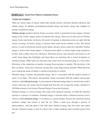
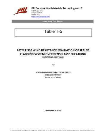
035-16328-002 Rev. C (0902)ROOF JACKNEW HOME INSTALLATIONIf this furnace is installed on a new home do the following:1.Inspect the furnace top collars for signs of insulation orceiling debris which might have fallen in during cutting ofthe ceiling and roof holes. Remove all debris before continuing.2.Only use the appropriate roof jack. See Figures 6& 7 for correct application.After unpacking the roof jack, check the rain caps. Insurethey are not damaged, tilted or crooked. Do not twist,crush or sit on the roof caps during installation. Damagedroof caps will cause improper furnace operation. The furnace will not heat properly and could result in explosion.3.Do not exceed the maximum height as determined from Figures 6 & 7. Installer should allowan additional 1-1/2" travel before the flue pipeassembly is fully extended against the built-instop. This provides an additional safeguardagainst the flue assembly being pulled from theroof jack during transportation or other stressconditions.Before inserting the vent pipe into the furnace top,inspect the furnace flue and combustion air opening fordebris or insulation which have fallen in during pre-installation steps. Do not proceed unless all debris have beencleaned out or removed.4.After installing roof jack on furnace top collar, check tomake sure there is no gap in back or side between thepipe collar and the furnace casing top. If necessary toprevent excessive air leakage, the installer should sealjoints in the combustion air tube with aluminum type orother suitable sealant.Failure to follow all venting instructions can resultin fire, asphyxiation, or explosion.EXISTING FURNACE REPLACEMENTIf this furnace replaces an existing furnace, do the following:INSTALLATION IN SNOW REGIONS1.If a 2nd roof, roof cap or addition has been made to theexisting roof of the home, remove the old roof jack completely! To avoid the possibility of an improperly installedpipe or gaps in the old roof jack, INSTALL A NEW ROOFJACK. Your ceiling and roof height will determine the correct roof jack to use. Refer to the vent selection table, ofthe furnace installation instructions.When the combustion air pipe inlet is covered or blocked withsnow, the furnace will not operate properly due to thedepleted combustion air supply.After unpacking the roof jack, check the rain caps. Insurethey are not damaged, tilted or crooked. Do not twist,crush or sit on the roof caps during installation. Damagedroof caps will cause improper furnace operation. The furnace will not heat properly and could result in explosion.LOCATING AND CUTTING ROOF JACK OPENING2.3.Before inserting the roof jack into the furnace top,inspect the furnace flue and combustion air opening fordebris or insulation which might have fallen in during preinstallation steps. Do not proceed unless all debris hasbeen cleaned out or removed.4.After installing roof jack on furnace top collar, check tomake sure there is no gap in back or side between thepipe collar and the furnace casing top.5.Use only the pipes provided with the roof jack assembly.Do not add to or adapt other sheet metal pipes. Do notcut, insert or add other pipes to this assembly.6.6In no case should there be a gap between sections ofthe flue pipe or the combustion air pipe. If necessary toprevent excessive air leakage, the installer should sealjoints in the combustion air tube with aluminum type orother suitable sealant.Therefore, if the furnace will be located in regions wheresnow accumulation on the roof exceeds 7" or in H.U.D. SnowLoad Zones, a roof jack extension (Part No. 7680B6541) isrecommended.To facilitate the proper installation of the roof jack, it is veryimportant that the roof jack opening in the ceiling and roof beon the same vertical center line as the furnace flue collar. SeeFigure 9.Mark this location on ceiling and scribe a circle with a 5"radius (10" diameter) around this mark. Cut opening for roofjack through ceiling and roof. (If furnace was installed duringconstruction, cover furnace and flue opening to preventdebris from entering flue when hole is cut for roof jack.)INSTALLING ROOF JACK IN ROOF(See Figure 6 & 7 for Dimensional requirements.)Insert roof jack into opening in the roof.The roof jack should be secured to the furnace before roofflange (flashing) is secured to the roof. This will insure a better alignment of the flue pipe and furnace flue collar. Caulkaround and under roof flange to provide a water tight seal,before securing roof jack flashing to roof.Unitary Products Group
035-16328-002 Rev. C (0902)SWIVEL FLASHINGADJUSTS FROM0/12 TO 5/12 PITCH12SLANTFLASHING3/12 PITCHDGAH FURNACESDGPH, DGPA, & DGAA FURNACESINSTALLATION DIMENSIONSINSTALLATION DIMENSIONS“A”ADJUSTABLE HEIGHT“B”ADJUSTABLE HEIGHT4000-7101/C4000-6101/A70” to 79”86” to 95”4000-7121/C4000-6121/A75” to 86”91” to 102”4000-7141/C4000-6141/A83” to 104”99” to 120”4000-7151/C4000-6151/A90” to 116”106” to 132”4000-7171/C4000-6171/A127” to 157”143” to 173””The 4084-7141 is dimensionally the same as 4000-7141/C and is available only in Canada.The 4084-7151 is dimensionally the same as 4000-7151/C and is available only in Canada.19 1/2"FLUEGASESCAREFULLY CAULK ALL AROUND SWIVEL JOINT WITHSEALANT SUPPLIED BY FURNACE MANUFACTURER.FLUEGASES19 ULKUNDERFLASHINGROOFThe End of Upper Portion of Roof Jack needNot extend below the ceiling.IMPORTANTSEAL ROOF JACK FLASHING TO THE ROOF JACKAND ROOF.THIS IS THE INSTALLER'S RESPONSIBILITY.BA76"59-1/2"DGPH, DGPA,DGAA, MODELSDGAH MODELSFLOORWARM AIR DUCTDUCT CONNECTORDUCT CONNECTORWARM AIR DUCTFIGURE 6 : Standard Roof JackUnitary Products Group7
035-16328-002 Rev. C (0902)SWIVEL FLASHINGADJUSTS FROM0/12 TO 5/12 PITCHSLANTFLASHING3/12 PITCHDGAH FURNACESDGPH, DGPA, & DGAA FURNACESINSTALLATION DIMENSIONSINSTALLATION DIMENSIONS“B”ADJUSTABLE HEIGHT“A”ADJUSTABLE HEIGHT4000-8161/C4000-9161/A85” to 101”101” to 117”4000-8181/C4000-9181/A99” to 129”115” to 145”CAREFULLY CAULK ALL AROUND SWIVEL JOINT WITHSEALANT SUPPLIED BY FURNACE OOFThe End of Upper Portion of Roof Jack needNot extend below the ceiling.IMPORTANTSEAL ROOF JACK FLASHING TO THE ROOF JACKAND ROOF.THIS IS THE INSTALLER'S RESPONSIBILITY.BA76"59-1/2"DGPH, DGPA,DGAA, MODELSDGAH MODELSFLOORWARM AIR DUCTDUCT CONNECTORDUCT CONNECTORWARM AIR DUCTFIGURE 7 : Roof Jack With Removable Crowns8Unitary Products Group
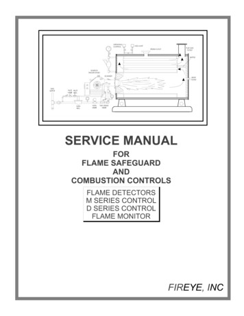
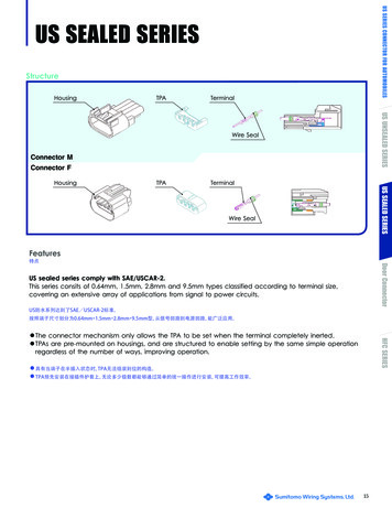
035-16328-002 Rev. C (0902)DUCT CONNECTORS318 4238SEECHART23814318 423814238238131211SEECHART2381312318 41143818 34438DUCT CONNECTOR DIMENSIONSDUCT CONNECTOR DIMENSIONSDUCT CONNECTORPART NUMBERDUCT CONNECTORDEPTHDUCT CONNECTORPART NUMBERDUCT 1/2”10-1/4”12-1/4”FIGURE 8 : Duct Connector DimensionsREAR WALLOF ENCLOSURE2-3/4MIN.CEILING CUT-OUTFOR ROOF JACK
direct vent forced air heating appliances for Manufactured Homes to be sold in the United States. 1. The return-air opening into the closet, regardless of loca-tion, is to be sized not less than specified on the appli-ance's rating plate. 2. If the return-