Transcription
Instruction ManualTR200Literature Order NumberDateSupersedeswww.trane.comFor more information, contact your local Traneoffice or e-mail us at comfort@trane.comBAS-SVX19C-ENMarch 2010August 2009Trane has a policy of continuous product and product data improvement and reserves theright to change design and specifications without notice.BAS-SVX19C-ENMarch 2010130R0447MG12H322*MG12H322*Rev. 2010-03-12BAS-SVX19C-EN
Table of ContentsSafety1-1High Voltage Warning1-2Before Commencing Repair Work1-4Special Conditions1-4IT Mains1-4Introduction2-1Mechanical Installation3-1Before Starting3-1How to Install3-2Mechanical DimensionsElectrical InstallationFuse Selection for Drives with Internal Drive FusingFuse Replacement TableHow to Connect3-34-14-14-44-4Electrical Installation and Control Cables4-6Mains Wiring Overview4-11Motor Wiring Overview4-20Motor Wiring Overview4-26DC Bus Connection4-27Relay Connection4-28How to Test Motor and Direction of Rotation4-33How to Operate the Frequency Converter5-1How to operate graphical keypad5-1Tips and Tricks5-11How to program the Frequency ConverterBAS-SVX19C-EN6-1-1
Quick Menu Mode6-1Function Set-ups6-12Parameter Lists TR200Default settings6-620-** Operation and Display6-631-** Load / Motor6-662-** Brakes6-683-** Reference / Ramps6-694-** Limits / Warnings6-715-** Digital In / Out6-726-** Analog In / Out6-748-** Communication and Options6-7611-** LonWorks6-7713-** Smart Logic Controller6-7814-** Special Functions6-7915-** Drive Information6-8116-** Data Readouts6-8318-** Info & Readouts6-8520-** Drive Closed Loop6-8621-** Ext. Closed Loop6-8822-** Application Functions6-9023-** Time Based Funtions6-9124-** Application Functions 26-9236-** Programmable I/O Option6-93Dedicated factory settingsTroubleshooting-26-626-957-1Alarms and Warnings7-1Fault Messages7-6BAS-SVX19C-EN
Acoustic Noise or VibrationSpecifications7-158-1General Specifications8-1Special Conditions8-11IndexBAS-SVX19C-EN9-1-3
-4BAS-SVX19C-EN
SafetyWarnings, Cautions and NoticesNote that warnings, cautions and notices appear at appropriate intervals throughout this manual. Warnings areprovide to alert installing contractors to potential hazards that could result in personal injury or death. Cautionsare designed to alert personnel to hazardous situations that could result in personal injury, while notices indicatea situation that could result in equipment or property-damage-only accidents.Your personal safety and the proper operation of this machine depend upon the strict observance of theseprecautions.Warnings, Cautions and Notices appear at appropriate sections throughout this literature. Read these carefully.Indicates a potentially hazardous situation which, if not avoided, could result in death or serious injury.Indicates a potentially hazardous situation which, if not avoided, could result in minor or moderate injury. It could alsobe used to alert against unsafe practices.NOTEIndicates a situation that could result in equipment or property-damage only accidents.NoteIndicates something important to be noted by the reader. Indicates default settingHazardous Voltage!Disconnect all electric power, including remote disconnects before servicing. Follow proper lockout/tagout proceduresto ensure the power can not be inadvertently energized. Failure to disconnect power before servicing could result indeath or serious injury.BAS-SVX19C-EN1-1
SafetyHigh Voltage WarningThe voltage of the frequency converter is dangerous whenever it is connected to mains. Incorrect installation of themotor or frequency converter could result indeath, serious injury or damage to the equipment. Consequently, it isessential to comply with the instructions in this manual as well as local and national rules and safety regulations.Safety NoteWARNINGFailure to follow instructions below could result in death or serious injury.Safety Regulations1. The frequency converter must be disconnected from mains if repair work is to be carried out. Check thatthe mains supply has been disconnected and that the necessary time has passed before removing motorand mains plugs.2.The [STOP/RESET] key on the keypad of the frequency converter does not disconnect the equipment frommains and is thus not to be used as a safety switch.3.Correct protective earthing of the equipment must be established, the user must be protected against supplyvoltage, and the motor must be protected against overload in accordance with applicable national and localregulations.4.The earth leakage currents are higher than 3.5 mA.5.Protection against motor overload is set by par. 1-90 Motor Thermal Protection. If this function is desired,set par. 1-90 Motor Thermal Protection to data value [ETR trip] (default value) or data value [ETR warning].Note: The function is initialized at 1.16 x rated motor current and rated motor frequency. For the NorthAmerican market: The ETR functions provide class 20 motor overload protection in accordance with NEC.6.Do not remove the plugs for the motor and mains supply while the frequency converter is connected tomains. Check that the mains supply has been disconnected and that the necessary time has passed beforeremoving motor and mains plugs.7.Please note that the frequency converter has more voltage inputs than L1, L2 and L3, when load sharing(linking of DC intermediate circuit) and external 24 Vdc have been installed. Check that all voltage inputshave been disconnected and that the necessary time has passed before commencing repair work.1-2BAS-SVX19C-EN
SafetyInstallation at high altitudes380 - 500 V, enclosure A, B and C: At altitudes above 2 km (6,561 ft), please contact Trane regarding PELV/Class II.380 - 500 V, enclosure D, E and F: At altitudes above 3 km (9,842 ft), please contact Trane regarding PELV/Class II.If the drive is to be installed over 2000m (6,561 ft) altitude, then the PELV specifications are not fulfilled anymore, i.e.the distances between components and critical parts become too small. To keep anyway the clearance for functionalinsulation, the risk for over-voltage must be reduced by means of external protective devices or kind of galvanic isolation.De-rating should also be taken into consideration, as cooling of the drive is not so effective at high altitude. Pleasecontact Trane in such cases.Failure to follow recommendations could result in death or serious injury.Warning against Unintended Start1.The motor can be brought to a stop by means of digital commands, bus commands, references or a local stop,while the frequency converter is connected to mains. If personal safety considerations make it necessary to ensurethat no unintended start occurs, these stop functions are not sufficient.2.While parameters are being changed, the motor may start. Consequently, the stop key [STOP/RESET] must alwaysbe activated; following which data can be modified.3.A motor that has been stopped may start if faults occur in the electronics of the frequency converter, or if atemporary overload or a fault in the supply mains or the motor connection ceases.Consequently, disconnect all electric power, including remote disconnects before servicing. Follow proper lockout/tagout procedures to ensure the power can not be inadvertently energized. Failure to follow recommendations couldresult in death or serious injury.Touching the electrical parts could result in death or serious injury - even after the equipment has been disconnectedfrom mains.Also make sure that other voltage inputs have been disconnected, such as external 24 Vdc, load sharing (linkageof DC intermediate circuit), as well as the motor connection for kinetic back up. Refer to the Operating Instructions for further safety guidelines.Failure to follow recommendations could result in death or serious injury.The frequency converter DC link capacitors remain charged after power has been disconnected. To avoid an electricalshock hazard, disconnect the frequency converter from the mains before carrying out maintenance. Wait at least asfollows before doing service on the frequency converter:Failure to follow recommendations could result in death or serious injury.Voltage (V)Min. Waiting Time (Minutes)15203040200 - 2405.5 - 45 kW380 - 48011 - 90 kW110 - 250 kW315 - 1000 kW525 - 60011 - 90 kW525 - 69011 - 90 kW45 - 400 kW450 - 1400 kWBe aware that there may be high voltage on the DC link even when the LEDs are turned off.41.1 - 3.7 kW1.1 - 7.5 kW1.1 - 7.5 kWBAS-SVX19C-EN1-3
SafetyBefore Commencing Repair WorkHazardous Voltage!1.Disconnect the frequency converter from mains2.Disconnect DC bus terminals 88 and 893.Wait at least the time mentioned in section General Warning above4.Remove motor cableFailure to follow recommendations could result in death or serious injury.Special ConditionsElectrical ratings:The rating indicated on the nameplate of the frequency converter is based on a typical 3-phase mains powersupply, within the specified voltage, current and temperature range, which is expected to be used in most applications.The frequency converters also support other special applications, which affect the electrical ratings of the frequency converter.Special conditions which affect the electrical ratings might be: Single phase applications High temperature applications which require de-rating of the electrical ratings Marine applications with more severe environmental conditions.Other applications might also affect the electrical ratings.Consult the relevant sections in this manual and in the TR200 Design Guide for information about the electricalratings.Installation requirements:The overall electrical safety of the frequency converter requires special installation considerations regarding: Fuses and circuit breakers for over-current and short-circuit protection Selection of power cables (mains, motor, brake, loadsharing and relay) Grid configuration (grounded delta transformer leg, IT,TN, etc.) Safety of low-voltage ports (PELV conditions).Consult the relevant clauses in these instructions and in the TR200 Design Guide for information about theinstallation requirements.IT MainsIT mainsDo not connect frequency converters with RFI-filters to mains supplies with a voltage between phase and earth ofmore than 440 V for 400 V converters and 760 V for 690 V converters.For 400 V IT mains and delta earth (grounded leg), mains voltage may exceed 440 V between phase and earth.For 690 V IT mains and delta earth (grounded leg), mains voltage may exceed 760 V between phase and earth.Failure to follow recommendations could result in death or serious injury.1-4BAS-SVX19C-EN
SafetyPar. 14-50 RFI Filter can be used to disconnect the internal RFI capacitors from the RFI filter to ground.BAS-SVX19C-EN1-5
SafetySoftware Version and Approvals: TR200TR200Software version:3.1xThis manual can be used with all TR200 frequency converters with software version 3.1xThe software version number can be seen from par. 15-43 Software Version.Disposal InstructionEquipment containing electrical components must not be disposed of togetherwith domestic waste.It must be separately collected with electrical and electronic waste according tolocal and currently valid legislation.1-6BAS-SVX19C-EN
IntroductionAvailable Literature for TR200-Operating Instructions provide the necessary information for getting the drive up and running.-Operating Instructions TR200 High Power-Design Guide entails all technical information about the drive and customer design and applications.-Programming Guide provides information on how to program and includes complete parameter descriptions.x Revision numberyy Language codeTrane technical literature is available in print from your local Trane Sales Office or online at:www.trane.com/vfdBAS-SVX19C-EN2-1
IntroductionAbbreviations and StandardsAbbreviations:aAWGAuto Tune CIILIMIT mainsJoule ican wire gaugeAutomatic Motor TuningCelsiusCurrentCurrent limitMains supply with star point in transformer floating to ground.EnergyFahrenheitFrequency ConverterFrequencyKilohertzLocal Control PanelMilliampereMillisecondMinuteControl ToolMotor Type DependentNewton MetresNominal motor currentNominal motor frequencyNominal motor powerNominal motor voltageParameterProtective Extra Low VoltagePowerPressureRated Inverter Output CurrentRevolutions Per MinuteSize RelatedTemperatureTimeTorque limitVoltageSI-units:m/s2I-P units:ft/s2AAmpJ N mft-lb, BtuHzkHzHzkHzin-lbsWPa N/m²Btu/hr, hppsi, psf, ft of waterCsFs,hrVVTable 2. 1: Abbreviation and standards table2-2BAS-SVX19C-EN
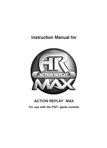
IntroductionFrequency Converter IdentificationBelow is an example of an identification label. This label is situated on the frequency converter and shows thetype and options fitted to the unit. See below for details of how to read the Type code string (T/C).Figure 2. 1: This example shows an identification label.Please have T/C (type code) number and serial number ready before contacting Trane.BAS-SVX19C-EN2-3
IntroductionType Code String low and medium powerTR 2 0DescriptionProduct group & FC SeriesPower ratingNumber of phasesPos1-68-1011Mains voltage11-12Enclosure13-15RFI filter16-17Brake18Display19Coating PCB20Mains option21Adaptation22AdaptationSoftware releaseSoftware language2324-2728A options29-30B options31-32C0 options MCOC1 optionsC option software33-343536-37D options38-39Possible choiceTR-2001.1- 1200 kW (P1K1 - P1M2)Three phases (T)T 2: 200-240 VACT 4: 380-480 VACE20: IP20E21: IP 21/NEMA Type 1E55: IP 55/NEMA Type 12E66: IP66P21: IP21/NEMA Type 1 w/backplateP55: IP55/NEMA Type 12 w/backplateH1: RFI filter class A1/BH2: RFI filter class A2H3: RFI filter class A1/B (reduced cable length)Hx: No RFI filterX: No brake chopper includedG: Graphical Local Control Panel (keypad)X: No Local Control PanelX. No coated PCBC: Coated PCBX: No Mains disconnect switch and Load Sharing1: With Mains disconnect switch (IP55 only)8: Mains
130R0447 MG12H322 Rev. 2010-03-12 *MG12H322* Instruction Manual March 2010 TR200 BAS-SVX19C-EN BAS-SVX19C-EN Trane has a policy of continuous