Transcription
Security Constrained Optimal Power Flow viaProximal Message PassingSambuddha Chakrabarti , Matt Kraning† , Eric Chu† , Ross Baldick and Stephen Boyd† Departmentof Electrical and Computer EngineeringThe University of Texas at Austin, Austin, Texas 78712–0240† Electrical Engineering DepartmentStanford University, Stanford, California 94305–9505power generation or consumption in any adverse (non-nominal)scenario. Transmission lines, which we model as two-terminaldevices, simply work according to the flow equations in anyscenario, except one in which they have failed. The goal is tominimize a composite cost function that includes the cost (andconstraints) of nominal operation, as well as those associatedwith operation in any of the (adverse) scenarios. This resultsin a large optimization problem, since each variable in thenetwork, namely, real power flow, is repeated N times, whereN is the number of contingencies. We use a suitable modifiedversion of the message passing algorithm in [11] to solve thisproblem efficiently. For simplicity, we consider only DC powerflows in this paper. The extension to AC power flow involvesapplying the AC-OPF model from [12], [13] to each scenarioand requiring that the phase angles of a given devices are equalacross all scenarios in the first time period. In this paper, weextend application of the Proximal Message Passing AlgorithmI. I NTRODUCTIONfrom solving the standard Optimal Power Flow(OPF) ProblemThe operation of power grids depends critically on the ability to solving the (N-1) Security Constrained OPF (SCOPF). Theto maintain economic efficiency in the presence of unforeseen rest of the paper is organized as follows: In section-II, weevents. In this paper, we consider the security-constrained give brief literature survey followed by section-III, where weoptimal power flow (SCOPF) problem, in which devices are derive the Mathematical Formulations for several differentconnected on a network and there exists a set of scenarios scenarios gradually increasing the level of complexity in our— each associated with a given probability of occurrence and model. Then, in Section-IV, the preceding generalized casescorresponding to the failure and/or degradation of a set of are reformulated into a different framework, DT N (Devicesdevices — over which we must ensure efficient operation of Terminals-Nets) Formulation, which is particularly suitable forthe network. For each scenario, the scenario objective is to the ADMM (Alternating Direction Method of Multipliers) [1]minimize the sum of the objective functions associated with Based Proximal Message Passing Algorithm to be applied to thethat scenario for each device. These objective functions extend problems. Thereafter, we derive the Proximal Message Passingover a given time horizon and encode operating costs and Algorithm for the scenarios focusing mainly on the Dynamicconstraints for a given device operating under that scenario. OPF (D-OPF) Problem in Section-V. Section-VI discusses someSolving the SCOPF generates a contingency plan for each of the numerical results. Finally, some concluding remarks aredevice in each scenario. The plans tell us the (real) power drawn and future works are mentioned in Section-VII.flow in each device under nominal system operation, asII. L ITERATURE S URVEY AND R ELATED W ORKwell as in a set of specified contingencies or scenarios. Thecontingencies can correspond to failure or degraded operationThe Optimal Power Flow Problem is at the heart of everyof a transmission line or generator, or they can correspond to kind of Power Systems planning and operations activities. Ita substantial change in a device. In each scenario the powers has been studied for more than half a century now. A recentfor each device must satisfy the network equations (taking reference that provides a good summary of the historicalinto account any failures for that scenario). These powers are development of the problem is [2] by Cain, O’Neill and Castillo.constrained in various ways across the scenarios. Generators The references cited there also provides good insights intoand loads, for example, might be constrained to maintain their formulation and modeling particularly, of the ACOPF. TheAbstract—In this paper, we propose a distributed algorithmto solve the Security Constrained Optimal Power Flow (SCOPF) Problem. We consider a network of devices, each withits own dynamic constraints and objective, subject to reliabilityconstraints across multiple scenarios. Each scenario correspondsto the failure or degradation of a set of devices and has anassociated probability of occurrence. The network objective isto minimize the cost of operation of all devices, over a giventime horizon, across all scenarios subject to the constraints oftransmission limit, upper and lower generating limits, generationload balance etc. This is a large optimization problem, withvariables for consumption and generation for each device, in eachscenario. In this paper, we extend the proximal message passingframework to handle reliability constraints across scenarios. Theresulting algorithm is extremely scalable with respect to bothnetwork size and the number of scenarios.Index Terms—Alternating Direction Method of Multipliers(ADMM), Locational Marginal Price (LMP), Augmented Lagrangian, Shift Factor Matrix978-1-4799-3960-2/14/ 31.00 c 2014 IEEE
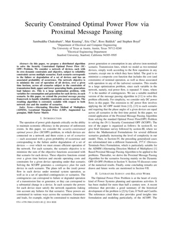
pioneering work on the Security Constrained OPF (SCOPF) wasdone by Stott et al in [14]. Significant early works on ADMMmethod during the 70s and 80s were [8], [6], [5] etc. followedby work during the 90’s which include [4], [3]. Combiningthese two fields gives rise to the Distributed Computationalmethods for OPF problem and significant references in thatfield include works by Baldick and Kim [9], [10]. Particularly,the last reference provides a good comparison of the distributedmethods till the end of 90s.Fig. 1: Three transmission lines, a,Pn2b, c, joining two- demand buses, 1, and 2.D21Pn12demandD1a, b, c: capacity 100 MW/125 MWB. Illustration of Simplest Two Bus CaseIII. C ONVENTIONAL OPF F ORMULATIONSIn this section, we consider the conventional or traditionalOPF Formulation. We will next introduce the notations andconventions we are going to use for the rest of the paper.First consider the simplest possible case of a two bus systemshown in Fig. 1. There are three transmission lines betweenthe two buses with equal impedances and equal power carryingcapabilities (100 MW: Continuous and 125 MW: Short time).A. Notations and ConventionsAssume,that the marginal costs for generating power areWe have categorized the entities used in the subsequent 10/MWhand 20/MWh for Generators 1 and 2 respectivelyformulations into four different groups: Sets, Elements, Indexandtheystaythe same for the entire range of generatingand Parameters.capability.Wewilltry to solve a very simple (N-1) Security1) Sets: D: Set of Devicesconstraineddispatchcalculation for such a system. We willT : Set of Terminalsbuildthemodelinsteps,increasing the complexity and addingN : Set of Nets or Buseson new constraints for making the analysis more realistic atThe next three sets form partitions of the set of devices:each step. We will generalize the analysis to arbitrary systemsG D: Set of Generatorsat each step. This approach will help us gain insight as to whatT D: Set of Transmission Linesexactly is going on physically, as well as understand how theL D: Set of LoadsL {0, 1, 2, ., L }: Set of possible (N-1) Contingencies. The mathematical model is fitting into the pertinent situation. Firstassume that it is certain that no line outages are ever going toelement, 0 indicates the base case.happen and so we can transfer a maximum of 300 MW from2) Elements: t: Elements of TBus-1 to Bus-2. Let load D2 and D1 be 500 MW and 300 MW,g: Elements of Grespectively, and also let both the generators have very high orD: Elements of Linfinite generating capability. So, Generator-1 will be generatingT : Elements of TP1 D1 300 600M W , Generator-2 will be generatingN : Elements of N3) Indices: i, j, k: Buses, c: Contingencies, q: Generators, the remaining 500-300 i.e. 200 MW, and the LMPs (LMP:k: Terminals, d: Loads, r: Transmission Lines (in this section, Locational Marginal Prices for electricity, the incremental costfor generating or providing power at a particular bus, the pricewe index them using the bus indices of the ends).4) Parameters: Rij , Xij , Bij , Zij Rij jXij : Resistance, at which electricity is traded in the wholesale market) at busesReactance, Susceptance and Impedance of the transmission line 1 and 2 will be 10/MWh and 20/MWh, respectively. Thebetween buses i and j (for this section) and RTr , XTr , ZTr problem for this system can be mathematically formulated asRTr jXTr : Resistance, Reactance and Impedance of the rth follows, solving which will actually give the same results thatwe just intuitively examined.Transmission Line (for the next section)The variables are the real power P and the bus angles (There are no bus angles for DC tie-lines). The following is the convention we follow in order to identifymin C1 (P1 ) C2 (P2 )(1a)the associations of any particular variable to the sets:P1 ject to : P P D D(1b)(c)1TerminalNumberFor instance, PNi t indicates the real power flowing out of thekk th terminal, which belongs to the ith net, for the contingency(c)scenario, (c). PTr t indicates the real power flowing out ofkthe k th terminal, which belongs to the rth Transmission Line(Device), for the contingency scenario, (c).In the example in Fig. 1, the terminals of generators 1 and 2 arerespectively t1 and t5 . The terminals of the three transmissionlines on Bus-1, which is also net N1 are t2(I,II,III) and thoseat Bus-2, which is also net N2 are t4(I,II,III) , whereas thoseof loads D1 and D2 are t3 and t6 respectively. P2 P12D1 L12D2 L Redundant Constraint(1c)(1d)where, P1 and P2 are real powers produced by Generators-1and 2 respectively (Decision Variables) and L is the maximumpower transfer capability of the lines from Bus-1 to Bus-2,which is the sum total of all the three transmission lines betweenthe two buses.
C. Generalization of the Simplest Case to Multi-Bus Systemsmin C1 (P1 ) C2 (P2 )P1 ,P2The formulation is as follows:minPiXXi2N (P(2a)Ci (Pi )i2GSubject to :constraints)respectively). Now, the SCOPF is formulated as):Pi XDi(2b)i2ND) L(2c)where the bold face letters indicate vectors,is the ShiftFactor matrix. From now onward, we will use for the shiftfactor matrix and (c) for the shift factor matrix for a particularbase-case/contingency scenario. The index c 0 stands forbase-case. We can also think of as a T N matrix withelements ln which are the ratio between the real power flowon line l and the injection and withdrawal at bus n and theslack bus respectively, where the implicit assumption is that, thelinearization of line power flow holds true. Also, (P D) is thevector of the real power bus injections. Our next step would beto make the situation a little more realistic by considering themaximum and minimum real power generating limits and sothe only other constraints to be added in the above formulationsare Pi min Pi Pi max , 8i 2 N . (For those buses that donot have a Generator, Pi min Pi max 0).(3a)Subject to : P1 P2 D1 D2(3b)(P1 D1 )(X2 X3 ) a1Base Case :(X1 X2 X2 X3 X3 X1 )(3c)(P1 D1 )(X1 X3 ) a2(3d)(X1 X2 X2 X3 X3 X1 )(P1 D1 )(X1 X2 ) a3(3e)(X1 X2 X2 X3 X3 X1 )(P1 D1 )Outage of ”c” :(X2 ) a1(3f)(X1 X2 )(P1 D1 )(X1 ) a2(3g)(X1 X2 )(P1 D1 )Outage of ”b” :(X3 ) a1(3h)(X1 X3 )(P1 D1 )(X1 ) a3(3i)(X1 X3 )(P1 D1 )Outage of ”a” :(X3 ) a2(3j)(X3 X2 )(P1 D1 )(X2 ) a3(3k)(X3 X2 )It is to be observed that the particular case of equal lineimpedance and equal/unequal capacities can be derived fromthe above model.E. (N-1) Contingency Constrained OPF for the GeneralizedMulti-Bus Case: Unequal Capacities and Line ImpedancesD. (N-1) Contingency Constrained OPF for the Two Bus Case:Unequal Capacities and Line ImpedancesHence, the generalized SCOPF can be written down as:XminCi (Pi )(4a)Pii2GXXMoving on to the next level of sophistication in our model,Subject to :Pi Di(4b)we will now consider incorporation of (N1) securityi2Ni2Nconstraints in our formulation. In the simple two bus case(0) (0) (P D) L(4c)discussed previously, let’s, for the sake of simplicity, initially(c)ignore the short term ratings of lines. We are again assuming (c) (P D) L(4d)equal impedances of the lines and identical maximum line flowIV. DT N R EFORMULATIONS OF THE OPF S CENARIOSlimits of 100 MW for each line. In order to be secure withrespect to a single contingency, now only 200 MW can beIn this section we carry out the reformulation of only thetransferred from Bus-1 to Bus-2 and so, the remaining (500- generalized models that we presented in the last section in200) i.e. 300 MW of load has to be provided by Generator- order for us to be able to solve the problems by the Proximal2. Therefore, being secure with respect to the single outage Message Passing method. In the material that follows, we willof the line amounts to evaluating how much power can be group the terms of the objective into three different categories.transferred if the line is taken out of service, without violating We will define them for each case. These are:the limit constraints and actually allowing that very quantity 1)Cost of Generation (C(P )): This term consists of the actualof power to flow during pre-contingency. In a more general total cost of generating real power by the different generatorscontext, where the impedances as well as the capacities as well as the indicator functions corresponding to the lowerare different and lets assume that the impedances (in this and upper generating limits of the different generators. Forcase, the reactances, since we are neglecting the resistances) this term, the real power generated is always considered at theare X1 , X2 , X3 with X1X2X3 (with X1 , X2 , X3 base case.respectively, the reactances of lines 1, 2 and 3 with capacities 2)Line Flow Limit Constraint (F (P )): This term consistsa1 , a2 , a3 (with a1a2a3 , which ensures binding of the sum of the indicator functions corresponding to the
constraints meant for enforcement of the real power flow on 3)Power-AngleRelation:(P, ) Tr t Tr tP0kthe lines being less the maximum allowed, both at the base- Pk)Tr 2Ttk ,tk0 2Tr \T I (PTr tk X Trcase as well as different contingencies.With all the above components, the reformulated OPF for this3)Power-Angle Relation ( (P, )):This term consists of theparticular case can written as:sum of the indicator functions corresponding to the relationof the power flow at each end of the lines and the voltagemin C(P ) F (P ) (P, )(7a)Ptk , tkphase angles at the two ends, both at the base-case and theSubject to : P Ni tk 0, Ni tk 0, 8Ni 2 N , 8tk 2 Tcontingencies.(7b)A. DT N Formulation Applied to the Generalization of theB. DT N Formulation Applied to the (N-1) ContingencySimplest Case to Multi-Bus SystemsConstrainedGeneralized Multi-Bus Case: Unequal CapacitiesWe are considering here the generalization of the simplesttwo bus case to arbitrary systems and are going to reformulate and Unequal Line Impedancesthe OPF equations similar to the paradigm introduced in [11].The average net real power imbalance for the base case asLet us introduce the following sign convention that we will well as the contingencies are as follows (similar to the onesfollow throughout the rest of the paper: Power coming out of presented before in section 4.3):a terminal is positive and going into a terminal is consideredX1(c)(c)(c)P Ni PN i t P N i tnegative. Let Pti refer to the real power coming out of thekk Ni tk 2Ni \Tterminals ti each of which is associated with exactly one deviceand one net. Since the loads consume real power, in our two8Ni 2 N , 8tk 2 Ni \ T , 8(c) 2 L(8a)bus case, PD1 t3 D1 , PD2 t6 D2 . Let a particular net,Ni 2 N has Ni number of terminals. The average power and the phase consistency constraints for the base case as wellas contingencies are as follows:mismatch for each net is as follows:XX1(c)(c)1 Ni Ni t(9a)P Ni PN i t k P N i t kk N i Ni tk 2Ni \Ttk 2Ni \T8Ni 2 N , 8tk 2 Ni \ T(5a)kSimilarly, the phase angle inconsistency equations are: Ni 1 Ni X N i tk(6a)(6b)(9b)The components of the objective function are as follows:1)Cost of Generation(At Base Case):P G (0)C(P (0) ) tk 2gq \T ,q 1 (Cgq (Pgq t ) (0) Ni8Ni 2 N , 8tk 2 Ni \ T(c) Nik8Ni 2 N , 8tk 2 Ni \ T , 8(c) 2 Ltk 2Ni \T Ni tk Ni tk(c)(c) Ni t Ni t(0)kI (Pmaxgq Pgq t ) I (Pgq tPmingq ))kk2)Line Flow Limit Constraint ((N-1) Secure):PPP(c)(c)F (P (c) ) (c)2L Tr 2T tk 2Tr \T I (LTr PTr t )k3)Power-Angle Relation((N-1)Secure):PPP(c)(P (c) , (c) ) (c)2LTr 2Ttk ,t 0 2Tr \T I (PTr t The indicator functions correspondingPP to the line flow limitconstraints are as follows: Tr 2T tk 2Tr \T I (LmaxTrkk PTr tk ).(where I (x) 0 if x0 and 1(c)(c) T r Trtkt 0otherwise) The indicator functions corresponding tok)(c)X Trthe defining relationship between the power injectionson the lines and the phase angles are as follows: So, the reformulated OPF Problem for this case is as follows: Tr t Tr tPP0kkmin C(P (0) ) F (P (c) ) (P (c) , (c) )(10a) ).(which,Tr 2Ttk ,tk0 2Tr \T I (PTr tkX Tr(c) (c)Pt , tkkunlike the previously defined indicator functions are zero only(c)(c)when the respective arguments are zero and 1 otherwise)Subject to : P Ni t 0, Ni t 0, 8Ni 2 N , 8tk 2 T ,kkThe indicator functions corresponding to the Generator8(c)2L(10b)maximum and minimum real power generating limits areXXP G (c)(0)Pgq t ) I (Pgq tPmingq ))PN i T PNi T , 8(c) 2 L, 8Ni 2 Ntk 2gq \T ,q 1 (I (Pmaxgqkkr tkr tkand the Generator Cost functions are of the formTr 2Ni \TTr 2Ni \T2(10c)Cgq (Pgq t ) gq Pgq t gq Pgq t gq . As before,kkkthe different terms of the objective function in this case are:The last constraint is for enforcing the condition that within aP G 1)Cost of Generation: C(P ) tk 2gq \T ,q 1 (Cgq (Pgq t ) particular dispatch interval, the pre-and post-contingency buskI (Pmaxgq Pgq t ) injections for the transmission lines are the same and the onlykI (Pgq tPmingq ))things that change are the line flows, as long as we considerkoutage of only transmission elements and are in the DC-OPF2)LineFlowLimitConstraint:F(P) PPregime.I(L P )maxTrT r tkTr 2Ttk 2Tr \T
V. ADMM BASED P ROXIMAL M ESSAGE PASSINGA LGORITHM FOR THE SCOPF P ROBLEMIn this section, we will present the ADMM Based ProximalMessage Passing iterations for only two of the models presentedin the previous sections: The Generalization to the Multi-BusCase with and without the (N-1) Contingency Constraint. Forthe sake of completeness, we present here a brief summaryof the ADMM based Proximal Message Passing Algorithm asapplied to OPF problem, but for details we refer the readersto [11] and [1].A. Message passing algorithmIn this section, we describe the message passing algorithmused to solve the SC-OPF. We begin by assuming that all deviceobjective functions are convex, closed, and proper (CCP) functions. We then derive a distributed, message passing algorithmusing operator splitting and the alternating directions methodof multipliers (ADMM) [1]. This algorithm has guaranteedconvergence for CCP functions, is fully decentralized, and isrobust.B. Consensus form SC-OPFBefore applying ADMM to solve the SC-OPF, we firstreplicate the power plans P 2 R T ( L 1) by introducinga copy, z 2 R T ( L 1) , of the plans. We then solve theconsensus form SC-OPF:minimize f (P )subject to z̄ 0P z.Lagrangian by completing the squares. ADMM is then P ( 1) argmin f (P ) ( /2)kP z ( ) u( ) k22P ( 1)z argmin g(z) ( /2)kP ( 1) z u( ) k22u( 1) uz( )z ( 1) ).where the superscript is an iteration counter. Because of ourproblem structure, we can further simplify ADMM. The P updates separate across devices and ( 1)( )( )Pd argmin fd (Pd ) ( /2)kPd zd ud k22Pdfor all d 2 D. Furthermore, the z-updates separate across netsand zNi -update is just a Euclidean projection on to the setz̄Ni 0 and can be solved analytically, so( 1)zN i ( 1)PN i( )( 1) uNiP̄Ni( )ūNi .Substituting this expression for zNi in to the u-update—whichalso splits across nets—we obtain the proximal messagepassing algorithm:1) Proximal plan updates.( 1)Pd ( )proxfd , (Pd( )P̄d( )ud ),8d 2 D.2) Scaled price updates.( 1)(11) (P ( 1)uNi: ( )( 1)uNi P̄Ni,8Ni 2 N ,where the proximal function for a function g is given byWhere z̄ is the arithmetic mean of z associated with a particularproxg, (v) argmin(g(x) ( /2)kx vk22 ).xnet. Because of the consensus constraint, when we solve theconsensus form SC-OPF, the optimal solution will agree with This algorithm alternates between evaluating prox functionsthe solution of the original SC-OPF. We introduce the indicator (in parallel) on each device and performing price updates onfunction g(z) I{z z̄ 0} (z), which is 0 whenever z̄ 0 and each net. This algorithm has the following three properties: 1 otherwise (if the power balance constraint is violated).a) Convergence.: With mild conditions on device objecBecause z̄ is the averageT power at each net, the set {z z̄ 0} tive functions fd —namely, that they are closed, convex, andcan be written as Ni 2N {z z̄Ni 0}, where z̄Ni is the proper—and provided a feasible solution exists, the followingaverage power at net Ni ; then,properties of our algorithm hold.XX1) Residual convergence. P̄ ( ) ! 0 as ! 1,I{z z̄Ni 0} (z).g(z) gNi (z) P( )2) Objectiveconvergence. Ni 2NNi 2Nd2D fd (Pd )P( )?Ni 2N gNi (PNi ) ! f as ! 1,Since the summands in the last expression only involve each3)Dualvariable convergence. u( ) y ( ) ! y ? as !net Ni separately, g(z) separates across nets completely1,Xg(z) I{zNi z̄Ni 0} (zNi ).where f ? is the optimal value for the (convex) SC-OPF, andNi 2Ny ? are the optimal dual variables (prices). A proof of theseconditions can be found in [1]. Convergence of our algorithmC. ADMM and the prox-project message passing algorithmguarantees that, if message passing is run long enough, powerWe apply ADMM to solve the SC-OPF by first forming the balance will be satisfied by P ( ) to any desired accuracy.(scaled) augmented Lagrangian,b) Distributed.: As long as each device has the ability toaccess the average power imbalance for the nets it shares withL(P, z, u) f (P ) g(z) ( /2)kP z uk22 ,its neighbors, this algorithm can be completely decentralized.where u (1/ )y is the scaled dual variable y associated with Then, the algorithm consists of each device planning for eachthe consensus constraint P z. We obtained the augmented contingency and a broadcast of plans to its neighbors.
D. Stopping criterionWe can define primal and dual residuals for the prox-projectmessage passing algorithm:r( ) P̄( ),s( ) (P( )P̄( ))(P( 1)P̄( 1) ) .Here P ( ) is interpreted as a power plan. A simple terminatingcriterion for prox-project message passing is whenkr( ) k2 pri ,1) Iterates for Generators: They consist of the updateequations for the real power and voltage-phase angles of thegenerator terminals and are as follows:( 1)( 1)(Pgq tk , gq tk ) argminPgq tk, gq tk [Cgq tk (Pgq tk , gq tk ) I (Pmaxgq Pgq t ) I (Pgq tPmingq ) kk2 ( )( )( )( ) 2( Pgq tzgq tk ugq tk gq t gq tk vgq tk )],kk2228gq 2 G, tk 2 T \ G(13a)ks( ) k2 dual ,Here, , ( )(utk ) and ( )(vtk ) are the iteration count, dualvariable for power balance and dual variable for phase consiswhere pri and dual are, respectively, primal and dual toler- tency constraints respectively. is the penalty parameter of theances.Augmented Lagrangian term.2) Iterates for Transmission Lines: They consist of theupdateequations for the real power and voltage-phase anglesE. Choice of of the Transmission Line terminals, which are two terminalThe value of the algorithm parameter can greatly affect devices and are as follows:the convergence rate of the message passing algorithm. There( 1) ( 1)(PTr tk , Tr tk )are no known methods for choosing the optimal value of aXpriori, except in certain special cases [7]. For more details on argminPTr t , Tr t [(LTr PTr tk kk selection, consult [1].0k,k 2T \TrF. Implementation of proximal functionsI (PTr tk Each device is responsible for implementing its proximalfunction. In general, evaluating the proximal function requiressolving an optimization problem. The complexity of solvingthis optimization problem depends on the structure of the localproblem. In the case of SC-OPF, the variables are the localpower plans Pd and any other private variables. At most, the(0)variables are coupled through the base case Pd . This results inan arrow structure in the KKT system of the local optimizationproblem. This kind of structure can be exploited and solvedwith linear complexity. If the power plans do not couple throughthe base case, then the local problem is completely separableacross the contingencies. Because of this simple structure inthe local SC-OPF problems on each device, we can quicklyand efficiently evaluate the proximal functions for each device.G. Proximal Message Passing for Generalization of the Simplest Case to Multi-Bus SystemsA slightly reformulated version of the DT N equations fromthe last section, which allows us to apply the Proximal MessagePassing Algorithm is presented here:min C(P ) F (P ) (P, ) Ptk , tkXNi 2N N t ))(I(zNi tk ) I( i k(12a)Subject to : Ptk ztk , tk tk , 8Ni 2 N , 8tk 2 T(12b) N t ) are indicator functions of the setswhere I(zNi tk ) and I( i k{ztk z Ni tk } and { tk Ni tk } respectively. ( PTr tk2( )( ) T r tk Tr tk0XTr2zTr tk uTr tk Tr tk2) ( )( )2 Tr tk vTr tk ))],2(14a)8Tr 2 T, tk 2 T \ T3) Iterates for Loads: They consist of the update equationsfor the real power and voltage-phase angles of the loads (whichhave constant real power consumption) and are as follows:( 1)( 1) Dd t k( )P D d t k PD d t k2 ( )( ) argmin D t [ ( Dd tk Dd tk vDd tk )],d k 228Dd 2 L, tk 2 T \ L(15a)4) Iterates for Nets: We are writing here just the analyticalforms already derived in [11].( 1)zN i t k8Ni 2 N , 8tk 2 T \ Ni( )uN i tk( 1)( )( 1)P N i tk(16a)( 1)( 1)( ) N i t k v N i tk N i t k( 1)( )( 1)( 1)uNi tk uNi tk (PNi tkzN i t k )( 1)( )( 1)( 1)vNi tk vNi tk ( Ni tk N i tk )(16b) PN i t ku N i tk(16c)(16d)In the above, all the devices update their variables in parallel.Then all the nets update the first two variables in parallel andthen update the next two in parallel. It is to be observed herethat, each PNi tk actually comes from the updates from thedevices in the previous set of updates, because each of themis actually the real power output/consumption of the respectivedevice having the same terminal in the particular net. Using the
above equations, the prox-functions and the proximal messagepassing algorithm for this case can be written as follows:( 1)2) Iterates for Transmission Lines:( 1)(Pgq tk , gq tk ) ( )P gq t k( )proxC(P ), (Pgq tk( 1)( 1)( 1) prox( )P T r tk( ), (PTr tk ( ) gq t k( )vgq tk ),(17a)8gq 2 G(PTr tk , Tr tk , PTr t proxF (c)( 1)( )( 1)u gq tk , v gq tkk0(PTr tk argminP (c)(c)Tr tk , Tr tk( 1), T r t 0 )( )(c)( 1), T r t k( 1)[( ) T r tk8Tr 2 T( 1) ( 1)(PDd tk , Dd tk )( )( 1)( )vDd tk ), 8Dd 2D, (v Dd tk Dd tk( 1)( 1)( )uNi tk uNi tk P Ni tk , 8Ni 2 N(c)I (PTr tk( )vTr tk ),(17b)L( 1)( )( 1)vNi tk ṽNi tk Ni tk , 8Ni 2 N (c)( PTr tk2(c)( 1)kk,k0 2T \Tr(c)kuT r tk , v T r tk (c)( 1), PTr t 0 , Tr t 0 )kkX(c)(c)(I (LTr PTr t ) Tr t(c) Tr tkk0(c)XTr) (c)( ) 2(c)( )zTr tk uTr tk (c)( ) T r tk2(c)( ) 2vTr tk ))]2(17c)(c) Tr tk(17d)8Tr 2 T, tk 2 T \ T, (c) 2 L (20a)(17e)H. Proximal Message Passing for (N-1) Contingency Constrained Generalized Multi-Bus Case: Unequal Capacities andUnequal Line Impedances3) Iterates for Loads: They consist of the update equationsfor the real power and voltage-phase angles of the loads (whichhave constant real power consumption) and are as follows:The slightly reformulated DT N equations from previoussection are:(c)( 1)(c)( )PD d t kmin C(P (0) ) F (P (c) ) (P (c) , (c) )(c)( 1) Dd t k(c) (c), tkkPtX X (c)2L Ni 2N(c)(c)(c) (I(zNi tk ) I( Ni tk ))(c)(c)(18a) PDd tk Ddtk (c)(c)( )(c)( ) 2 Dd tk vDd tk )], argmin (c) [ ( Dd tkDd tk 228Dd 2 L, tk 2 T \ L, (c) 2 L(21a)(c)Subject to : Ptk ztk , tk tk , 8Ni 2 N , 8tk 2 T ,(18b)8(c) 2 LIt is to be observed here that the power balance and thephase consistency constraints need to be satisfied for eachand every contingency scenario. The different update equationsof the Proximal Message Passing Algorithm in this case areas follows:1) Iterates for Generators: They consist of the updateequations for the real power output and voltage-phase angles ofthe generator terminals for both the base case and the different(N-1) contingency scenarios and are as follows:(0)( 1) (c)( 1)(Pgq tk, g q t k) argminP (0)(c)gq tk , gq tk(c)2L(c)( )k(c)( ) 2 gq tk vgq tk )],8gq 2 G, tk 2 T \ G(c)( 1)zN i t k8Ni 2 N , 8tk 2 T \ Ni , 8(c) 2 L(c)( )(c)( 1)(c)( )(c)( 1)P N i tk(22a)(c)( 1)(c)( 1)(c)( ) N i tk v N i tk N i tk(c)( 1)(c)( )(c)( 1)(c)( 1)u N i tk uNi tk (PNi tkzN i t k)(c)( 1)(c)( )(c)( 1)(c)( 1)v N i tk vNi tk ( Ni tk N i tk)(22b) u N i t k PN i t kuN i tk(22c)(22d)(0)(c)[Cgq tk (Pgq tk , gq tk ) I (PgmaxPg(0)) I (Pg(0)Pgmin) qqtqtqkkX (c)( )(c)( ) 2( )( Pg(0)zgq tk ugq tk qtk22 g(c)qt4) Iterates for Nets: We are writing here just the analyticalforms already derived in [11].2(19a)In the above, as before, not only do all the d
OPF (D-OPF) Problem in Section-V. Section-VI discusses some of the numerical results. Finally, some concluding remarks are drawn and future works are mentioned in Section-VII. II. LITERATURESURVEY ANDRELATEDWORK The Optimal Power Flow Problem is at the heart of every kind of Power Systems planning and operations activities. It