Transcription
PLAY IT SAFE!OPERATION, MAINTENANCEAND INSTALLATION MANUALFORVERTICAL RECYCLER BALERINCLUDING THESE -6030LPV-6042LPINDUSTRIES COMPANYVERNON, AL - YERINGTON, NV - CLEARFIELD, PALEEDS, AL - FAYETTE, ALMarathon Equipment Co. OMI Manual No. 0003, Rev. 01/01
CONTENTSSECTION 1 - OperationIntroduction . 1-1Pre-Operating Instructions . 1-2ControlsFor HD and V-6030LP Units . 1-3For V-6030 and V-4830 Units . 1-4For V6042LP Units . 1-5Control Description . 1-6Operating InstructionsMaking A Bale - HD and LP Units . 1-7Making a Bale - V-6030 and V-4830 . 1-8Bale Tie Off - V-6030HD, V-4830HD, V-7230HD 1-9Diagram . 1-10Bale Tie Off - V-6030LP . 1-11Diagram . 1-12Bale Tie Off - V-6042LP . 1-13Diagram . 1-14Bale Tie Off - V-4830 and V-6030 . 1-15Diagram . 1-16Tie Slot Cleaning-Diagram . 1-17Decals . 1-18Decal Placement For Vertical Balers . 1-20SECTION 2 - MaintenanceLock-Out & Tag-Out Instructions . 2-1Supporting of Platen . 2-2Periodic Maintenance . 2-3ProceduresPressure Setting . 2-4Interlock Testing . 2-4Cylinder Removal . 2-5Cylinder Rebuilding . 2-6Limit Switch Adjustment . 2-6Warranty and Service on Motors . 2-6Feed Gate Latch Adjustment . 2-7Principles of Operation . 2-8Baler Specifications. 2-10Timer Adjustment . 2-11Charts . 2-12Parts List . 2-13Panel BoxFor HD and LP Units . 2-14For V-6030 and V-4830 Units . 2-15
CONTENTSSECTION 2 - Maintenance (continued)Power UnitFor 4830, 6030, 4830HD, 6030HD, & 7230HD . 2-16For 6030LP . 2-17For 6042LP . 2-18Hydraulic SchematicFor Vertical Balers - Typical . 2-19For V6042LP . 2-20Trouble-Shooting Chart .2-21SECTION 3 - InstallationOff-Loading and Up-Ending Of Baler .General Installation .Electrical Installation .Start-Up Instructions .Copyright Marathon Equipment Company, January 2001.3-13-23-33-4
1 OPERATIONINTRODUCTIONTHANK YOU FOR PURCHASING A MARATHON VERTICAL BALER.This product is designed to give you reliable service and superior performance for yearsto come. To guarantee top performance and the safest operation of the baler, each person involved in the operation, maintenance and installation of the baler should read andthoroughly understand the instructions in this manual and follow all warnings.The employer(s) involved in the operation, maintenance and installation of the balershould read and understand the most current version of the following applicable standards:ANSI Standard No. Z245.5, “Safety Requirements For Baling Equipment”(A copy of this standard may be obtained from Marathon EquipmentCompany, Field Service Department, at 1-800-633-8974).OSHA 29 CFR, Part 1910.147, “The control of hazardous energy (lockout/tagout)”ALL SERVICE OR REPAIR PROCEDURES DESCRIBED IN THISMANUAL SHOULD BE PERFORMED BY AUTHORIZED, FULLYTRAINED PERSONNEL.Any service or repairs that go beyond the scope of this manualshould be performed by factory authorized personnel only.IF YOU SHOULD NEED FURTHER ASSISTANCE, PLEASE CONTACT YOURDISTRIBUTOR. YOU WILL NEED TO PROVIDE THE BALER SERIALNUMBER, INSTALLATION DATE, AND ELECTRICAL SCHEMATIC NUMBERTO YOUR DISTRIBUTOR.IF YOU HAVE ANY SAFETY CONCERNS WITH THE EQUIPMENT, ORNEED FURTHER INFORMATION, PLEASE CONTACT US AT:Marathon Equipment CompanyP.O. Box 1798Vernon, Al 35592-1798Attn: Field Service Department1-800-633-89741-1
1 OPERATIONPRE-OPERATING INSTRUCTIONSSTAND CLEAR WHILEBALER IS IN OPERATION.WARNING: DO NOT OPERATE BALER UNTIL OPERATING INSTRUCTIONS ARETHOROUGHLY UNDERSTOOD.NEVER ENTER ANY PART OF THE BALER UNLESS THE DISCONNECTSWITCH HAS BEEN TURNED OFF AND PADLOCKED. Before starting thebaler, be sure no one is inside. Be certain that everyone is clear of all points ofoperation and pinch point areas before starting. See Lock-Out & Tag-Outinstructions in the Maintenance section.THE EMPLOYER SHOULD ALLOW ONLY AUTHORIZED AND TRAINED PERSONNEL TO OPERATETHIS BALER. This baler is equipped with a key operated locking system. The key(s) should be in the possession of only authorized personnel. Turn off andremove key after use.Federal regulation prohibits operation by persons under 18 years of age.BE CERTAIN TURNBUCKLE AND LATCH IS FULLY LOCKED IN PLACE ON BALECHAMBER DOOR BEFORE STARTING BALER.Pay close attention to the RED WARNING LIGHT on the control panel. If the lightis illuminated when the feed gate is raised, there is a malfunction of the magnetic interlock system. IN THIS EVENT, DISCONTINUE USE OF THE BALER ANDLOCK-OUT & TAG-OUT THE BALER PER THE INSTRUCTIONS IN THEMAINTENANCE SECTION, PAGE 2-1. Perform necessary repairs before continuing operation of the baler.ONLY AUTHORIZED PERSONNELSHOULD BE ALLOWED INSIDE THEPANEL BOX. The panel box containshigh voltage components. See Lock-Out& Tag-Out instructions in theMaintenance section.1-2
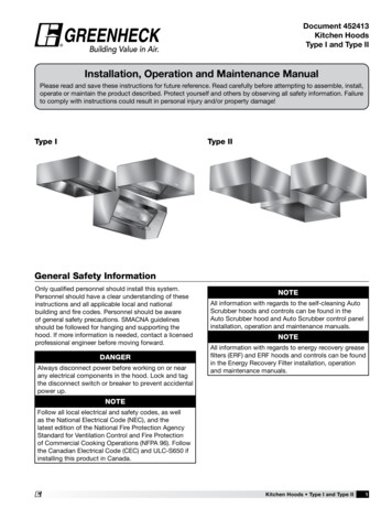
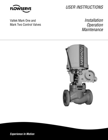
1 OPERATIONCONTROLS FOR V-4830HD, V-6030HD, V-6030LP, & V-7230HDNOTICEDISCONNECT SWITCHRED WARNING LIGHTWARNINGKEYED ON-OFF SWITCHAUTOCYCLE BUTTONEMERGENCY STOP BUTTONMOTOR OVERLOADRESET BUTTON(ON DOOR)MANUAL DOWN PUSHBUTTONMANUAL UP PUSHBUTTONBALE MADE LIGHTFEED GATECONTROL PANELPANEL BOXTURNBUCKLE TO BALECHAMBER DOOR LATCHBALE CHAMBER DOORFRONT VIEW - VERTICAL BALER1-3
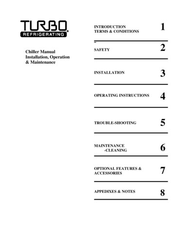
1 OPERATIONCONTROLS FOR V-6030 & V-4830RED WARNING LIGHTWARNINGKEYED ON-OFF SWITCHOFFAUTOCYCLE BUTTONONAUTO CYCLESTOPMANUAL UP BUTTONEMERGENCY STOPBUTTONMANUAL UPMANUAL DOWNMANUAL DOWN BUTTONMOTOR OVERLOADRESET BUTTON(ON DOOR)FEED GATENOTE: A fused disconnect is not provided on these models. The disconnectmust be provided, by the installer, perthe installation instructions in theInstallation section of this manual.CONTROL PANELPANEL BOXTURNBUCKLE TO BALECHAMBER DOOR LATCHBALE CHAMBER DOORFRONT VIEW - VERTICAL BALER1-4
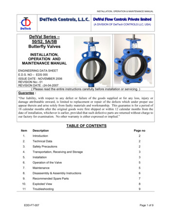
1 OPERATIONCONTROLS FOR V-6042LPRED WARNING LIGHTKEYED ON-OFF SWITCHDISCONNECTSWITCHAUTOCYCLE BUTTONEMERGENCY STOP BUTTONBALE MADE LIGHTMANUAL UP PUSHBUTTONMANUAL DOWN PUSHBUTTONRESET BUTTON(ON DOOR)RETRACT/EJECT SWITCHSIDE-MOUNTEDPOWER UNITCONTROL PANELPANEL BOXFEED GATETURNBUCKLE TO BALECHAMBER DOOR LATCHBALE CHAMBER DOORFRONT VIEW - LOW PROFILE VERTICAL BALER1-5
1 OPERATIONCONTROL DESCRIPTION1. ON-OFF (Keyed Selector Switch)Turning this switch to the ON position activates the other controls on the control station.The baler can not be operated unless the key is in the switch and the switch is in the ONposition. The purpose of this switch is to allow only authorized and trained personnel tooperate the baler. The key should be removed from the baler when not in use and shouldstay in the possession of only responsible and trained personnel.2. EMERGENCY STOP (Red Mushroom Head Pushbutton)Depressing this button will stop the machine at any point in the cycle.3. AUTOCYCLE (Green Pushbutton)The AUTOCYCLE button can be used only when the feed gate and bale door are closedand the keyswitch is in the ON position. Once depressed, the AUTOCYCLE button willcause the platen to move to the fully down position and back to the fully raised position(one complete cycle).4. MANUAL UP (Black Pushbutton)This button will only start the baler with the keyswitch in the ON position. Depressing thebutton will raise the platen with the feed gate and bale door opened or closed. It is normallyused during bale ejection. It can also be used to interrupt the automatic cycle and raise theplaten should it become necessary. The MANUAL UP button is a “Hold To Run” control,causing the baler to stop when it is released. WARNING: STAY CLEAR OF MOVINGPARTS WHEN USING THE MANUAL UP BUTTON WITH THE FEED GATE OPEN.5. MANUAL DOWN (Black Pushbutton)This button will only start the baler with the keyswitch in the ON position. Depressing thebutton will lower the platen only if the feed gate and bale door are closed. It can be used tointerrupt the automatic cycle and lower the platen should it become necessary. The MANUAL DOWN button is a “Hold To Run” control, causing the baler to stop when it is released.6. RED WARNING LIGHTThis light will warn the operator of a magnetic interlock switch malfunction. If the light is onand the feed gate is in the up position, there is a problem. Discontinue use of the baler.Turn off the baler and Lock-out and Tag-out per the instructions on page 2-1. Then call aqualified service person. The light SHOULD BE ON when the feed gate is in the down position.7. BALE MADE LIGHT (Not included on V-6030 and V-4830 models)This light will come on if enough material has been compacted to make a complete bale.8. RETRACT/EJECT (Spring-centered Switch) (USED ON THE V-6042LP ONLY)This spring-centered switch will eject the bale by means of a hydraulic ejector when theswitch is held to the EJECT position. When the button is held to the RETRACT position, theejector will retract. The MANUAL UP button must be depressed and held at the same timethe RETRACT/EJECT switch is used.1-6
1 OPERATIONOPERATING INSTRUCTIONS - MAKING A BALEWARNING: DO NOT OPERATE BALER UNTIL OPERATING INSTRUCTIONS AREUNDERSTOOD. See pages 1-3 through 1-5 for control panel layout and location.IN CASE OF EMERGENCY:Push the large red button toSTOPWARNING: Interlocks and safety devices were installed on this unit foryour protection. Never disable or bypass any interlock or safetydevice. Failure to comply with this warning could result in serious injury ordeath.TO MAKE A BALE : HD & LP Units1.Feed material into baler. If starting a new bale, place a large flat piece of material flat on the baler floor. NOTE: Do not attempt to overfill the feed chamber byforcing material into the chamber with the feed gate. This can cause gate releasemalfunction and may damage baler.2.Pull gate handle down to close feed gate. NOTE: Check red warning lightbefore closing feed gate. If gate is open and light is on, discontinue use of thebaler and call for service.3.To start the baler, insert the key into the keyswitch and turn to the ONposition.4.Press the AUTOCYCLE button. The platen will make a complete cycle downand back up. When the platen is in the full up position, the feed gate will automatically open and the motor will automatically shutdown.5.Repeat steps 1 through 4 until platen stops in down position and “BALE MADE”light comes on.NOTE: In normal operation, the feed gate will be open when you walk up toplace material into the baler. For added security, the feed gate can be manuallyclosed after the AUTOCYCLE(S). To open the gate, you will have to insert thekey into the keyswitch and run the baler through a complete AUTOCYCLE.1-7
1 OPERATIONOPERATING INSTRUCTIONS - MAKING A BALEWARNING: DO NOT OPERATE BALER UNTIL OPERATING INSTRUCTIONS AREUNDERSTOOD. See pages 1-3 through 1-5 for control panel layout and location.IN CASE OF EMERGENCY:Push the large red button toSTOPWARNING: Interlocks and safety devices were installed on this unit foryour protection. Never disable or bypass any interlock or safetydevice. Failure to comply with this warning could result in serious injury ordeath.TO MAKE A BALE : V-6030 & V-48301.Feed material into baler. If starting a new bale, place a large flat piece of material flat on the baler floor. NOTE: Do not attempt to overfill the feed chamber byforcing material into the chamber with the feed gate. This can cause gate releasemalfunction and may damage baler.2.Pull gate handle down to close feed gate. NOTE: Check red warning lightbefore closing feed gate. If gate is open and light is on, discontinue use of thebaler and call for service.3.To start the baler, insert the key into the keyswitch and turn to the ONposition.4.Press the AUTOCYCLE button. The platen will make a complete cycle downand back up. When the platen is in the full up position, the feed gate will automatically open and the motor will automatically shutdown.5.Repeat steps 1 through 4 until the arrow on the platen dwells in direct line withthe arrow on the NOTICE decal on the feed gate, before returning to the upposition.NOTE: In normal operation, the feed gate will be open when you walk up toplace material into the baler. For added security, the feed gate can be manuallyclosed after the AUTOCYCLE(S). To open the gate, you will have to insert thekey into the keyswitch and run the baler through a complete AUTOCYCLE.1-8
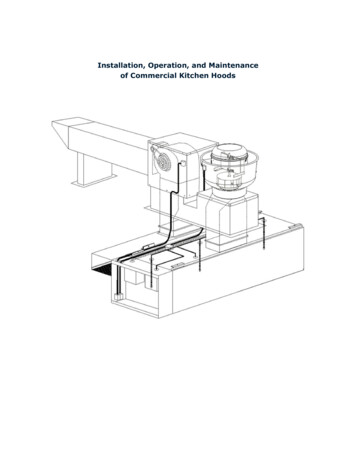
1 OPERATIONOPERATING INSTRUCTIONS BALE TIE OFF/BALE EJECT FOR V-6030HD, V-4830HD, V-7230HDWhen the BALE MADE light comes on, it is time to tie off the bale and eject the balefrom the baler. See page 1-3 for control panel layout and location. See the followingpage for a diagram of the following steps.FOR BALE TIE OFF & BALE EJECT (HD MODELS):1.Depress the MANUAL UP button until the feed gate opens.2.Insert a large, flat piece of material across the top of the bale.3.Close feed gate and depress the AUTOCYCLE button. The platenwill stop in the down position and the BALE MADE light will be illuminated.CAUTION: CLEAR ALL PERSONNEL FROM FRONT OF BALERBEFORE PROCEEDING WITH STEPS 4 THROUGH 8.4.Release the bale chamber door latch on the side of baler and openthe bale chamber door all the way. Feed gate is closed but will raisewhen the chamber door is opened.5.CAUTION: Wear safety glasses and leather gloves during the following operation:Tie off bale by inserting bale ties through the platen, “loop end” first.Always insert bale ties through the tie slots in the platen, first.Feed wire through until it comes out of the slot in the baler floor.Tie off each tie. Bale ties should be tightened only hand tight, allowing for bale expansion when released.6.Standing at the side, make sure all personnel are clear of the front ofthe baler. Depress the MANUAL UP button.7.Hold the MANUAL UP button until bale ejects, then release thebutton.8.Remove bale.9.Close and latch the bale chamber door. Close feed gate. DepressAUTOCYCLE to cycle and reset ejector. Bale sequence is ready tobe repeated.1-9
1 OPERATIONDIAGRAM BALE TIE OFF/BALE EJECT FOR V-6030HD, V-4830HD, V-7230HDSIDE VIEWFRONT VIEW OF BALERBALE TIE - INSERT AND PUSH THROUGHPLATEN GUIDES. TIES WILL CIRCLE THEBALE AND COME OUT OF THE FLOORGUIDES. SEE STEP 5.FEEDGATE CLOSED.STEP 3.PLATEN - BALE TIEGUIDE, 6 PLACES.SEE STEP 5.BALEMADELIGHTDOORLATCH OPENBALEBALE CHAMBERDOORFLOOR - BALE TIEGUIDE, 6 PLACES.SEE STEP 5.BALE TIE - TIGHTENEDHAND TIGHTBALE CHAMBER DOOR - OPEN.SEE STEP 4.SIDE VIEW- BALEBALE DURING EJECTIONBALEPALLET RECOMMENDEDFOR SUPPORTING BALESIDE VIEW1-10
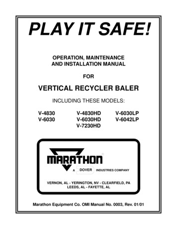
1 OPERATIONOPERATING INSTRUCTIONS BALE TIE OFF/BALE EJECT FOR V-6030LPWhen the BALE MADE light comes on, it is time to tie off the bale and eject the balefrom the baler. See page 1-3 for control panel layout and location. See the followingpage for a diagram of the following steps.FOR BALE TIE OFF & BALE EJECT (V-6030LP):1.Depress the MANUAL UP button until the feed gate opens.2.Insert a large, flat piece of material across the top of the bale.3.Close feed gate and depress the AUTOCYCLE button. The platenwill stop in the down position and the BALE MADE light will be illuminated.CAUTION: CLEAR ALL PERSONNEL FROM FRONT OF BALERBEFORE PROCEEDING WITH STEPS 4 THROUGH 8.Release the bale chamber door latch on the side of baler and openthe bale chamber door all the way. Feed gate is closed but will raisewhen the chamber door is opened.4.5.CAUTION: Wear safety glasses and leather gloves during the following operation:Facing the front of the bale, tie off bale by inserting bale ties (loopend first) through the platen. Always insert bale ties through thetie slots in the platen, first. Go to the rear of the baler and feedthe loop end of the bale ties down and through the aligned tie slots inthe floor. Finally, go to the front of the baler and tie each of theties. Bale ties should be tightened only hand tight, allowing for baleexpansion when released.6.Before ejecting the bale, go to the rear of the baler and manuallyengage the bale eject latch (WARNING: Never engage eject latch ifbale door is closed). To engage the latch, pull (rotate) the latch handle up all the way. Standing at the side, make sure all personnel areclear of the front of the baler. Depress the MANUAL UP button.7.Hold the MANUAL UP button until bale ejects, then release button.8.Remove bale.9.Close and latch bale chamber door. Close feed gate. Depress AUTOCYCLE to cycle and reset ejector. Bale sequence is ready to berepeated.1-11
1 OPERATIONDIAGRAM - BALE TIE OFF/BALE EJECT FOR V-6030LPFRONT VIEW OF BALERSIDE VIEWBALE TIE - INSERT AND PUSHTHROUGH PLATEN GUIDE.SEE STEP 5.FEEDGATE- CLOSED.STEP 3.BALE EJECT LATCHENGAGED. STEP 6.PLATEN - BALE TIEGUIDE, 6 PLACES.SEE STEP 5.BALEMADELIGHTFEED TIESTHROUGHFLOORGUIDES STEP 5.DOORLATCH OPENBALEFLOOR - BALE TIEGUIDE, 6 PLACES.SEE STEP 5.BALE CHAMBER DOOR OPEN.SEE STEP 4.BALE CHAMBERDOORBALE TIE - TIGHTENEDHAND TIGHTSIDE VIEW BALEBALE DURING EJECTION- STEP 7.BALEPALLET RECOMMENDED FORSUPPORTINGBALESIDE VIEW1-12
1 OPERATIONOPERATING INSTRUCTIONS BALE TIE OFF/BALE EJECT FOR V-6042LPWhen the BALE MADE light comes on, it is time to tie off the bale and eject the balefrom the baler. See page 1-5 for control panel layout and location. See the followingpage for a diagram of the following steps.FOR BALE TIE OFF & BALE EJECT (V-6042LP):1.Depress the MANUAL UP button until the feed gate opens.2.Insert a large, flat piece of material across the top of the bale.3.Close feed gate and depress the AUTOCYCLE button. The platenwill stop in the down position and the BALE MADE light will be illuminated.CAUTION: CLEAR ALL PERSONNEL FROM FRONT OF BALERBEFORE PROCEEDING WITH STEPS 4 THROUGH 8.4.Release the bale chamber door latch on the side of baler and openthe bale chamber door all the way. Feed gate is closed but will raisewhen chamber door is opened.5.CAUTION: Wear safety glasses and leather gloves during the following operation: Tie off bale by inserting bale ties through the platen,“loop end” first. Always insert bale ties through the tie slots in theplaten, first. Feed wire through until it comes out of the slot in thebaler floor. Tie off each tie. Bale ties should be tightened only handtight, allowing for bale expansion when platen is released.6.Depress the MANUAL UP button until the platen reaches its up position.7.
THANK YOU FOR PURCHASING A MARATHON VERTICAL BALER. This product is designed to give you reliable service and superior performance for years to come. To guarantee top performance and the safest operation of the baler, each per-son involved in the operation,