Transcription
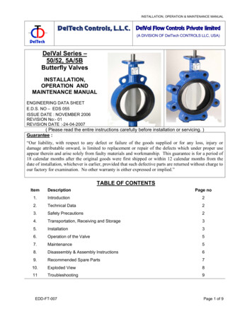
INSTALLATION, OPERATION & MAINTENANCE MANUALDelVal Flow Controls Private limited(A DIVISION OF DelTech CONTROLS LLC, USA)DelVal Series –50/52, 5A/5BButterfly ValvesINSTALLATION,OPERATION ANDMAINTENANCE MANUALENGINEERING DATA SHEETE.D.S. NO – EDS 055ISSUE DATE : NOVEMBER 2006REVISION No:- 01REVISION DATE :-24-04-2007( Please read the entire instructions carefully before installation or servicing. )Guarantee :“Our liability, with respect to any defect or failure of the goods supplied or for any loss, injury ordamage attributable onward, is limited to replacement or repair of the defects which under proper useappear therein and arise solely from faulty materials and workmanship. This guarantee is for a period of18 calendar months after the original goods were first shipped or within 12 calendar months from thedate of installation, whichever is earlier, provided that such defective parts are returned without charge toour factory for examination. No other warranty is either expressed or implied.”TABLE OF CONTENTSItemDescriptionPage no1.Introduction22.Technical Data23.Safety Precautions24.Transportation, Receiving and Storage35.Installation36.Operation of the Valve57.Maintenance58.Disassembly & Assembly Instructions69.Recommended Spare Parts710.Exploded View811Troubleshooting9EDD-FT-007Page 1 of 9
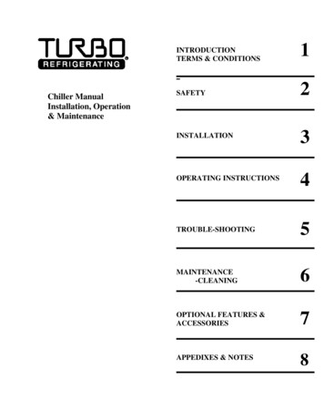
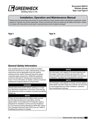
INSTALLATION, OPERATION & MAINTENANCE MANUAL1 Introduction3 Safety Precautions.1.1 Scope of the Manual.3.1 Do not exceed the valve pressure /temperature rating limitations!The purpose of this manual is to ensure that the valvessupplied are properly installed and maintained to givetrouble free performance. This manual covers DelVal single piece body butterflyvalves from 2” to 24” in both wafer and lug designs.1.2 Marking.Specifications of the valve are marked on the body or onname plate or both, prior to shipment. The identificationmarking generally consists of size of valve, pressurerating, body material, trim material and the date ofmanufacturing. ( Ref to fig 1.1 )Exceeding the pressure/temperature rating limitationsmarked on the valve may result in major damage orPersonal injury. Users of these valves should ensurethat the valve pressure / temperature is less than orequal to the rated pressure/temperatures. If ng/monitoring devices in the system for the safeoperation of the valve.3.2 Use the valve for specified application only! User to ensure that the valve is used only for thespecified application as agreed between themanufacturer and the purchaser.3.3 Follow the safety rules and regulations! DelValUser of the valve must be aware of all the safety rulesand regulations related to a particular environment inwhich the valve is to be used.3.4 Do not disassemble the valve or remove it fromthe pipeline while the valve is pressurized! Disassembling or removing a pressurized valve willresult in uncontrolled pressure release. Always isolatethe relevant part of the pipeline, release the pressurefrom the valve and remove the media beforedismantling the valve.Be aware of the type of media involved. Protect peopleand the environment from any harmful or poisonoussubstances.Make sure that no dust, dirt can enter the pipelineduring the valve maintenance.3.5 When handling the valve or the valve package,bear in mind its weight! Fig 1.1 Valve Marking2 Technical dataNever lift the valve or valve package by the handle, gearoperator, actuator or hand wheel. Place the ropesecurely around the valve body while handling thevalve. Refer to Fig No. 1.22.1 Pressure RatingConstruction :Single piece body both in wafer and lug design.Pressure Rating :Valve SizeRating2” - 12”175 PSI / 12 BAR.2” - 24”150 PSI / 10 BAR (PN10).2” – 24”50 PSI / 3.5 BAR.2” - 12”230 PSI / 16 BAR (PN 16).Seat Temperature Range.Seat typeTemperature RangeEPDM-130 F (-250 C) TO 2480 F (1200 C)BUNA-N / Nitrile-130 F (-250 C) TO 2120 F (1000 C)Viton / FKM-230 F (-50 C) TO 3920 F (2000 C)Silicone-580F (-500 C) TO 3560 F (1800 C)EDD-FT-007Fig 1.2 Lifting of the ValvePage 2 of 9
INSTALLATION, OPERATION & MAINTENANCE MANUAL4 Transportation, Receiving andStorage.4.1 Valves are being packed in cartons, boxes or palletswhile shipping to the customer. Care should betaken to store them in a suitable place. Werecommend storing the valves indoors in a dry anddust free atmosphere (Refer to figure 2.1). Whileunpacking the valves, check that the valves and anyother accessories have not been damaged duringtransportation.5 Installation5.1 When removing the valve from storage a careful checkshould be made to ensure that the valve has not beendamaged during the storage period.5.2 Valve open or close position is indicated on the notchplate for lever operated valves or on the top of the gearoperator for gear operator operated valves.5.3 Center valve, span body with bolts, but do not tighten.Slowly open disc to ensure that it clears adjacent pipeID and leave at full open position. Tighten bolts incris cross pattern refer fig 3.5.Fig 2.1 Storing the Valve. Caution:Placing the valves directly on the ground or on aconcrete floor should be avoided!4.2 All wrapping and protection on the valves should notbe removed until the valve is ready for installation.All valves are delivered with disc in 100 open position(Refer to figure 2.2).Fig 3.1 Lug Valve Installation.5.4 For flange welding center valve with disc 100 openbetween flanges, span bolts, align this assembly in pipeand tack weld flanges to pipe. After tack welding,remove valve and finish welding.W E L D IN GFig 2.2 Disc in 100 open position4.3 If the valves are stored for a long time, then all thevalves should be cleaned and hydro / pneumatictested before installation. Refer to GeneralArrangement drawing, which lists the appropriatetesting standards, or consult the nearest branchoffice / factory for more information.Fig 3.25.5 Valve should be checked for identification purpose andensure that characteristics of valve matches to thosespecified for piping specifications, for the line where thatis to be mounted. Nameplate instructions will give thenecessary information.4.4 Valves are bi-directional and can be installed ineither direction.4.5 Lever or hand wheel of gear operator for respectivevalves are packed loosely and kept in the same box,in which the valve is packed (wherever applicable).When handling the valve either by hand or bymechanical means, special care should be taken notto damage the lever or gear operator. Lift the valveonly as shown in fig 1.2. Lifting the valve from anyother location may damage the valve components.Fig 3.3 Valve Alignment.Note:It is recommended to use ASTM A193 Gr.B7 fasteners for flange bolting.EDD-FT-007Page 3 of 9
INSTALLATION, OPERATION & MAINTENANCE MANUALFig 3.4 : Installation of valve into pipe line.Note:a) Do not attempt to correct the line misalignment by means of flange bolting Ref to fig 3.3.b) Do not use flange gaskets Ref to fig 3.4.5.6 Recommended Bolt Tightening Sequence:Place the valve between the flanges, centre it and then span the valve body with all flange bolts, but do nottighten the bolts. Carefully open the disc to the full open position, making sure the disc does not hit theadjacent pipe I.D. Now systematically remove jack bolts or other flange spreaders, and hand-tighten the flangebolts as shown in fig.3.5 Very slowly close the valve disc to ensure disc edge clearance from adjacent pipeflange I.D. Now open the disc to full open and tighten all flanges bolts as per specification as shown in fig.Finally, repeat a full close to full open rotation of the disc to ensure proper clearance.Fig 3.5: Initial Centering & Flanging of ValveEDD-FT-007Page 4 of 9
INSTALLATION, OPERATION & MAINTENANCE MANUAL7 Maintenance.6 Operation of the Valve.6.1 For lever operated valves, the hand lever is eitherassembled with the valve or shipped loosedepending upon the size of valve / hand lever.6.2 For gear operated valves, THE GEAR OPERATOROPEN / CLOSE ADJUSTMENT HAS BEEN DONEPRIOR TO SHIPMENT AND MUST NOT BECHANGED. Rotation of hand wheel in the clockwisedirection closes the valve and counter clockwiserotation opens it. (Looking from hand wheel end) Thedetails of gear operator are shown in the fig. 4.1. Theinternal details/construction of gear operator mayvary as per manufacturers standard.Fig 4.1 : Details of gear operator.Note:Observe the safety precautions as outlined in section 3before performing maintenance.7.1 Preventive Maintenance.7.1.1In order to avoid valve failure during operation, allvalves in a process plant should be periodicallyinspected thoroughly to detect the wear of disc,seats, seals and even body. It is recommended thaton such occasions seats, seals and bushingsshould be replaced.7.1.2The type of process, fluids involved, workingconditions and location of the valves in the processplants, will determine the frequency of periodicinspection / maintenance which in fact will be madeat the time of partial or total shutdown of the plant.Preventive maintenance is absolutely essential asthe failure due to lack of the same may cause anemergency shut down of the plant.7.1.3Section 8 describes the procedure for disassembly,repair and assembly of the valve. The procedurewill be the same for a valve failing during operationdue to lack of preventive maintenance.7.1.4Once a valve is repaired, it should undergo acomplete set of tests to make sure that the valve isadequate for the original working conditions.Hydro/Pneumatic tests should be carried out as perthe specifications relevant to the valve (ReferGeneral Arrangement Drawing).6.3 DelTech Butterfly valve always close in a clockwisedirection. Valve should always be rotated through90º to the fully opened or fully closed position.6.4 Valve should be opened and closed slowly to avoidhammering effect on the valve and pipeline.6.5 Once the flushing is complete, valve should beoperated 3-4 times and then kept in the fully openposition.6.6 If the valve is not operating to fully open or fullyclosed position, and/or leaking, do not applyexcessive force to operate the valve. This candamage the seats or stem.Caution: Apply gradual force on the handwheel of the gearoperator and do not give impacts.Do not apply extra leverage (using pipe/bar), whenthe end stops of the gear operator are reached.EDD-FT-0077.2 Lubrication of Worm Gear operator.7.2.1Worm gear operators are packed with grease.Normally the grease is suitable for -20oC (-40F) to80oC (1760F). For other applications, consult thenearest branch office / factory.7.2.2Grease should be changed as following. If operatedfrequently, after approx. 3 years. If operated rarely,after approx. 5 years.7.2.3Recommended GreasesServogem EP2 (Extreme Pressure),Mobilux EP2,Valvoline EP2,Chevron EP2.Page 5 of 9
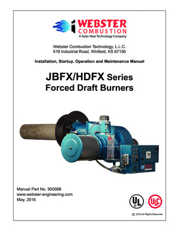
INSTALLATION, OPERATION & MAINTENANCE MANUAL!!WARNINGPipeline pressure can propel the loose flange bolts & flanges, and can cause personal injuryor equipment damage. Relieve pipeline pressure before removing flange bolts and flanges.WARNINGMoving Parts from accidental operation of powered (Pneumatically / Electrically) actuator cancause personal injury or equipment damage. Disconnect and lock power to actuator beforeservicing.8 Disassembly and AssemblyInstructions :8.1.3Remove the notch plate bolts (10,11,12) andremove the notch plate (9).8.1 Disassembly Instructions:( Refer to exploded view No. 10.1)8.1.4Remove the circlip (8) (fig 8.1) and pull the stem outwith stem retainer ring (7).8.1.5Pull the disc (3) from the body (1) as shown in fig8.28.1.6Remove the stem bushing (6) and U cup stem seal(5) from the body (4).8.1.7Compress the seat as shown and pull it out fromthe body (Refer to the fig 8.3).Before disassembling, please ensure that all spare partsas detailed in Table 1 of Section 9, are available. Forbelow mentioned procedure, the numbers in the bracketrefer to the part numbers of the components as indicatedin exploded view (fig no 10.1). In case the valve is in operation, release thepressure from the line.Rotate the valve stem (04) manually to keep theValve in the half-open position. This will removepressure in the pipeline.Always fully close valve before removing from line toavoid damage to discValve can be repaired by removing the entire valvefrom pipeline. Use mounting holes to lift the valve(Wherever applicable).8.1.18.1.2Note: After the complete disassembly of the valve, all thecomponents should be stored in a clean place to avoiddamage.8.2 Repair of Components.Unscrew the lever lock bolt (13). Lift the lever(14) by pressing the latch of the lever out of thestem (4) in case of hand lever operated valve.Lift the gear operator (15) out of the stem (4) byremoving the bolts in case of gear operatedvalve.8.2.1The metallic parts should be cleaned.8.2.2To clean the seats and seals use a dry clean cloth.8.2.3After cleaning components examine for damagedparts. Ensure that there are no scoring marks onthe metallic sealing surfaces. Check the seals forscratches / wear.8.2.4Replace the damaged parts. The parts such asseal, bushings are recommended to be replacedwith new ones whenever the valve is disassembled: refer to Table 1 of Section – 9 forfurther details.11Pull3C irclipP ress2P ull8Fig 8.1Fig 8.2Fig 8.3Disassembly of the Stem, Disc and Seat.Note: When the gear operator or hand lever or actuator is re-assembled on the valve, it may be necessary to adjustgear operator or hand lever or actuator travel stops to ensure proper setting of the butterfly in the open and closedposition8.3 Assembly Instructions.( Refer to exploded view No. 10.1)8.3.1VALVES OPERATING WITH LEVER.8.3.1.1 Place the body (1) on a clean work surface.8.3.1.2 Start assembly by pressing the seat as shown &pushing it into the valve body with seat stemholes aligned to the body stem holes as shownin the fig (8.4) and work the seat into the grooveprovided on the body.8.3.1.3 Position the disc (2) as shown in fig (8.5) takingcare that double D is at the bottom of the valvebody. Special care must be taken not
The purpose of this manual is to ensure that the valves supplied are properly installed and maintained to give trouble free performance. This manual covers DelVal single piece body butterfly valves from 2” to 24” in both wafer and lug designs. 1.2 Marking. Specifications of the valve are marked on the body or on