Transcription
Price: 50.00 US 75.00 CanadianWebster Combustion Technology, L.L.C.619 Industrial Road, Winfield, KS 67156Installation, Startup, Operation and Maintenance ManualJBFX/HDFX SeriesForced Draft BurnersManual Part No. 950088www.webster-engineering.comMay, 2016C 2016 All Rights Reserved
SAFETY PRECAUTIONSGood safety practices must be used when working on burner equipment. The potential energy in the electrical supply,fuel and related equipment must be handled with extreme care to prevent equipment failures, injuries and potentialdeath.Throughout this manual, the following symbols are used to identify potential problems.WARNINGThis indicates a potential hazardous situation, which if not avoided, could result in personal injury or death.CAUTIONThis indicates a potentially hazardous situation, which if not avoided, could result in damage to the equipment.The following general safety precautions apply to all equipment work.WARNINGIF YOU SMELL GAS, OPEN WINDOW, EXTINGUISH ANY OPEN FLAMES, STAY AWAY FROM ELECTRICALSWITCHES, EVACUATE THE BUILDING AND IMMEDIATELY CALL THE GAS COMPANY.IN ACCORDANCE WITH OSHA STANDARDS, ALL EQUIPMENT, MACHINES AND PROCESSES SHALL BELOCKED OUT PRIOR TO SERVICING.IF THIS EQUIPMENT IS NOT INSTALLED, OPERATED AND MAINTAINED IN ACCORDANCE WITH THEMANUFACTURERS INSTRUCTIONS, THIS PRODUCT COULD EXPOSE YOU TO SUBSTANCES IN FUEL ORFROM FUEL COMBUSTION WHICH CAN CAUSE DEATH OR SERIOUS ILLNESS AND WHICH ARE KNOWNTO THE STATE OF CALIFORNIA TO CAUSE CANCER, BIRTH DEFECTS OR OTHER REPRODUCTIVE HARM.IMPROPER SERVICING OF THIS EQUIPMENT MAY CREATE A POTENTIAL HAZARD TO EQUIPMENT ANDOPERATORS.SERVICING MUST BE DONE BY FULLY TRAINED AND QUALIFIED PERSONNEL.BEFORE DISCONNECTING OR OPENING UP A FUEL LINE AND BEFORE CLEANING OR REPLACINGPARTS OF ANY KIND, TURN OFF THE MAIN MANUAL FUEL SHUTOFF VALVES INCLUDING THE PILOT COCK, IFAPPLICABLE. IF A MULTIPLE FUEL BURNER, SHUT OFF ALL FUELS. TURN OFF ALL ELECTRICAL DISCONNECTS TO THE BURNER AND ANY OTHER EQUIPMENT ORSYSTEMS ELECTRICALLY INTERLOCKED WITH THE BURNER.Date of StartupService Organization Information:Company NameLead TechnicianAddressPhone NumberMetal Fiber Burner ManualPage 2Safety Precautions
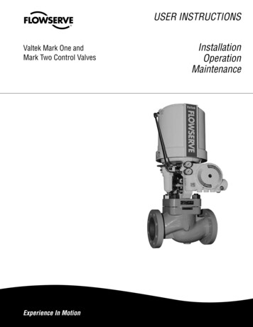
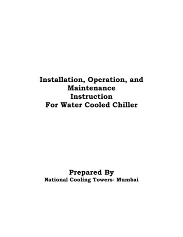
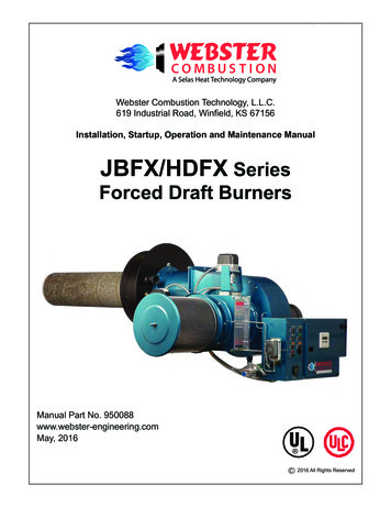
TABLE OF CONTENTSSafety Precautions . 2A. Introduction . 3Burner Model Number . 5JBFX/HDFX Dimensions . 6B. Component ldentification . 8C. Installation . 11D. Special lnstructions For Canadian lnstallations . 12E. Burner Mounting Criteria . 13F. Fuel Systems . 14G. Initial Settings . 17H. Ignition Systems . 18I. Start-up & Operating Adjustments . 19J. Troubleshooting . 22K. General Maintenance and Care . 24L. Care of The Burner During Extended Shutdown . 26M. Replacement Parts . 26N. Warranty Validation & Field Start-up Report .26NOTES .28A. INTRODUCTIONThis manual covers the Models JBFX and HDFX burnersoffered by Webster Combustion Technology, LLC. Theseburners can be used in a wide variety of Cast Iron, Firebox, Firetube, Flextube and other applications. They canfire natural gas or propane with several differentoperating systems.READ AND SAVE THESE INSTRUCTIONS FORREFERENCE.1. Nameplate InformationEach burner has a nameplate with important job details,similar to the nameplates shown in Figure A-1. The “X”in the model number refers to a low NOx burner.Figure A-1 NameplateWARNINGDO NOT ATTEMPT TO START, ADJUST OR MAINTAIN THIS BURNER WITHOUT PROPER TRAININGOR EXPERIENCE. FAILURE TO USE KNOWLEDGEABLE TECHNICIANS CAN RESULT IN EQUIPMENTDAMAGE, PERSONAL INJURY OR DEATH.The startup and maintenance of the JBFX and HDFXburners requires the skill of an experienced and properlytrained burner technician. Inexperienced individualsshould not attempt to start or adjust this burner.Every attempt has been made to accurately reflect theburner construction, however, product upgrades andspecial order requirements may result in differencesbetween the content of this manual and the actual equipment. These special components will be described in theinformation provided with the burner and should be usedas the controlling document.NOTE: This manual must be readily available to alloperators and maintained in legible condition.Metal Fiber Burner ManualMODEL NUMBERSERIAL NUMBERJBFX1G-47-10-LMV37-M.10-CSDIU110539A-01GAS INPUT ATURAL GASVOLTSAMPSHERTZPHASECONTROL CIRCUIT1155.0601BURNER MOTOR2084.1603HP1.0The serial number represents the unique number for thatburner and is a critical number that will be needed for anycommunications with Webster Engineering.The input rates define the maximum and minimum inputs forthat burner, given in MBH for gas.The electrical ratings of the burner are given, with the voltage,current load, frequency and phase (this will either be singleor 3-phase). For motors, the motor HP is listed.Page 3Introduction
2. RatingsThe ratings for each specific burner are given on thenameplate. The general burner ratings are given inSpecification Sheets that follow this section. Themaximum inputs are given based on the type of fuel.Other conditions, like the supply gas pressure or thecombination of fuels, emission requirements and controlsystems, may prevent the burner from reaching thelowest firing rate.All of these documents are needed to support theinstallation and startup of the unit. These additionalitems include:a. The wiring diagram, which shows the limits andinterconnection of the burner and vessel controls.b. The gas piping schematics, which show thecomponents and their relative positions in thepiping train.c. The unit material list which provides an overview ofthe burner requirements and a complete bill ofmaterial, including the part numbers and descriptionfor each item.d. The flame safeguard manual provides theoperating sequence for the burner managementsystem. This will be a critical document for troubleshooting any future problems.e. Catalog cuts of the major components. Theseprovide details on the installation, adjustment andmaintenance of the components used on the burner.3. Product OfferingThe JBFX/HDFX burner can fire natural gas, propaneand digester gas.This burner is a low emmision burner capable of firingsub 20ppm NOx or sub 9ppm NOx, depending on therequirements of the particular burner application.Figure A-2 lists the common variations and optionsavailable on this product. The minimum furnaceconditions are given in Section C.4. Your Complete ManualIn addition to this manual, there are several otherdocuments that should be considered as part of thecomplete manual for the burner.5. Service, Parts and other InformationService and parts are available from your local WebsterRepresentative. For a list of Webster Representatives,please call 620-221-7464, or visit the Webster web site:www.webster-engineering.comMetal Fiber Burner ManualPage 4Introduction
MODEL JBFX BURNER MODEL CONFIGURATIONFIGURE A-2JBFX1G-40-07-RM7800L-M.25-M-UL/CSD-1BURNER SERIESCODES ANDLISTINGSJBFJBF SERIESHDF HDF SERIES“X” denotes Low NOxULULcCSD-1BLOWER HOUSING SIZEFMIRIFUELSGNat. GasLPPropaneSGDigesterNFPA-85Boiler HorsepowerBLOWER MOTORHORSEPOWER031/3051/2073/4101151.5202303505GAS TRAIN VENDORVGDSiemensVGGSiemensMMaxonBlankAll Others(ASCO) - (std)GAS TRAIN SIZEFLAME SAFEGUARDVENDOR DESIGNATIONRM7800LHoneywellM MarkAutoFlame - mini ens.151 1/2 inches.202 inches.252 1/2 inches.303 inches.404 inchesGAS SYSTEMMModulationThe above represents the common model designations.Contact the factory for other options and special applications.Metal Fiber Burner ManualPage 5Identification
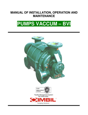
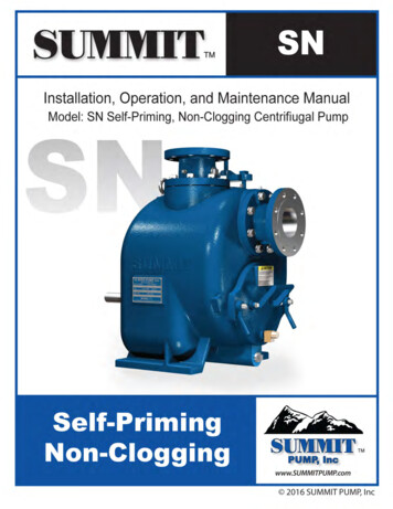
Model JBFX Series Typical Dimensions (Inches)HDFX Side ViewMetal Fiber Burner ManualHDFX Back ViewPage 6Specification
JBFX Side ViewJBFX Back ViewFuels Burned and Control Systems- Natural Gas, Propane, Digester or Mixed Gases- Modulating- Control Circuit Requires 120 vac, 60 Hz, Single Phase Voltage SupplyModel JBFX burners are listed by Underwriters Laboratories, Inc. (UL / ULC) and can bepackaged to meet specific requirements of IRI, FM, GE GAP, NFPA, MIL spec. or other specialinsurance or local code requirements.Model HDFX burners are not listed by Underwriters Laboratories Inc (UL/ULC) but can bepackaged to meet specific requirements of IRI, FM, GE GAP, NFPA, MIL spec. or other specialinsurance or local code requirements.Metal Fiber Burner ManualPage 7Specification
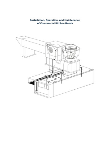
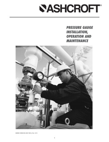
B. COMPONENT IDENTIFICATIONThis secion shows the different common components used in the JB burner line and should be helpful to identify partsdescribed elsewhere in this manual.FrontplateServerBlower HousingFigure B-1JBFX BurnerAir FilterLight & Switch PanelControlCabinetBlower MotorControl sionAir Flow SwitchAir FilterSwitchPilotGas Gas ValveActuatorFigure B-2JBFX Burner Side ViewMetal Fiber Burner ManualPage 8Pilot TrainIdentification
Rear AccessCoverManifold/HeadFigure B-3HDFX BurnerBlowerHousingAir FilterTAT SensorLouver BoxBlower MotorFrontplateTAT Panel (Top)Electrical J-Box (Bottom)Figure B-4HDFX BurnerBack ViewCombustionHeadScannerMountPilotPilot TrainGas ValveMetal Fiber Burner ManualGas ServoLouver Box ServoPage 9Identification
Figure B-5Control PanelOn-Off SwitchControl RelaysManual PotentiometerRate ControlPower On LightFuel On LightAlarm Silencing Switch(Optional)Manual-Auto SelectorSwitchTransformer FusesControl TransformerBurner MotorStarterCall for Heat LightLow Boiler Water LevelLight (Optional)Flame SafeguardAlarm BuzzerAlarm LightTerminal StripMetal Fiber Burner ManualPage 10Identification
C. INSTALLATIONPrior to installing the burner, the site conditions andutilities need to be evalulated. This section providessome general questions that can help the reviewprocess. Inspect the burner for any undetected damage that may have occurred during shipment or byjobsite handling. Special attention should be given tothe control panel and protruding parts such as linkages.Check linkages, air louver stops, wiring connections andfasteners for tightness. Also check head to ensure nodamage has occured to the metal fiber surface duringshipment.Verify that all ship loose (or separately shipped) itemsare on hand. This normally will be gas train components, mounting lugs and insulating rope. Also, frontmounting plate with attached combustion head. Theburner material list included with the instruction manualserves as a good checklist for this purpose.1. Is there adequate outside ventilation to supply theneeded air for safe combustion as required by yourlocal regulatory agency?2. If a burner mounting plate is required, is it availableand does it meet specifications? (See Section E.)3. Is 120-60-1 voltage available for the control circuitand is the correct voltage available for the blowermotor?4. Will the burner properly fit the boiler or heater withample clearance on top, bottom and sides?5. Will there be adequate gas pressure to assure thespecified firing rate?6. Is there adequate flue provisions to assure SAFEand proper venting of the burner?7. All manuals should be reviewed and understoodand stored in a convenient place.8. Teflon tape should not be used on any field piping.9. Rope gaskets should be used between vessel andmounting plate.10. Gas piping should be flushed (cleaned) prior to use.11. Check minimum straight lengths for gas pressureregulator and/or sensing line.12. If multiple vessels connect to a single stack, are theysized and designed to maintain /- 0.1” draft at thevessel outlet under all operating conditions.13. Is stack designed to maintain /- 0.1 at outlet duringall operating conditions.14. Is the burner mounting plate and burner head sealedwith rope gasket? (See Figure B-2.)15. Is there a drop leg in the gas supply to captureforeign material? (See Figure C-1.)16. Is the piping b
Specification Sheets that follow this section. The maximum inputs are given based on the type of fuel. Other conditions, like the supply gas pressure or the combination of fuels, emission requirements and control systems, may prevent the burner from reaching the lowest firing rate. 3.