Transcription
MANUAL OF INSTALLATION, OPERATION ANDMAINTENANCEPUMPS VACCUM – BVI"Quality Management SystemISO 9000:2008."
Mr. ProprietaryCongratulations! You just buy a simple construction equipment, designed andmanufactured with the latest technology, excellent performance and easy maintenance.This manual details the report on building, correct procedures for installation, operationand maintenance, and care should be observed so that the equipment has prolongedlife, playing its role in the most efficient way to the application which was intended.The IMBIL recommends that the equipment is installed and maintained as required bygood technique and with the instructions contained in this Manual is not responsible fordamages resulting from breach of the provisions contained therein.The IMBIL also recommends that this manual is used by personnel trained andresponsible for installation, operation and maintenance of equipment.For queries on the ordering of equipment or spare parts, please indicate the code ofthe piece, type of bomb, number of test indicated on the nameplate for identificationand stored in low relief on the suction flange.The IMBIL that calls to you as soon as receive The guarantee of your equipment, fillout and send the data to the left IMBIL, facilitating the exchange of information betweenthe User and IMBIL.1
ÍNDICE1.1.12.2.12.22.3HOW THE WORK vacuum pump IMBIL . 04Principle of Operation. 04RECEIPT AND SURVEY . 05Preliminary Inspection . 05Initial Care . 05Storage . 23.6.3INSTALLATION OF VACUUM PUMP . 06Choice of Venue. 06Preparation of Foundation . 06Settlement and Leveling . 06TRANSMISSION. 08Transmission by Direct Coupling . 08Set of Transmission by Belts and Pulleys. 09Pipe Distributors and Collectors . 10Distributor Tube Input. 10Tube Collector Output . 11PIPES . 11Tubing or vacuum suction . 11Pipe Output of discharge or . 12Silencer - Tab Downloads . 1244.14.24.2.14.2.2.4.3The vacuum CONTROLS AND LIQUID COMPRESSOR . 14Control and adjustment of vacuum levels . 14CONTROL AND ADJUSTMENT OF NET COMPRESSOR. . 15União de Orifício Calibrado: .15Regulation of the Net Compressor:.16Diagrams of Lines in Hydraulic Fluid Power Compressor . 1655.15.25.35.4SYSTEMS OF SEALING IN VACUUM PUMP. 17Set of gasket for sealing . 17Drip. 17Hydraulic Sealing by sealing . 17Sealing by mechanical seal . 176DOWNLOAD AND DRAINAGE OF vacuum pump . 1877.17.2PARADAS PROLONG AND STORAGE . 19Paradas prolonged . 19Storage . 198LIST OF PARTS . 2099.1.19.1.29.1.39.1.49.1.59.1.69.2DISMANTLING AND ASSEMBLING . 21Preparation for Disassembly . 21Top of Disassembly. 21Extraction of Bearings . 22Removal of Cones. 23Assembly-disassembly of Girante (Rotor-axis) . 23Internal Inspection . 23Mounting . 242
9.2.19.2.29.2.39.2.49.2.59.2.69.2.7Assembly of the Joint Girante (Rotor-axis) . 24Settlement of Cones. 24Mounting Position. 24Mounting of Body, Set-Girante and Side . 26Placing of Bearings . 27Axial adjustment and Folga . 27Closing and locking of the vacuum pump . 281010.1LUBRICATION . 29Care Bearings . 2911POSSIBLE FAILURE OF OPERATION . 311212.112.2TECHNICAL ASSISTANCE AND SPARE PARTS . 33Technical Assistance . 33Spare Parts . 3313WARNING - CARE AND PRECAUTIONS . 3414TECHNICAL ADVICE . 3515CUSTOMER SERVICE . 363
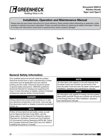
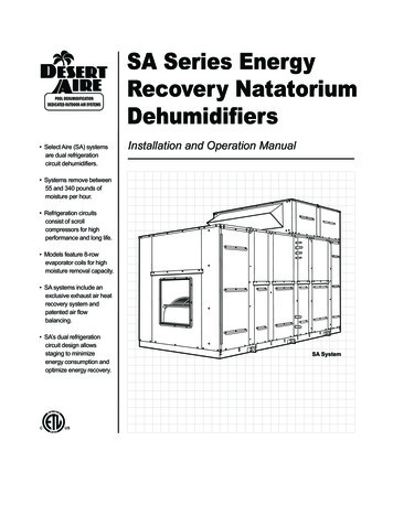
1. HOW THE WORK VACUUM PUMP IMBIL1.1.Principle of Operation:The vacuum pumps are manufactured by IMBIL rotary-ring type of liquid having asingle set girante (Rotor-axis) without any contact between solid materials, with onlythe friction between liquid and metal, which guarantees them non-aggressive in termsof use, extremely long life.The working principle is based on the existence of cameras distributed in a rotoreccentrically positioned cylindrical body called a carcass or body. The spaces betweenthe rotor blades flat, the body and side covers forming chambers are filled with liquid(or liquid compressor seals), which under the action of the centrifugal force imposed byrotation of the rotor, causing the change in volume of each cell, due to thedisplacement of the liquid against the body, drawing and compressing gas in thechambers, a similar action performed by pistons.With the rotation of the rotor, the liquid compressor driven against the wall inside thecylindrical body, takes the form of a ring, from which comes the name "Ring of vacuumpump fluid.Inside the vacuum pump as two distinct areas of action occurs where the aspiration ofthe gases in the zone of expansion and expulsion in the same area of compressionrespectively.Gases reach the chambers of the rotor, through the windows of the larger conesfollowed by smaller windows to the same ex-pump vacuum.The liquid or Sealing Compressor through the cones, being introduced through theexisting connections in the side covers of the equipment.By the nozzle into the sides or simply called Covers, Side air, gases or vapors enter thevacuum pump, and expelled through the nozzles to discharge (output) with the fluidcompressor.The figure below shows the working principle of generator equipment for Liquid RingVacuum type.ENTRADACONEASPIRAÇÃO (SUCÇÃO)GASESCORPO (CARCAÇA)ZONA DE EXPANSÃOROTORANEL LÍQUIDOSENTDO DEROTAÇÃOSAÍDA (DESCARGA)LATERALJANELA MAIORGASES ( ) LÍQ. COMPRESSORPALHETAZONA DE COMPRESSÃOJANELA MENOREIXOFigura 14
2. RECEIPT AND SURVEY2.1PRELIMINARY INSPECTION:2.1.1. Upon the receipt of any supply IMBIL, you should inspect each equipment,garment, accessory or assembly related (s) in the list (s) of Material (s) according to (s)Note (s) Tax ( s).Vacuum pumps with their drive motors, are generally shipped assembled and coupledon a common basis.Transfers through games of Pulleys or Elastic gloves, is provided packed the party, notto suffer damage during transport.2.2 .INITIAL CARE:2.2.1. Both electric motors as the axis of vacuum pumps may be misaligned at thetime of arrival to you, with the same run the correct alignment and engagementwith your installation.2.2.2. The sets should preferably be transported or moved through four or more pointsof support or base or handle packaging.2.3 .STORAGE:2.3.1. If the vacuum pump be installed and put into operation soon after their arrival,there should be storage in the clean and dry. It is advisable to rotate the axis ofthe pump manually every 10 days or 15 days, for lubrication of bearings andavoid crashes of all-girante, due to possible oxidation or corrosion of the same.Every vacuum pump is immersed in oil soluble, to protect the set-girante andthe same before its release for shipment. Prolonged storage should follow theinstructions in this manual for the period you need2.3.2. As usually the Games Pulleys, Elastic gloves for direct coupling, ElectricalPanels, etc., Is provided packed, it is advisable to be kept under the sameconditions the receipt, not to suffer damage during storage.2.3.3. During storage it is desirable that all equipment is properly covered withtarpaulins or plastic for adequate protection against weather or external agents.5
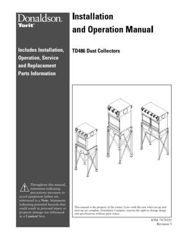
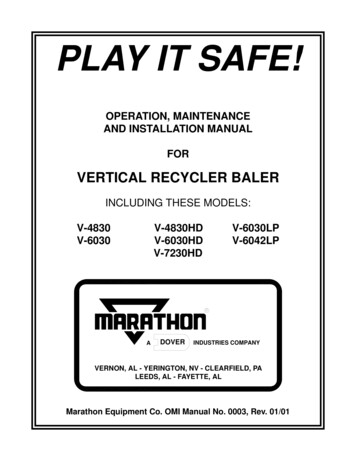
3. INSTALLATION OF VACUUM PUMP3.1.Choice of Venue:Vacuum pumps of Liquid Ring must be installed in places closest possible pointof demand. Must also be settled near sources of water supply, electricity, besides theplaces of destination of the liquid compressors, gas, air and vapor.3.2.Preparation of Foundation:The foundation must be designed and implemented in accordance with localconditions exist for you to support all loads that will be imposed without allowingdisplacements of equipment on which it will be settled.The foundation concrete is the most used, not only for its rigidity, as well as thesimplicity of implementation.The top of the foundation should be placed at a depth of 12mm to 30mm of thefloor level.In the introduction of chumbadores in particular, you should provide sufficienttime for the same points that allow for the placement of shorts, base, washers, nutsand implementation of the final surface with mortarIt is advisable to place a tube of about 75mm at the tip of each anchor bolts inconcrete, to facilitate the alignment of these holes with the metal base on which theequipment will be seated figures 2, 3 and 4 show in detail the forms of implementation.The diameters of the holes in the base metal should be slightly larger than the anchor.Figura 3Figura 26
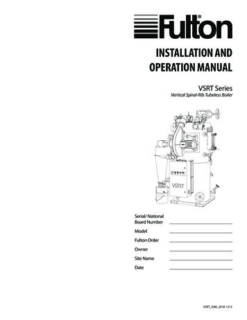
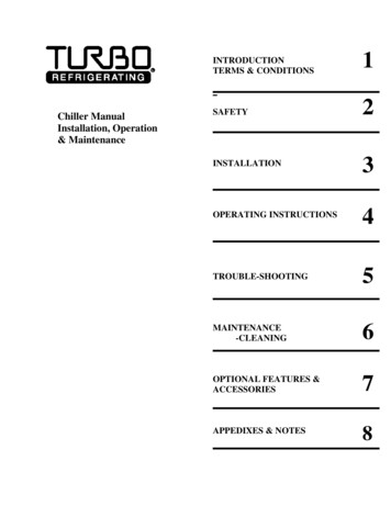
Figura 4For the positions where they are located chumbadores the flat between them, itis suggested that metal plates put lead in the finishing mortar with the aid of "levels", asshown in Figures 5 and 6.Loads in the concrete should not exceed 20 kgf/cm2, so there should be metalplates whose surfaces do not allow this pressure on the concert is over.For alignment, leveling and final assembly of the equipment, it is important thatthe concrete is cured to reach its full working conditions.Even if the cure last few days, it is preferable to await the total cure of the concrete,than to anticipate the settlement of charges that may cause misalignments sar calços se necessárioFigura 53.
If the vacuum pump be installed and put into operation soon after their arrival, there should be storage in the clean and dry. It is advisable to rotate the axis of the pump manually every 10 days or 15 days, for lubrication of bearings and avoid crashes of all-girante, due to possible oxidation or corrosion of the same. Every vacuum pump is immersed in oil soluble, to protect the set-girante .