Transcription
USER INSTRUCTIONsUser instructions - Mark One - VLENIM0001-01 07.07 Valtek Mark One andMark Two Control ValvesInstallationOperationMaintenance
User instructions - Mark One - VLENIM0001-01 07.07 Contents1. General Information2. Unpacking3. Installation4. Quick Check5. Valve Maintenance6. Disassembly and Inspection7. Assembly and Installation8. Severe Service Trim Options8.1. CavControl8.2. ChannelStream8.3. MegaStream8.4. Stealth8.5. TigerToothFiguresFigure 1 – Mark One Control Valve Body AssemblyFigure 2 – Pressure Balanced Mark One Control Valve Body AssemblyFigure 3 – Exploded View Mark One Body AssemblyFigure 4 – Soft Seat AssemblyFigure 5 – Actuator Stem / Stem Clamp AlignmentFigure 6 – Mark One with CavControl Trim Body AssemblyFigure 7 – Mark One with ChannelStream Trim Body AssemblyFigure 8 – Mark One with MegaStream Trim Body AssemblyFigure 9 – Mark One with Stealth Trim Body AssemblyFigure 10 – Mark One with TigerTooth Trim Body AssemblyTablesTable I – Common LubricantsTable II – Suggested Bonnet Bolting Torque ValuesTable III – Troubleshooting Chart
User instructions - Mark One - VLENIM0001-01 07.07 1.General Information1.1.UsingThe following instructions are designed to assist inunpacking, installing and performing maintenanceas required on Flowserve products. Product usersand maintenance personnel should thoroughly reviewthis bulletin prior to unpacking, installing, operating, or performing any maintenance. In most cases,Flowserve valves, actuators and accessories are designed for specific applications (e.g. with regard tomedium, pressure, and temperature). For this reason,they should not be used in other applications withoutfirst contacting the manufacturer. The product Installation, Operation, and Maintenance Instructions provides important additional safety information.1.2.1.3.1.3.1.STOP!ApplicabilityThe following instructions are applicable to the maintenance and installation of Flowserve Valtek Mark Oneand Two control valves. These instructions cannotclaim to cover all details of all possible product variations, nor can they provide information for every possible example of installation, operation or maintenance.This means that the instructions normally include onlythe directions to be followed by qualified personal using the product for its defined purpose. If there are anyuncertainties in this respect, particularly in the eventof missing product-related information, clarificationmust be obtained via the appropriate Flowserve salesoffice. All Flowserve User Manuals are available atwww.flowserve.com.Terms Concerning SafetyThe safety terms DANGER, WARNING, CAUTION andNOTE are used in these instructions to highlight particular dangers and/or to provide additional informationon aspects that may not be readily apparent.DANGER: Indicates that death, severe personal injuryand/or substantial property damage will occur if properprecautions are not taken.WARNING: Indicates that death, severe personal injuryand/or substantial property damage can occur if properprecautions are not taken.CAUTION: Indicates that minor personal injury and/orproperty damage can occur if proper precautions arenot taken.NOTE: Indicates and provides additional technical information, which may not be obvious, even to qualifiedpersonnel.1.3.2.Compliance with other notes, which may not be particularly emphasized, with regard to transport, assembly,operation and maintenance and with regard to technical documentation (e.g. in the operating instructions,product documentation, or on the product itself) isessential, in order to avoid faults, which can directlyor indirectly cause severe personal injury or propertydamage.1.4.Protective ClothingDANGER: Flowserve products are often used in problematic applications (e.g. under extremely high pressures with dangerous, toxic or corrosive mediums).When performing service, inspection, or repair operations, always ensure that the valve and actuator aredepressurized and that the valve has been cleaned andis free from harmful substances. In such cases, payparticular attention to personal protection (e.g. protective clothing, gloves, glasses etc.).1.5.Qualified PersonnelQualified personnel are people who, on account of theirtraining, experience and instruction and their knowledge of relevant standards, specifications, accidentprevention regulations and operating conditions, havebeen authorized by those responsible for the safety ofthe plant to perform the necessary work and who canrecognize and avoid possible dangers. Contact yourlocal Flowserve representation for a schedule of training schools.1.6.Spare PartsUse only Flowserve original spare parts. Flowservecannot accept responsibility for any damages that occur from using spare parts or fastening materials fromother manufactures. If Flowserve products (especiallysealing materials) have been on store for long periodsof time check them for corrosion or deterioration before putting them into use.1.7.Service / RepairTo avoid possible injury to personnel or damage toproducts, safety terms must be strictly adhered to.Modifying this product, substituting non-factory parts,or using maintenance procedures other than thoseoutlined in these Installation, Operation, and Maintenance Instructions could drastically affect performance, be hazardous to personnel and equipment, andmay void existing warranties. Between the actuatorand the valve there are moving parts. To avoid injury,Flowserve provides pinch-point-protection in the formof cover plates, especially where side-mounted posi-
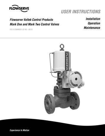
User instructions - Mark One - VLENIM0001-01 07.07 Plug(Item # 50)Upper Guide(Item # 87)Upper Packing(Item # 88)Body Bolting(Item # 108/114)Bonnet Flange(Item # 70)Bonnet(Item # 40)Packing Spacers(Item # 94-99)Lower Packing(Item # 83)Lower Guide(Item # 83)Bonnet Gasket(Item # 58)Body(Item # 1)Seat RingSeatRetainer(Item # 20)Seat Gasket(Item # 30)(Item # 55)Figure 1: Mark One Control Valve Body Assembly
User instructions - Mark One - VLENIM0001-01 07.07 STOP!tioners are fitted. If these plates are removed for inspection, service or repair special attention is required.After completing work the cover plates must be refitted. Apart from the operating instructions and theobligatory accident prevention directives valid in thecountry of use, all recognized regulations for safetyand good engineering practices must be followed.WARNING: Before products are returned to Flowservefor repair or service, Flowserve must be provided witha certificate that confirms that the product has beendecontaminated and is clean. Flowserve will not accept deliveries if a cleaning certificate has not beenprovided. Return authorization is also required beforeparts are returned. Contact your local Flowserve representative to obtain return authorization.1.8.StorageIn many cases, Flowserve products are manufacturedfrom stainless steel. Products not manufactured fromstainless steel are provided with an epoxy resin coating. This means that Flowserve products are wellprotected from corrosion. Nevertheless, Flowserveproducts must be stored adequately in a clean, dryenvironment. Plastic caps or plywood protectors arefitted to help protect the flange faces and prevent theingress of foreign materials. These caps should not beremoved until the valve is actually mounted into thesystem.2.Unpacking2.1.2.2.STOP!2.3.2.4.While unpacking the valve, check the packing listagainst the materials received. Lists describing thevalve and accessories are included in each shippingcontainer.When lifting the valve from shipping container, usestraps through the yoke legs, or the lifting lugs attached to the body bolting for valves over four inch,or the adjusting screw for valves four inch and under.Take care to position lifting straps to avoid damage tothe tubing, mounted accessories, or stroke plate.WARNING: When lifting a valve be aware that the centre of gravity may be above the lifting point. Therefore, support must be given to prevent the valve fromrotating. Failure to do so can cause serious injury topersonnel and damage to the valve and nearby equipment.Contact your shipper immediately if there is shippingdamage.Should any problem arise, call your Flowserve InstallationDANGER: Before installation check the purchase order number, serial number, and/or the tag number toensure that the valve and actuator being installed arecorrect for the intended application.WARNING: The maximum air supply for most Valtekcylinder actuators is 150 psi (10.3 bar). In some cases, the air supply must be limited to less than 150psi (10.3 bar). This is indicated on a sticker foundnear the upper air port on the actuator cylinder. Anair regulator should be installed to ensure the supplypressure does not exceed the actuator design pressure indicated on the sticker.CAUTION: Do not insulate extensions that are provided for hot or cold services.CAUTION: On valves equipped with air filters, the airfilter must point down to perform properly.NOTE: Selecting the proper fastener material is theresponsibility of the customer. Typically, the supplierdoes not know what the valve service conditions orenvironment may be. Flowserve‘s standard body bolting material is B7/2H. B8/8 (stainless steel) is optionalfor applications more than 800 F / 425 C and withstainless steel or alloy body valves. The customertherefore must consider the material‘s resistance tostress corrosion cracking in addition to general corrosion. As with any mechanical equipment, periodicinspection and maintenance is required. For moreinformation about fastener materials, contact yourFlowserve representative.Pipelines must be correctly aligned to ensure that thevalve is not fitted under tension.Fire protection must be provided by the user.Before installing the valve, clean the line of dirt, welding chips, scale and other foreign material.Whenever possible, the valve should be installed inan upright position. Vertical installation permits easiervalve maintenance. This is also important for cryogenic applications to keep the packing isolated fromthe flowing medium, permitting the packing temperature to remain close to ambient temperature.Be sure to provide proper overhead clearance for theactuator to allow for disassembly of the plug fromthe valve body. Refer to the appropriate actuator UserInstructions for proper clearances. Actuator User Instructions are available at www.flowserve.com.Double-check flow direction to be sure the valve isinstalled correctly. Flow direction is indicated by thearrow attached to the body.If welding the valve into the line, use extreme care toavoid excess heat buildup in the valve.
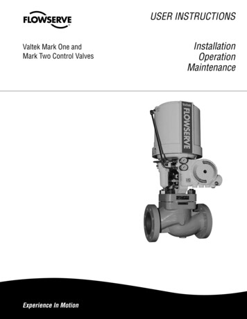
User instructions - Mark One - VLENIM0001-01 07.07 Figure 2: Pressure Balanced Mark One Control Valve Body Assembly3.8.STOP!3.9.4.4.1. If the valve has separable end flanges, verify that thehalf rings are installed on the valve body before boltingthe valve into the line.WARNING: Failure to install half rings on the valvebody can cause serious personal injury.Connect the air supply and instrument signal lines.Throttling control valves are equipped with a valve positioner. Refer to the appropriate positioner bulletin forconnections, maximum air supplies, and maintenanceinstructions. An air filter should be installed before thepositioner. All connections must be free of leaks.CAUTION: On valves equipped with air filters, the airfilter must point down to perform properly.Quick-checkPrior to start-up, check the control valve by followingthese steps:Stroke the valve and observe the plug position indicator on the stem clamp compared to the stroke indica-STOP!4.2.4.3.4.4.tor plate. The plug should change position in a smooth,linear fashion.NOTE: Due to excessive friction a dry graphite packingcan cause the plug stem to move in a jerky fashion.Lubrication of graphite packing will provide smootherstroking. Lubrication can be done by using a bonnetlubricator or by liberally coating each packing ring byhand during installation. Please refer to Table I for listsof common lubricants.WARNING: Keep hands, hair and clothing away fromall moving parts when operating the valve. Failure todo so can cause serious injury.Check for full stroke by making appropriate instrumentsignal changes.Check all air connections for leaks.Check packing box bolting for the correct adjustment.Refer to the packing installation manual for specificdetails on maintaining the style of packing supplied.
User instructions - Mark One - VLENIM0001-01 07.07 4.5.5.5.1.5.2.5.3.5.4.5.5.5.6.CAUTION: Do not overtighten packing. This can causeexcessive packing wear, high stem friction that mayimpede plug movement and can damage the packing.Over-tightening packing will not improve the stemseal unless the packing has been previously damaged.Damaged packing should be replaced.Make sure the valve fails in the correct direction incase of air failure. This is done by turning off the airsupply and observing the failure direction.Valve MaintenanceAt least once every six months, check for proper operation by following the preventative maintenance stepsoutlined below. These steps can be performed whilethe valve is in-line and, in some cases, without interrupting service. If an internal problem is suspected,refer to Section 6, Valve Disassembly and Inspection.Look for signs of gasket leakage through the end flanges and bonnet. Re-torque flange and bonnet bolting (ifrequired). Refer to Table II for bonnet bolt torque values.Examine the valve for damage caused by corrosivefumes or process drippings.Clean valve and repaint areas of severe oxidation.Check packing box bolting for proper tightness andpacking leakage. If packing leakage is noticed, packingmaintenance is required. Refer to the packing installation manual (document number VLAIM040) for specific details on maintaining the style of packing supplied.CAUTION: Do not overtighten packing. This can causeexcessive packing w
tenance and installation of Flowserve Valtek Mark One and Two control valves. These instructions cannot claim to cover all details of all possible product varia-tions File Size: 783KBPage Count: 16