Transcription
Technical BulletinIssue Date11/01/01TECHNICAL BULLETINTroubleshooting Variable Air Volume Modular Assembly(VMA) 1400 Series ControllersTroubleshooting VMA1400 Series Controllers.3Introduction. 3Key Concepts. 5Troubleshooting VAV System Operation .5Hardware Concerns.6VMA Control Performance Measures .9Occupant Hot/Cold Complaints .12VMA LED Indicator Status .14Tools for Detecting Communication Problems .14N2 Bus Communication Problems .14Zone Bus Problems .15Lack of Heat During Commissioning.16Detailed Procedures. 17Detecting Airflow and Temperature Problems.17Troubleshooting Airflow Leakage at a Fully Closed Damper.20Troubleshooting Low Air Velocity.20Correcting Distorted Flow Patterns Due to Duct Design .20Correcting Unstable Sensor (AI) Readings .21Checking Flow Problems by Verifying Velocity Pressure Sensor Operation .22Checking Airflow Pickups for Debris or Water.22Checking for Incorrectly Wired Sensors and Misapplied Room Assignments .23Troubleshooting Balancer’s Flow Reading.24Detecting Communication Problems Using the VMA LED .24Identifying N2 Bus Configuration Problems .25Testing for N2 Bus Opens, Shorts, and Crossed Wires .26Verifying Proper Transformer Installation.27 2001 Johnson Controls, Inc.Code No. LIT-6363135www.johnsoncontrols.comSoftware Release 5.0
2Troubleshooting VMA1400 Series Controllers Technical BulletinChecking for Proper Device Isolation and Ground Loops .27Troubleshooting Heating Problems.28
Troubleshooting VMA1400 Series Controllers Technical Bulletin3Troubleshooting VMA1400 SeriesControllersIntroductionAlthough the Variable Air Volume Modular Assembly (VMA) hasbeen designed to provide years of reliable service, problems candevelop in the related building and Heating, Ventilating, and AirConditioning (HVAC) systems. Problems involving the VMA usuallysurface in the form of occupant comfort issues or communicationfailures. The causes of these problems range from device failures toHVAC system maintenance and design issues, installation errors, orchanges in use of a zone. Troubleshooting must consider all of thesevariables.Note:This document focuses on the VMA1410, 1420, and1430 controllers. The VMA1400 Series also includes theVMA1440, which is used exclusively as part of theMetasys Zoning Package. See the Metasys Zoning PackageProduct Bulletin (LIT-639050) and the Metasys ZoningPackage Overview Technical Bulletin (LIT-639100) forinformation on this specialized product.This document describes how to: detect airflow and temperature problems troubleshoot airflow leakage at a fully closed damper troubleshoot low air velocity correct distorted flow patterns due to duct design correct unstable sensor (Analog Input [AI]) readings check flow problems by verifying velocity pressure sensoroperation check airflow pickups for debris or water
4Troubleshooting VMA1400 Series Controllers Technical Bulletin check for incorrectly wired sensors and misapplied roomassignments troubleshoot Balancer’s flow reading detect communication problems using the VMA Light-EmittingDiode (LED) identify N2 Bus configuration problems test for N2 Bus opens, shorts, and crossed wires verify proper transformer installation check for proper device isolation and ground loops troubleshoot heating problemsNote:Where this document refers to HVAC PRO software,substitute EURO PRO in Europe.
Troubleshooting VMA1400 Series Controllers Technical BulletinKey ConceptsTroubleshooting Variable Air Volume (VAV) System OperationController Configuration ProblemsMechanical, flow, and wiring problems occur far more often thanconfiguration problems. This is especially true sinceProportional-Integral-Derivative (PID) loop tuning is automatic withthe VMA.As a rule of thumb, ensure all the equipment and wiring in the systemchecks out before investigating errant configuration parameters inHVAC PRO software.Refer to the HVAC PRO User’s Guide for more information whenreviewing VMA configuration parameters.HVAC PRO SoftwareHVAC PRO software provides various diagnostics to help youpinpoint temperature and airflow control problems. Controllerinformation, VAV Box Flow Test, Collect VAV Diagnostics, and theVMA Balancer Tool each have a role in diagnosis and correction ofVariable Air Volume (VAV) system problems, whether mechanical,electrical, or configuration related.Collected and calculated data about VMA inputs, outputs, and controlloop performance can be displayed through the Parameters list box inthe Commissioning mode. Refer to the HVAC PRO User’s Guide formore information when using HVAC PRO tools.VAV Box Flow TestThis test is provided in HVAC PRO software to collect flowcharacteristics for the VMA. It can help determine if the VMA ismaintaining minimum flow for ventilation and for staged electricreheat. It can also check for maximum flow and diagnose a starvedbox, reversed polarity, or a loose set screw on an actuator.5
6Troubleshooting VMA1400 Series Controllers Technical BulletinHardware ConcernsSensor ErrorsZone temperature and pressure sensor errors can cause controlproblems. The Analog Input (AI) range may be improperly selected inthe HVAC PRO configuration file. The sensor may need an offset forcable length. This offset, whose default value is -0.8 C (-1.5 F), is anattribute of the Zone Temperature AI. In addition, the sensor may beimproperly installed or an element may be damaged. Sensor errors canoccur when the temperature sensor is affected by the sun, other zones,or supply air from the diffuser.In the worst case, the Differential Pressure (DP) sensor may drift up to 0.1793 Pascal per C ( 0.0004 inch W.C. per F). This is usuallyinsignificant. However, it may produce noticeable flow measurementerror during periods of large ambient temperature change. Examples ofsuch periods are transitions between unoccupied and occupied, orduring project startup when electrical power may be off and buildingtemperature is not controlled. The controller autocalibrates the DPsensor every two weeks by default to offset the long term affects oftemperature and humidity changes. If greater flow measurementaccuracy is required at low flow rates where box inlet velocity is under1 m/s (200 fpm [feet per minute]), the Autocalibration Period can bereduced to recalibrate every three hours.IMPORTANT: During Autocalibration, airflow to the zone drops tozero for the following durations (worst case):VMA1410/1420 90 seconds (30 seconds to driveopen 30 seconds to drive close 30 seconds sensorsettle time)VMA1430 the sum of the damper actuator stroketime and 30 seconds (amount of time to drive close 30 seconds sensor settle time)Damper/Actuator OperationDamaged damper seals, bent damper blades, poorly designed dampers,or a mis-aligned actuators can cause air leakage during the fully closedposition. This causes a small offset that the Balancer can usuallycompensate for. However, if tight shutoff is required for theapplication, replace the defective VAV box.
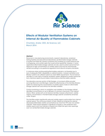
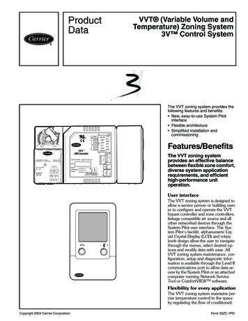
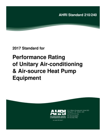
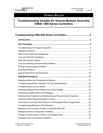
7Troubleshooting VMA1400 Series Controllers Technical BulletinDuctwork DesignAir velocity is non-uniform if turns or transitions in hard duct or sagsin flexible duct are within close proximity to the flow pickups. In thiscase, the pickup ports may not represent the true average air velocity.In addition, different flow rates may distinctly change the velocityprofile.A minimum of three duct diameters of straight, unrestricted ductupstream from the airflow pickups is recommended. The flow profileproblem can be corrected by installing straightening vanes in theoffending duct section or changing the duct configuration to providegreater separation between the transition and the pickup.Flow rate measurement problems can also be caused by a duct lengththat causes significant pressure drop or by sags present in flexible duct.This can also be avoided by installing hard duct three diameters inlength, starting at the VAV box inlet.Flow Pickup PerformanceFlow pickup performance suffers when the device is not installedcorrectly. It can also collect debris and must be checked for pluggedports and leaks between the high and low-pressure sides.Air FlowStatic PressureTotal PressureStatic PressurePickup HighPressure ManifoldPickup LowPressure ManifoldArea of Increased Velocityand Decreased PressureDuct WallAirflowFigure 1: Interaction of the Pickup and Air StreamReferencing Figure 1 above, the upstream ports are exposed to totalpressure. In order to sense true static pressure, the pickup must haveopenings that are perpendicular to the direction of flow. Thelow-pressure ports open downstream, and the passing air exerts a pullon these openings, resulting in a pressure less than static. This resultsin airflow pickup gain, resulting in a differential pressure of1.5- to 3-times the velocity pressure.
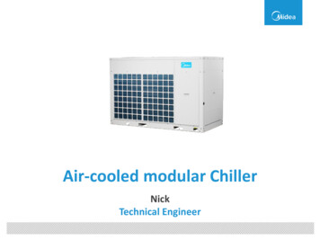
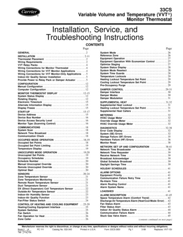
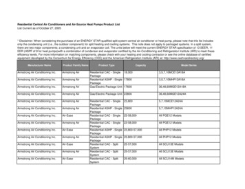
8Troubleshooting VMA1400 Series Controllers Technical BulletinFollowing are typical flow pickup designs. Usually the cross and ringtypes perform better than straight tubes because the sensing ports arebetter distributed across the duct area.Sensing PortsCross TubesSquared RingsStraight TubesSensingFigure 2: Common Flow PickupsVAV Box SizeThe VAV box size and flow pickup gain must be entered accuratelyfor the controller to calculate proper airflow. VAV boxes may beoversized for quieter operation or to reserve cooling capacity. Inletsize and pickup gain for the VAV box are entered inHVAC PRO software during configuration.The size and capacity of the VAV box should match the zone loads.If the installed unit is too small, insufficient cooling results. Inaddition, high flow rates may cause the unit to emit an audible noise. Ifthe installed unit is too large, then proper control of airflow is difficult.
Troubleshooting VMA1400 Series Controllers Technical Bulletin9VMA Control Performance MeasuresTemperature Control MeasuresTable 1 lists key parameters indicating temperature control problems.Table 1: Temperature Control Key ParametersParameterDescriptionMovAvg ZT ErrAverage of the zone temperature control loop error (setpoint minus temperature)over the preceding eight hours of control in normal control modes. This calculationis stopped in Shutdown, Warmup, Low Limit, Water System Flush, and when theZone Temperature sensor is unreliable. If the VMA is interlocked with supply air(fan) availability, and the zone is well designed, this measure should always bewithin 0.5 C ( 1 F). Since controller error is defined as setpoint minus processvariable feedback, negative numbers indicate a warm zone and positive valuesindicate a cold zone.MovAvg ABS ZT ErrAverage of the absolute or unsigned zone temperature control loop error (absolutevalue of setpoint minus temperature) over the preceding eight hours of control innormal control modes. This calculation is stopped in Shutdown, Warmup, LowLimit, Water System Flush, and when the Zone Temperature sensor is unreliable. Itis just like the MovAvg ZT Err, except that the error is always considered positive. Ifthe VMA is interlocked with supply air (fan) availability, and the zone is welldesigned, this measure should always be less than 0.5 C (1 F). Larger values mayindicate a cooling or heating problem, a cycling control, an extended cooldown, orwarmup in progress.Inadequate CoolingWhen True, this indicates the zone cooling demand cannot be satisfied.Specifically, it means the following:Inadequate Heating the controller is calling for cooling the controller is in neither Unoccupied nor Shutdown mode the Zone Temperature is reliable the box is not starved the cooling PID has been saturated high for 15 minutesWhen True, this indicates the zone heating demand cannot be satisfied.Specifically, it means the following: the controller is not in Heating Lockout the controller is calling for heating the controller is in neither Unoccupied nor Shutdown mode the Zone Temperature is reliable the heating PID to be sequenced has been saturated high for ten minutes.This may indicate heating media is not available and Heating Lockout is False.Zone TemperatureStatusIf the sensed value of the zone temperature sensor is outside of the normaloperating range -45 to 121 C (-50 to 250 F) for several readings, the PresentValue of Temperature Loop is Unreliable. This condition is normally caused by anopen or short in the sensor.
10Troubleshooting VMA1400 Series Controllers Technical BulletinAirflow Control MeasuresTable 2 lists key parameters that can indicate airflow control problems.Table 2: Airflow Control Key ParametersParameterDescriptionMovAvg Flow ErrAverage of the flow control loop error (setpoint minus calculated flow) over thepreceding 20 minutes of control in normal control modes. This calculation isstopped in Shutdown, Warmup, Low Limit, Water System Flush, and when theDelta P sensor is unreliable. Since error is (SP – flow), negative numbers indicatea zone with too much flow.MovAvg ABS Flow ErrAverage of the absolute or unsigned flow control loop error (difference betweensetpoint and calculated) over the preceding 20 minutes of control in normal controlmodes. This calculation is stopped in Shutdown, Warmup, Low Limit, WaterSystem Flush, and when the Delta P sensor is unreliable. It is just like the MovAvgFlow Err, except that the error is always considered positive. If the VMA isinterlocked with supply air (fan) availability, and the supply system is well designed,this measure should always be less than the cfm calculated in MovAvg Flow Errabove. Larger values may indicate a lack of supply air, duct blockage ordisconnection, or a damper or actuation problem.Starved BoxWhen True, this indicates the airflow setpoint cannot be satisfied. Specifically, itmeans the controller has been calling for a 100% open damper position for at leastten minutes, and is in neither Unoccupied nor Shutdown, and the Delta P isreliable.Delta P StatusIf the sensed value of the velocity pressure (Delta P) sensor is outside of thenormal operating range for several readings, the Present Value of Flow Loop isUnreliable. This condition is normally caused by an open or short in the sensor ortoo high a DP in duct.Balancing ErrorsPressure independent VAV control jobs frequently require accuracywithin 5-10% of actual flow and indicated flow. The balancingcontractor must adjust and certify the flow rates specified by theconsulting engineer. Sometimes the Balancer’s readings disagree withflow indicated by the controller.When airflow readings disagree, a problem may exist or some airdelivery system fact may not be known or understood. There aremargins for error in the measurement equipment used by thecontroller, as well as that used by the Balancer. Therefore, it isimportant that both controls contractors and Balancers understand eachother’s equipment, techniques, and expectations.
Troubleshooting VMA1400 Series Controllers Technical Bulletin11Typical factors that contribute to Balancer flow reading errors include: not calibrating the flow hood as specified. Flow hood accuracy isspecified by the manufacturer and may range from 5% to 3% offull scale reading on the better instruments. calibrating the flow hood on a different type of diffuser.Calibrating the hood with one type of diffuser and then takingmeasurements on a different type of diffuser results in less accuratevalues. using multiple diffusers supplied by a single VAV box. When theflow hood is placed over one diffuser, the hood may present arestriction, causing less flow from the measured diffuser and moreflow from the others. In this case, the Balancer’s sum of thereadings taken at all diffusers served by the box is less than theactual flow. performing airflow measurements using a hood rather than avelocity probe type of instrument with a slotted diffuser. A slotteddiffuser consists of one to three slots, each about one inch wideand four or more feet long. Tests show that hood readings of someslotted diffusers may be as much as 40% erroneous. The diffusermanufacturer’s literature specifies how to measure airflow andwhat instrument to use. incorrectly mounting the balancing damper. If mounted directly onthe diffuser, turbulent flow patterns entering the hood may occur,resulting in erroneous hood indication. mismatching the flow hood with the diffuser size such that thediffuser is not completely coveredThe Balancer may take two additional measurements to help find thecause of flow reading discrepancies: verifying the controller differential pressure reading with ahigh-accuracy differential pressure meter performing a duct traverse as detailed in 2001 ASHRAE HandbookFundamentals, I-P Edition, 14.16-17.
12Troubleshooting VMA1400 Series Controllers Technical BulletinOccupant Hot/Cold ComplaintsZone temperature control problems, which are usually reported asoccupant hot/cold complaints, can have causes ranging from thebuilding or mechanical system to the control components. Thefollowing guide can help locate the cause of zone temperature controlproblems with Pressure Independent VAV Terminals.Table 3: Occupant Hot/Cold ComplaintsSymptomCauseActionOccupant HotComplaintsZone setpoint too highLower the common setpoint.Calibrate remote setpoint potentiometer.Controller not in Occupied modeCheck to see if mode is commanded by networkfeatures.Occupied Cooling Bias too largeSet Occupied Cooling Bias to 1 degree or less forgreatest comfort.Insufficient airflowCheck Starved Box.Check terminal box inlet obstructions.Airflow not in control.(Indicated by MovAvg Flow Errgreater than sq ft Box Area * 40.)Tighten damper shaft coupling.Increase minimum flow setpoint.Reconnect duct.Check for differential pressure sensing problem(refer to Variable Air Volume Modular Assembly[VMA] 1400 Series Overview and EngineeringGuidelines Technical Bulletin [LIT-6363120]).Reheat and/or supplemental heatstuck on, valve stuck open orwrong stroke time/rangeVerify heating device operation.VAV box inlet air too warmWith the box at maximum cooling flow, verifydiffuser air temperature is 10 to 15 C (50 to 60 F).Warmer air temperature may indicate supply airtemperature problem, stuck reheat valve, or boxseries fan adjusted to flow hi
Conditioning (HVAC) systems. Problems involving the VMA usually surface in the form of occupant comfort issues or communication failures. The causes of these problems range from device failures to HVAC system maintenance and design issues, installation errors, or changes in use of a zo