Transcription
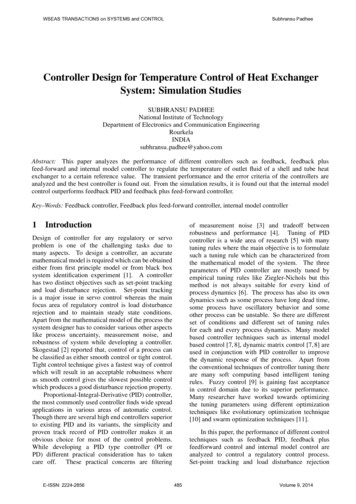
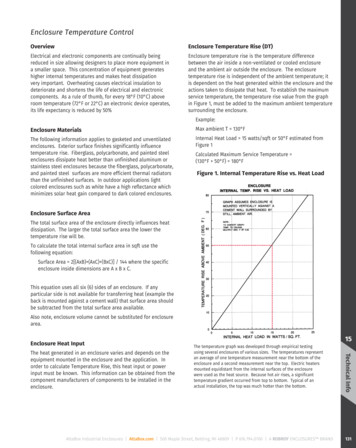
Enclosure Temperature ControlOverviewEnclosure Temperature Rise (DT)Electrical and electronic components are continually beingreduced in size allowing designers to place more equipment ina smaller space. This concentration of equipment generateshigher internal temperatures and makes heat dissipationvery important. Overheating causes electrical insulation todeteriorate and shortens the life of electrical and electroniccomponents. As a rule of thumb, for every 18 F (10 C) aboveroom temperature (72 F or 22 C) an electronic device operates,its life expectancy is reduced by 50%Enclosure temperature rise is the temperature differencebetween the air inside a non-ventilated or cooled enclosureand the ambient air outside the enclosure. The enclosuretemperature rise is independent of the ambient temperature; itis dependent on the heat generated within the enclosure and theactions taken to dissipate that heat. To establish the maximumservice temperature, the temperature rise value from the graphin Figure 1, must be added to the maximum ambient temperaturesurrounding the enclosure.Example:Enclosure MaterialsThe following information applies to gasketed and unventilatedenclosures. Exterior surface finishes significantly influencetemperature rise. Fiberglass, polycarbonate, and painted steelenclosures dissipate heat better than unfinished aluminum orstainless steel enclosures because the fiberglass, polycarbonate,and painted steel surfaces are more efficient thermal radiatorsthan the unfinished surfaces. In outdoor applications lightcolored enclosures such as white have a high reflectance whichminimizes solar heat gain compared to dark colored enclosures.Max ambient T 130 F Internal Heat Load 15 watts/sqft or 50 F estimated fromFigure 1 Calculated Maximum Service Temperature (130 F 50 F) 180 FFigure 1. Internal Temperature Rise vs. Heat LoadEnclosure Surface AreaThe total surface area of the enclosure directly influences heatdissipation. The larger the total surface area the lower thetemperature rise will be.To calculate the total internal surface area in sqft use thefollowing equation: Surface Area 2[(AxB) (AxC) (BxC)] / 144 where the specificenclosure inside dimensions are A x B x C.This equation uses all six (6) sides of an enclosure. If anyparticular side is not available for transferring heat (example theback is mounted against a cement wall) that surface area shouldbe subtracted from the total surface area available.Also note, enclosure volume cannot be substituted for enclosurearea.Enclosure Heat InputAttaBox Industrial Enclosures AttaBox.com 500 Maple Street, Belding, MI 48809 P 616.794.0700 A ROBROY ENCLOSURES BRAND15Technical InfoThe heat generated in an enclosure varies and depends on theequipment mounted in the enclosure and the application. Inorder to calculate Temperature Rise, this heat input or powerinput must be known. This information can be obtained from thecomponent manufacturers of components to be installed in theenclosure.The temperature graph was developed through empirical testingusing several enclosures of various sizes. The temperatures representan average of one temperature measurement near the bottom of theenclosure and a second measurement near the top. Electric heatersmounted equidistant from the internal surfaces of the enclosurewere used as the heat source. Because hot air rises, a significanttemperature gradient occurred from top to bottom. Typical of anactual installation, the top was much hotter than the bottom.131
Technical InformationEnclosure Temperature ControlInfluences of Heat TransferAir as an InsulatorConvection and thermal radiation are used most often todissipate heat from enclosures. Because polymers are a thermalinsulator, a common misconception exists that non-metallicenclosures operate at significantly higher temperatures thanmetal enclosures. To the contrary, performance data reflectthat enclosure material has little influence on the operatingtemperature and confirm that non-metallic and painted metallicenclosure function at nearly the same temperature with thesame internal heat load. Based on these observations materialthermal conductivity is not a major factor in determining heattransfer for an enclosure.If metals have much better thermal conductivity, why doesequipment in a polymer enclosure operate at nearly the sametemperature as in metal enclosures? The air confined withinthe enclosure has a K value of 0.017, almost 100 times less thanfiberglass specifically. The thermal resistance of the air andthe enclosure wall material are in series and must be added.Because air is a superior thermal insulator compared to eitherpolymer or steel, it is a predominant factor in establishing heatdissipation. This helps explain why equipment operates at thesame temperature regardless of which enclosure material is usedand also why environmental control systems heat or cool the airto control the internal temperature.Even though the thermal conductivity of a polymer is muchless than aluminum or steel, the heat transfer characteristic ofnon-metallic and metal enclosures are similar. Other factorssuch as the high thermal insulation of air contained within theenclosure along with the finish, color and total surface area ofthe enclosure have more influence on heat transfer than thermalconductivity. In general the finish and color of an enclosuremost affect the heat transfer capability, Indoor and in outdoorapplications.Thermal conductivity is commonly measured in BTU/hr/ft2/ F/in, the K Value. K units represent the quantity of heat, which canpass through one square foot of material in one hour for every Fin temperature difference across one inch of material thickness.Larger K values indicate better heat conductivity. The K valuefor fiberglass is 1.68; the K value for steel is 334; the K value foraluminum is 1050, and the K value for polycarbonate is 1.3.The heat transfer factor (Q) is measured in BTU/hr/ft2/ F orwatts/ft2/ F. For the analysis in this section the Q value used forsteel enclosures is 1.25 BTU/hr/ft2/ F (0.37 watts/ft2/ F); for nonmetallic enclosures the Q value is 0.62 BTU/hr/ft2/ F (0.2 watts/ft2/ F). The Q value for sheet metal enclosures will vary between1 BTU/hr/ft2/ F (0.29 watts/ft2/ F) and 5 BTU/hr/ft2/ F (1.46watts/ft2/ F), depending on the amount of enclosure insulation.Surface Area as a FactorAnother factor, which directly influences heat dissipation, issurface area. If the enclosure surface area is doubled with agiven internal heating load, the temperature rise will only be halfas great. It is important to remember that surface area is notnecessarily related to enclosure volume, i.e., an enclosure havingtwice the surface area does not always have twice the volume.Other Related IssuesCertain applications may require the walls of an enclosure toact as a heat sink. For example, it is not uncommon to locate ahigh power semiconductor on the wall of a metal enclosure todissipate heat. Non-metallic enclosures will not perform thisfunction efficiently because the polymer walls have negligiblethermal conductivity. In this application conduction is used todissipate the heat and a fiberglass enclosure will not functionthe same as a metal enclosure.15Technical Info132AttaBox Industrial Enclosures AttaBox.com 500 Maple Street, Belding, MI 48809 P 616.794.0700 A ROBROY ENCLOSURES BRAND
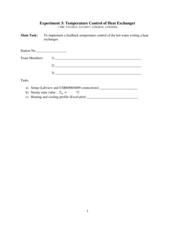
Enclosure Temperature ControlCalculating Temperature RiseEnclosure temperature rise can be approximated using thefollowing steps and calculations:1. Calculate the internal surface areaa. S ome common enclosure sizes and areas are alreadycalculated and can be found in Table 1.b. Using the Enclosure Surface Area formula on page 136.2. D etermine the Input Power by dividing the expected heat loadby the internal surface area.3. T hen using Figure 1, estimate the temperature rise by findingwhere the Internal Heat Load value intersects the line andreading the approximate temperature rise on the left verticalaxis of the graph. Note these are approximations, safety factors should beconsidered to minimize uncertainties.ExampleAn AH1816 enclosure contains a device that generates 120 watts,calculate the internal temperature rise.Solution1. Surface Area 9.1sqft (method for any size use calculation onpage 136 for Internal Surface Area).2. Internal Heat Load 120 watts / 9.1 sqft 13.1 Watts/sqft3. Using Figure 1, Input Power of 13.1 intersects the diagonal linecorresponds to a temperature rise of 42 F above ambient.15Technical InfoAttaBox Industrial Enclosures AttaBox.com 500 Maple Street, Belding, MI 48809 P 616.794.0700 A ROBROY ENCLOSURES BRAND133
Technical InformationEnclosure Temperature ControlAdditional Cooling MethodsSolutionWhen it has been determined that the heat load is too largefor an enclosure to dissipate by radiation and convection, thefollowing supplemental cooling methods are available:To determine the cubic feet per minute (CFM) required in astandard application, use the following equation (if the airdensity is significantly more that 0.075 lb. per cubic foot, a nonstandard application exists and this equation should not beused):Breather Vents and Louver VentsBreather Vents and Louver Vents are designed to remove heatfrom the enclosure by allowing natural air circulation around theheat source and exhausting the hot air through slots or louvers.This method is relatively inexpensive and has no operating cost;however, it can only be used to dissipate a limited amount ofheat and it is difficult to predict the temperature drop producedby a vent utilizing natural convection.Circulating FansIn larger sealed enclosures a fan can be used to circulate theair and reduce localized heat concentrations; however, theapplications are limited because a closed system fan onlyredistributes heat, it does not dissipate the heat generated bythe hot spot.Where an enclosure does not need to be sealed from the outsideenvironment, fans can be used to circulate air through anenclosure and dissipate the heat generated by power supplies,transformers and other heat producing equipment. Fans canprovide as much as 10 times the heat transfer rate of naturalconvection and radiation. Once the heat input in watts/ft2 isdetermined and temperature rise is established from Figure 1,the following equation can be used to calculate the fan flow rate:Fan Flow Rate (CFM) 3 .17 x Internal Heat Load (watts)/Temperature RiseFan Flow Rate (CFM) 3.17 x 300 watts/10 FFan Flow Rate (CFM) 95 CFMThis calculation is exact, but adding an additional 25% capacityto the CFM level is standard to provide a safety factor.1.25 x Fan Flow Rate (CFM) 1.25 x 95 CFM 119 CFMIf the air density is non-standard (significantly more than1.075 lb. per cubic foot), the following equation can be used tocalculate the fan capacity:Fan Flow Rate (CFM) x 0.075 lb. per cubic foot /Non-standard Air Density (lb. per cubic foot)Fans can be used to draw air through an enclosure insert,exhaust hot air from an enclosure or to draw cool air into anenclosure. An inlet fan offers the following advantages: Raises the internal pressure, which helps keep dust and dirtout of an unsealed or frequently open enclosure. More turbulent airflow improves heat transfer.Example Longer fan life with cooler incoming air.Equipment in an T363012 enclosure generates sufficient heatto require a fan, which will dissipate 300 watts. The maximumambient temperature in the application environment is 115 F. Ifthe temperature of the other contents in the enclosure cannotexceed 125 F, what size is required?15The allowable temperature rise is 125 F - 115 F 10 F. Theapplication requires dissipation of 300 watts.Technical Info134AttaBox Industrial Enclosures AttaBox.com 500 Maple Street, Belding, MI 48809 P 616.794.0700 A ROBROY ENCLOSURES BRAND
Enclosure Temperature ControlThe following considerations are important in locating a fan:Example A void placing transformers, power supplies or other heatgenerating devices in front of the fan. Although this cools thedevice, it increases the heat load on other devices within theenclosure. It is best to place these devices near the exhaustoutlet.If the internal heat load is 1000 watts in an T603612 Fiberglassenclosure, what is the minimum cooling capacity for the heatexchanger unit? The Maximum ambient temperature is 130 F andthe internal equipment will malfunction if the internal enclosuretemperature exceeds 105 F. T o achieve maximum cooling, the inlet and outlet should beseparated by the maximum distance. If the outlet and inletare adjacent to each other, the hot outlet air will be drawn intothe inlet and cooling efficiency will be reduced. In general theinlet should be at the bottom of the enclosure and the outletat the top. F ans should not be used or located in areas where the airflowis restricted. A plenum is recommended to accelerate airvelocity and improve fan performance. A plenum is particularlyhelpful when a filter is used where airborne contaminants area problem. T he air outlet area should at least equal the inlet area. Forbest results the exhaust opening should be 1.5 times the areaof the fan opening. A ir is less dense at high altitudes. For this reason airflowshould be increased in high altitude applications. All fans used in parallel should be identical.Heat Exchangers - CoolingHeat exchangers are a good option when precise control ofheat and humidity are not required and the heat transferrequirements are significant. The required heat exchangercapacity can be calculated using the formula,Heat ExchangerInternal Heat Load/DT 0.22 xCapacity (watts/ F) Enclosure Surface Area,Where DT Temperature Rise.SolutionInternal Heat Load 1000 wattsMaximum Temperature Differential Ti - To 105 F130 F -25 F [25 F], use Absolute Value.Enclosure Surface Area 48.48 ft2Heat Exchanger Capacity 1000 watts/(25 F) - 0.22 x 48.48 ft2 29.33 watts/ FIn this example the surfa
Enclosure temperature rise can be approximated using the following steps and calculations: 1. Calculate the internal surface area a. Some common enclosure sizes and areas are already calculated and can be found in Table 1. b. Using the Enclosure Surface Area formula on page 136. 2. Determine the Input Power by dividing the expected heat loadFile Size: 961KBPage Count: 7