Transcription
Variable Volume Chilled Water PumpingSystem ControlsDave Hacker – Engineering ManagerKyle Schroeder, PE – Sales Engineer
Outline Introduction Chilled Water Pumping SystemsConfigurations / Control Strategies– Primary – Secondary Pumping– Variable Primary Pumping Demonstration / Live Web Graphics Discussion and Questions
Local Service and SupportInnovative Energy Solutions 45 year record of successful project installations– Hundreds of local DDC installations On-staff engineers, technicians– Factory-trained 24 hour 7 day on-call service for Temperature Controlsand Full HVAC Mechanical Service Service agreements Comprehensive local parts stock Local training Over 250 years HVAC / Controls experience on staff
Evolution of Pumping sVFDsrellihCwolFelbairaV1990s2000s3-way valvesIn nova Primary / SectiononndaryBypass Valves
Basic Chilled Water Pumping System
Basic Chilled Water Pumping System Single Chiller, Single Constant Speed Pump 3-way valves for all Chilled Water Coils () maintains constant flow. Control strategy: Enable chilled water pumpwhen outside air temperature is abovesetpoint and at least 1 chilled water coilcontrol valve is open to coil. Enable chillerafter flow is proven. Chiller operates tomaintain leaving chilled water temperature atsetpoint. Coil valves modulate to maintaincomfortable space conditions.or evenmore basic – no valves – full flow
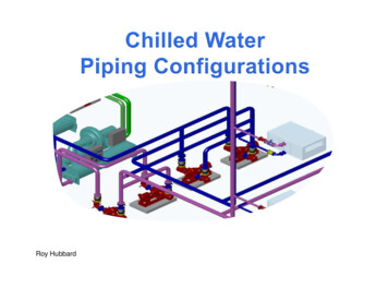
Basic Primary / Secondary Chilled WaterPumping System with a 3-way valve
Basic Primary / Secondary Chilled WaterPumping System Single Chiller, Single Constant Speed Primary Pump, bypass loopwith no valve, Variable Speed Secondary Pump.The primary pump pumps water through the chiller. The secondarypump pulls water from the primary system and pumps it to the coils.Add a Water Differential Pressure Transmitter near the end of thepiping run (in an accessible location).VFDs and pumps have minimum recommended operating speeds,typically about 20%. Use 3-way valves for 1 or more coils to ensurethat there is always this amount of water flowing in the secondaryloop. My recommendation is to use 3-way valves at units that areexpected to have full occupancy for the most hours and not atGymnasium or other units that serve areas where significantoperating time is at less than full occupancy (partial / low load areas).Control strategy: Enable both primary and secondary chilled waterpumps when outside air temperature is above setpoint and at least 1chilled water coil control valve is open to coil. Modulate (vary) thespeed of the secondary pump VFD to maintain a constant differentialpressure. Enable chiller after flow is proven. Chiller operates tomaintain leaving chilled water temperature at setpoint. Coil valvesmodulate to maintain comfortable space conditions.
Primary / Secondary Chilled WaterPumping System with Bypass Valve
Primary / Secondary Chilled WaterPumping System with Bypass Valve Single Chiller, Single Constant Speed Primary Pump, bypass loop,Variable Speed Secondary Pump. 2-way valves at all chilled watercoils and secondary bypass loop with 2-way valve.The primary pump pumps water through the chiller. The secondarypump pulls water from the primary system and pumps it to the coils.Water Differential Pressure Transmitter near the end of the piping run.VFDs and pumps have minimum recommended operating speeds,typically about 20%. Use a bypass valve in the secondary loop. Myrecommendation is to locate the valve in the chiller mechanical room.Control strategy: Enable both primary and secondary chilled waterpumps when outside air temperature is above setpoint and at least 1chilled water coil control valve is open to coil. Modulate (vary) thespeed of the secondary pump VFD to maintain a constant differentialpressure. Enable chiller after flow is proven. Chiller operates tomaintain leaving chilled water temperature at setpoint. Coil valvesmodulate to maintain comfortable space conditions.When secondary pump speed is at minimum setting, bypass valvemodulates to maintain secondary loop differential pressure. Afterpressure drops below setpoint and bypass valve is closed, pumpspeed will vary (increase initially) to maintain differential pressure.OR – modulate bypass valve inversely to coil valves (be careful).
Primary / Secondary Chilled WaterPumping System with Lead / Lag
Primary / Secondary Chilled WaterPumping System with Lead / Lag Multiple Chillers, Multiple Constant Speed Primary Pumps, bypass loop,Multiple Variable Speed Secondary Pumps. 2-way valves at all chilled watercoils and secondary bypass loop with 2-way valve.Each primary pump pumps water through a chiller. These can be piped soeither pump can work with either chiller if isolation valves are used at eachchiller or with dedicated primary pumps for each chiller. The secondary pumpspulls water from the primary system and pumps it to the coils.Control strategy: Open 1 chillers isolation valve, enable one primary and onesecondary chilled water pump when outside air temperature is above setpointand at least 1 chilled water coil control valve is open to coil. Modulate (vary)the speed of the secondary pump VFD to maintain a constant differentialpressure. Enable chiller after flow is proven. Chiller operates to maintainleaving chilled water temperature at setpoint. Coil valves modulate to maintaincomfortable space conditions.When lead secondary pump speed is at minimum setting, bypass valvemodulates to maintain secondary loop differential pressure. After pressuredrops below setpoint and bypass valve is closed, pump speed will vary(increase initially) to maintain differential pressure. When pump speed isabove 50%, enable the lag secondary chilled water pump, vary both until theirspeed drops below 20%, then stop the lag pump. Bypass valve should beclosed whenever 2 secondary pumps are operating.Only enable the lag primary pump after the lag chiller’s isolation valve is open,and the lead chiller is not able to maintain the leaving water temperaturesetpoint. Generally, It is best to max out 1 chiller rather than to run 2 partiallyloaded chillers.
Primary / Secondary Chilled WaterPumping System with Lead / Lag withenough 3-way valves and no bypass
Variable Primary Chilled Water PumpingSystem with some 3-way valves
Variable Primary Chilled Water PumpingSystem with some 3-way valves Single Chiller, Single Variable Speed Pump3-way valves for some Chilled Water Coils to maintainminimum flow required for chiller. Chillers have minimum flowsthat are typically higher than their associated VFDs andpumps.The single primary pump pumps water through the chiller andto the coils.Water Differential Pressure Transmitter near the end of thepiping run varies the speed of the VFD.Control strategy: Enable the primary chilled water pump whenoutside air temperature is above setpoint and at least 1 chilledwater coil control valve is open to coil. Modulate (vary) thespeed of the pump VFD to maintain a constant differentialpressure. Enable chiller after flow is proven. Chiller operatesto maintain leaving chilled water temperature at setpoint. Coilvalves modulate to maintain comfortable space conditions.
Variable Primary Chilled Water PumpingSystem with Bypass Valve
Variable Primary Chilled Water PumpingSystem with Bypass Valve Single Chiller, Single Variable Speed Pump. 2-way valves at allchilled water coils and bypass loop with 2-way valveThe single primary pump pumps water through the chiller and to thecoils.Water Differential Pressure Transmitter near the end of the piping runvaries the speed of the VFD and modulates bypass valve.Modulate bypass valve when pump reaches minimum speed.Control strategy: Enable primary chilled water pump when outside airtemperature is above setpoint and at least 1 chilled water coil controlvalve is open to coil. Modulate (vary) the speed of the pump VFD tomaintain a constant differential pressure. Enable chiller after flow isproven. Chiller operates to maintain leaving chilled water temperatureat setpoint. Coil valves modulate to maintain comfortable spaceconditions.When pump speed is at chiller required minimum setting, bypassvalve modulates to maintain secondary loop differential pressure.After pressure drops below setpoint and bypass valve is closed, pumpspeed will vary (increase initially) to maintain differential pressure.
Variable Primary Chilled Water PumpingSystem with Bypass Valve & Flow Meter
Variable Primary Chilled Water PumpingSystem with Bypass Valve & Flow Meter Single Chiller, Single Variable Speed Pump. 2-way valves at allchilled water coils and bypass loop with 2-way valveThe single primary pump pumps water through the chiller and to thecoils.Water Differential Pressure Transmitter near the end of the piping runvaries the speed of the VFD. The flow meter is used to modulate thebypass valve to maintain minimum chiller flow requirement.Modulate bypass valve when flow meter reaches minimum flowsetting.Control strategy: Enable primary chilled water pump when outside airtemperature is above setpoint and at least 1 chilled water coil controlvalve is open to coil. Modulate (vary) the speed of the pump VFD tomaintain a constant differential pressure. Enable chiller after flow isproven. Chiller operates to maintain leaving chilled water temperatureat setpoint. Coil valves modulate to maintain comfortable spaceconditions.Modulate bypass valve to maintain chilled water flow. Pump speedwill continue to vary to maintain differential pressure.
Variable Primary Chilled Water PumpingSystem with Bypass Valve & chiller DPT
Variable Primary Chilled Water PumpingSystem with Bypass Valve & chiller DPT Single Chiller, Single Variable Speed Pump. 2-way valves at allchilled water coils and bypass loop with 2-way valveThe single primary pump pumps water through the chiller and to thecoils.Water Differential Pressure Transmitter near the end of the piping runvaries the speed of the VFD. The Water Differential PressureTransmitter near the chiller is used to modulate the bypass valve tomaintain minimum chiller flow requirement based on differentialpressure setpoint.Modulate bypass valve when chiller evaporator barrel differentialpressure reaches minimum flow setting.Control strategy: Enable primary chilled water pump when outside airtemperature is above setpoint and at least 1 chilled water coil controlvalve is open to coil. Modulate (vary) the speed of the pump VFD tomaintain a constant differential pressure. Enable chiller after flow isproven. Chiller operates to maintain leaving chilled water temperatureat setpoint. Coil valves modulate to maintain comfortable spaceconditions.Modulate bypass valve to maintain chiller evaporator barrel differentialpressure. After pressure rises above setpoint and bypass valve isclosed, pump speed will continue to vary to maintain differentialpressure.
Variable Primary Chilled Water PumpingSystem with Lead / Lag
Variable Primary Chilled Water PumpingSystem with Lead / Lag Multiple Chillers, Multiple Variable Speed Primary Pumps, 2-way valves at allchilled water coils and a bypass loop with a 2-way valve.Each primary pump pumps water through a chiller and to the coils. These canbe piped so either pump can work with either chiller if isolation valves are usedat each chiller or with dedicated primary pumps for each chiller.Control strategy: Open 1 chiller’s isolation valve, enable one primary chilledwater pump when outside air temperature is above setpoint and at least 1chilled water coil control valve is open to coil. Modulate (vary) the speed of thepump VFD to maintain a constant differential pressure. Enable chiller afterflow is proven. Chiller operates to maintain leaving chilled water temperatureat setpoint. Coil valves modulate to maintain comfortable space conditions.Bypass valve modulates to maintain minimum chiller flow through eachoperating chiller.When lead pump speed is above 50%, enable the lag chilled water pump, varyboth until their speed drops below 20%, then stop the lag pump.When the 2nd chiller is needed – which can be determined by adding amatched pair of temperature sensors for each chiller to the associated flowmeter to calculate the BTUs (or Tons), lock both variable speed pumps at 70%(Adj), wait 30 Sec, open the bypass valve to 30% (Adj), then after another 30Sec delay, allow the isolation valve on the lag chiller open and start the lagchiller. Hold the pumps at a minimum of 70% and the bypass valve at a minposition of 30% Open for 15 Min (Adj) to allow 2nd chiller to get loadedup. Once the 15 minutes have expired, return system to normal control.
Flow Meter Selection and InstallationGuidelines Turbine Meters vs. Paddle Wheel. See Accuracy Statement. See Installation Guide. Recommend minimum 25 pipe diameters of straight pipe. 80%upstream and 20% downstream. There are slightly more expensive dual turbine flow metersavailable if there is less than 25 pipe diameters of straight pipe.
Flow Meter Selection and InstallationGuidelines Turbine Meters vs. Paddle Wheel. FeatureInsertion Turbine (O)ReliabilityExcellent – No Fault WarrantyAccuracyExcellent – 1% of RATE !NIST Traceable Volume CalibrationYesTurndownExcellentBearing LifeExcellentInstall & Remove Under PressureYes Paddle Wheel Turbine Meter. Turbine Meter. Paddle Wheel.Paddle Wheel (K).Fair to Poor – Standard Warranty1% of FULL SCALENoFair to PoorFair to PoorNo
Water Differential Pressure Sensor andInstallation Guidelines Dual Pressure Sensor type. Improved Overpressure Tolerance. Basic shutoff valves instead of 3-valve bypass. LCD display.
Demonstrations and Questions?
Questions from Presentation & AnswersQ: What is the price difference between a flow meter and a Differential Pressure Transmitter?A: Cost of instrumentation is about 500 more for flow meter.Q: What type of bypass valves are recommended
Chiller operates to maintain leaving chilled water temperature at setpoint. Coil valves modulate to maintain comfortable space conditions. Modulate bypass valve to maintain chiller evaporator barrel differential pressure. After pressure rises above setpoint and bypass valve is closed, pump speed will continue to vary to maintain differential pressure. Variable Primary Chilled Water Pumping .