Transcription
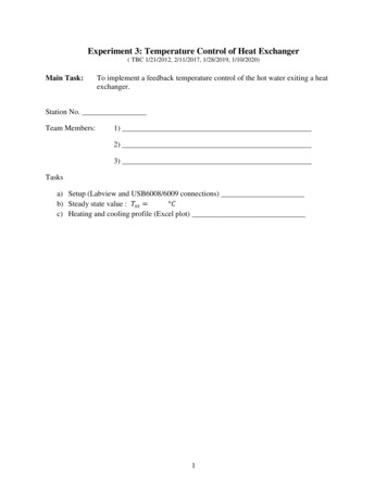
Experiment 3: Temperature Control of Heat Exchanger( TBC 1/21/2012, 2/11/2017, 1/28/2019, 1/10/2020)Main Task:To implement a feedback temperature control of the hot water exiting a heatexchanger.Station No.Team Members:1)2)3)Tasksa) Setup (Labview and USB6008/6009 connections)b) Steady state value : 𝑇𝑠𝑠 𝐶c) Heating and cooling profile (Excel plot)1
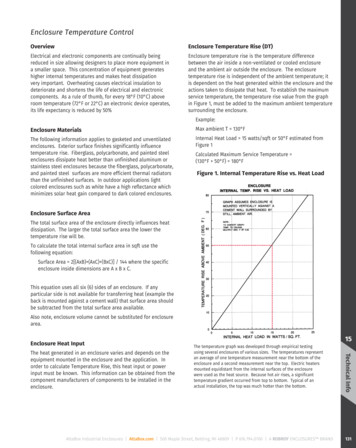
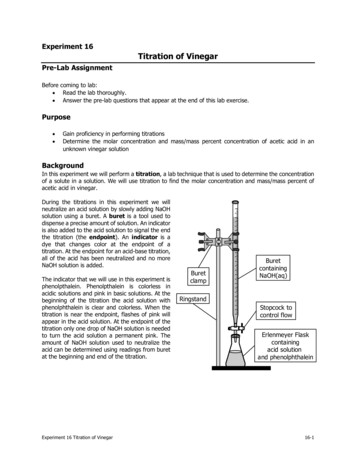
I.Feedback Control SetupA. HardwareThe signal 𝑢 is a voltage ranging from 0 to 5 volts, whose value will be determined usingthe proportional control law given by𝑢 𝑢0 𝐾𝑐 (𝑇𝑠𝑒𝑡 𝑇𝑚 )where 𝑢0 is the bias value based on the nominal steady state performance, 𝐾𝑐 is theproportional gain, 𝑇𝑠𝑒𝑡 is the set point temperature and 𝑇𝑚 is the measured value of thetemperature of the heated water. The control scheme is shown in the block signal diagramshown in Figure 1 below. In the figure, the actuator includes the transducer and the controlvalve.Tset -eControlLawTmControl zvalve(Actuator)uRTD (Sensor)HeatExchangerTTFigure 1. Feedback loop.The NI USB6008/6009 supplies 5v from the digital side. Voltage signal from the RTD areinput to the USB device via the AI0 port, while voltage signal from the laptop will be sentto transducer via the AO0 port.Note: connect the positive ( ) port of the transducer to AO0 port of USB6008 and connectthe negative (-) port of the transducer to the GND port. of USB6008.B. Labview Program (Note: you need to connect the DAQ device and already have thehardware driver installed before you procede.)2
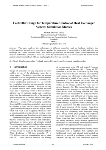
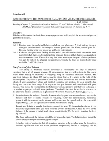
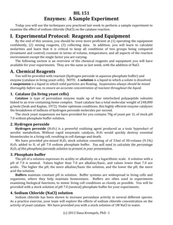
Figure 2. Labview block diagram.Figure 3. Labview front panel.3
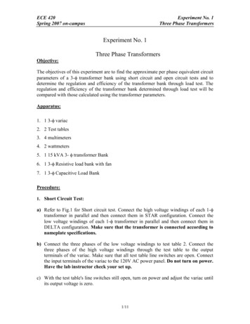
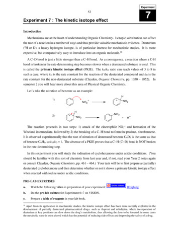
1. Start with same set-up and blocks as in Lab 2 including the RTD blocks.2. Create the control law blocks:a. Import [Express] [Arithmetic and Comparison] [Formula] block,then type in the following formula:max(0,min(5,u0 Kc*(Tset-T)))(Note: this is to keep the value of 𝑢 within 0 and 5 volts, otherwise anerror will occur during the run if 𝑢 is allowed to have negative or valuesgreater than 5)b. Right-click on each of the inputs, then select [Create] [Control].c. Import [Express] [Output] [DAQ Assist] block. Select [GenerateSignals] [Analog output] [Voltage]. Select port AO0. Then set maxto 5 and min to 0.(Leave the setting on [On demand])d. Connect wires as shown in Figure 2. You will need to including a mergesignals block: [Express] [Signal Manipulation] [Merge Signals]3. Create the “write to measurement” blocks ( refer to steps in Lab 1).II.Heat Exchanger Startup( based on procedure for heat transfer coefficient experiment found in CM3215 developed by F.Morrison, revised for CM3310 by T. Co)CAUTION: Always wear insulated gloves when adjusting the steam valve, when touchinguninsulated piping or when handling condensate. The equipment may be hot at thebeginning of lab.If the TA has not done it yet, connect the transducer to the compressed air supply and to thesteam valve. (see Figure 4.)Pressure RegulatorSteam ValveTo Controller Unit Compressed airsupplyE/PTransducer-Figure 4. Connecting the transducer to the air supply and steam valve.4
Begin water flow in the loop as follows:1. Start water flow through the ½” pipe as follows. Make sure that tank T-02 is empty andclean. Close the drain valve (DV-2).2. Open water valve WV-10 and fill T-02 with water. Once the tank is filled, the watercontrol float valve will shut-off water flow. The water control float valve keeps waterlevel constant at a set point.3. Make sure valves WV-1, WV-2, and WV-3 as well as the needle valve WV-5 are allclosed.4. Turn on pump P-01.a) Turn power on Make sure display is on “d001” After a few seconds “0.0” should appear and “Hz” led is litb) Use “up” and “down” arrow to make sure speed is set at 25.0 Hzc) Push [Green] button to start pump5. Direct the water through the ½” pipe by opening valve WV-1. Turn three-way valveWV-4 knob to direct the water flow through rotameter FI-01. Make sure that valves WV6 and WV-7 are closed. Adjust three-way valve WV-8 to direct water to the heatexchanger E-01. Turn three-way valve WV-9 knob to direct water to T-02.6. Fix the water flow rate to 15% on FI-01 by using needle valve WV-5.Begin flow of steam through the outer jacket of the heat exchanger as follows:7. Position three-way valve SV-3 to direct flow through the steam trap 2.8. Open the main steam valve SV-1.Drain condensate from the line as follows:9. Check with the TA to see if this step has been done; if not, using insulated gloves,position the black rubber drain hose located downstream of SV-2 in a Styrofoam bucket.One team member should stabilize the bucket and hose.10. Using insulated gloves, open SV-2 slowly to drain all of the line condensate into thebucket. Close SV-2 when steam begins to come out of the hose. Dispose of thecondensate in a floor drain – do not use the sink drain. Clean up any water spills withpaper towels.11. Return the rubber hose to common drain.Start steam flow:12. Open DV-1. Turn three-way valve WV-9 knob to direct water to T-01. Verify that thepump is on and that water is circulating through the inside of the heat exchanger. Do notrecirculate water back to tank T-02.13. Open main air valve AV-1 and set the control valve FV-06 to 18 psig.III. Control Experiment5
1. Set 𝑢0 4.0 𝑣𝑜𝑙𝑡𝑠 and 𝐾𝑐 0 (this sets the control law to be a manual mode) and notewhat the steady state temperature is, 𝑇𝑠𝑠1 .2. After steady state has been achieved, start collecting data to a file by clicking the “Startdata” button.3. Change the setpoint to 𝑇𝑠𝑒𝑡 𝑇𝑠𝑠1 5, then change the proportional gain to 𝐾𝑐 0.5.4. After a new steady state has been achieved, change the set point to 𝑇𝑠𝑒𝑡 𝑇𝑠𝑠1 10.5. Wait until the new steady state, stop the program.6. Plot your data on Excel.6
IV.Heat Exchanger ShutdownProcedure( based on procedure for heat transfer coefficient experiment found in CM3215 developed by F.Morrison, revised for CM3310 by T. Co)1.2.3.4.5.Set the air pressure regulator to 0 psig using the pressure regulator.Close the main air valve AV-1.Close main steam valve SV-1.Return all drain hoses to the common drain.Allow the cold water to circulate through the loop to cool the heat exchanger for at least 3minutes. Stop when the piping at the cold-water exit of the heat exchanger is cool to thetouch.6. Close valves WV-1 and needle valve WV-5.7. Turn off pump P-01.a. Push [RED] buttonb. Switch power off8. Close main water valve WV-10.9. Position three-way valve WV-9 to direct flow to Tank T-02.10. Drain all tanks.11. Dry off any wet surfaces with paper towels. Turn off all the electronic devices andproperly store them.12. (If you are in the last session of the day, detach the transducer from the compressed airline and the steam valve then reconnect air line directly to steam valve).7
IV. Heat Exchanger ShutdownProcedure ( based on procedure for heat transfer coefficient experiment found in CM3215 developed by F. Morrison, revised for CM3310 by