Transcription
SAND2007-6940CProceedings of the 15th International Symposium on thePackaging and Transportation of Radioactive MaterialsPATRAM 2007October 21-26, 2007, Miami, Florida, USASTRAIN-BASED ACCEPTANCE CRITERIA FOR SECTION III OF THE ASMEBOILER AND PRESSURE VESSEL CODEDoug AmmermanSandia National Laboratories*Gordon BjorkmanU.S. Nuclear Regulatory CommissionABSTRACTModern finite element codes used in the design of nuclear material transportation and storagecasks can readily calculate the response of the packages beyond the elastic regime. Thesepackages are designed to protect workers, the public, and the environment from the harmfuleffects of the transported radioactive material following a sequence of hypothetical accidentconditions. Hypothetical accidents considered for transport packages include a 9-meter free droponto an essentially unyielding target and a 1-meter free fall onto a 30-cm diameter puncturespike. For storage casks, accident conditions can include drops, tip-over, and aircraft impact. Allof these accident events are energy-limited rather than load-limited, as is typically the case forboilers and pressure vessels. Therefore, it makes sense to have analysis acceptance criteria thatare more closely related to absorbed energy than to applied load. Strain-based acceptance criteriaare the best way to meet this objective.As cask vendors’ ability to perform non-linear impact analysis has improved, the need for acode-based method to interpret the results of this type of analysis has increased. The ASMESection III Working Group on Design of Division 3 Containments is working with Section IIIWorking Group Design Methodology to develop strain based acceptance criteria to use withinthe ASME Code for energy limited events. This paper will briefly discuss the efforts within theASME, detail the advantages of using strain-based criteria, discuss the problem areas associatedwith establishing strain-based criteria, and provide insights into inelastic analyses as applied toradioactive material transportation and storage casks in general. The views expressed representthose of the authors and not necessarily those of their respective organizations or the ASME.INTRODUCTIONThe U.S. NRC has a long history of assuring the safety of the public from the potential hazardsassociated with the transportation of radioactive material. For most of this history, the design ofthe packages used to transport this material has been based upon the ASME Boiler and PressureVessel Code[1] and guidance has been provided by U.S. NRC Regulatory Guide 7.6 [2]. For thepast decade, the section of the Code that is most relevant to the design has been Section III,Division 3. This section of the Code is based upon the concept of stress intensity, which is twicethe maximum shear stress. The allowable stress intensities vary according to loading case andSandia is a multi-program laboratory operated by Sandia Corporation, a Lockheed Martin Company, for the UnitedStates Department of Energy under contract DE-AC04-AL85000.1
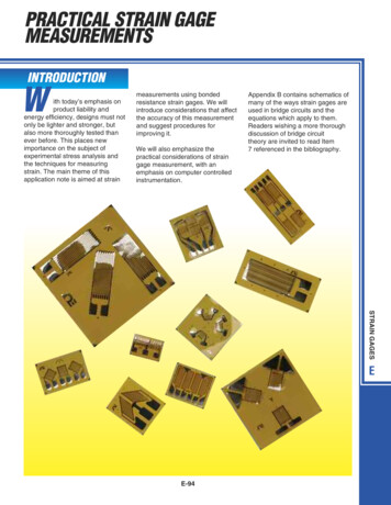
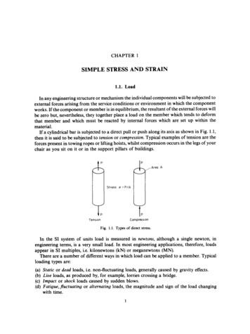
type of stress. For some of these, the allowable stress intensity is larger than the yield stress ofthe material, a tacit approval for a limited amount of plasticity. This approach was necessarywhen stresses were determined with hand calculations and was still beneficial during the earlydays of finite element analyses. As finite element calculations became more detailed, it hasbecome possible to determine the stress state at any point in the package and the associatedstrains. Since the Code has allowed limited plasticity, modern package designers would prefer touse inelastic analysis techniques to calculate the stresses and strains that result from the requiredloading conditions. There are two ways to implement inelastic analysis: continue using stressbased acceptance criteria, or; develop strain-based acceptance criteria. Other parts of the Code(Section III, Division 1, Appendix F) allow the use of inelastic analysis, but these sections arenot approved for the design of transportation packages except on a case-by-case basis. Theacceptance criteria in Appendix F are stress-based, and the allowable stresses are a function ofyield stress and/or ultimate stress. The major focus of this paper will be strain-based acceptancecriteria, but some reference to the stress-based acceptance criteria of Appendix F will beincluded.MATERIAL BEHAVIORThe ductile materials that are used for structural parts of radioactive material packages exhibitthe capability of absorbing large amounts of energy via plastic deformation. Because the accidentconditions that generally govern the designs, such as the 9-meter drop test and the 1-meterpuncture drop, are energy-limited events instead of load-limited events, maximum safety isassured by using materials with large capacity to absorb energy rather than by materials withmaximum strength. Figure 1 shows the engineering and true stress strain curves of two materials,one an austenitic stainless steel and the other a high-strength carbon steel. The engineeringstress-strain curves are shown because these are the curves that have been traditionally used todevelop the allowable stresses in the ASME Code. The true stress-strain curves are shownbecause modern finite element programs calculate stresses and strains based on the currentgeometry instead of the initial geometry and therefore compute true stresses and strains. Thedesign stress intensity (Sm) of the high-strength steel is larger than that for the austenitic stainlesssteel, but the area under the stress-strain curve up to the point of maximum load in a tensile test(directly proportional to the amount of energy that can be absorbed) is larger for the austeniticstainless steel. The point of maximum load in a tensile test is also the limit of uniformelongation, beyond this point there is localization of strain and the tensile test specimen becomesunstable. Although there is considerable amount of energy absorption capacity beyond this point,the onset of instability is generally avoided, and it is prudent in design to not use this reservecapacity. Another important factor to notice from the stress-strain curves in Figure 1 is that in theregion of maximum load from the tensile test, both the engineering and true curves are increasingin strain much faster than they are increasing in stress. This implies that inaccuracies incalculated strain are much less important than inaccuracies in calculated stress.For implementation of inelastic analysis in finite element codes a representation of the stressstrain curve is needed. This representation can be either continuous or piece-wise linear. The truestress-strain curve shown for 304L stainless steel in Figure 1 can be represented by the powerlaw equation:a ay Asn,where:Gy is the yield strength (more accurately the limit of proportionality) and is equal to 192 MPa;A is the hardening constant and is equal to 1323 MPa, determined from curve fitting to test data;and2
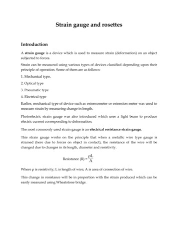
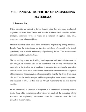
n is the hardening exponent, which is equal to 0.74819, also determined from curve fitting.For Code approved analyses a method must be developed to define this curve for any materialthat is used. The effect of both temperature and strain rate on the curve must also be considered.In the analysis community the preferred method for obtaining material data is to conduct anactual tensile test at the strain rate and temperature of interest. In the design community this isnot possible, because the material to be included in the article being designed has not yet beendelivered. ASTM material specifications do not specify stress-strain curves, and there can beconsiderable variability within a material type.304L TRUE304L ENG.HSS TRUEHSS ENG.r 8ooX304L Max. Load TRUE 304L Max. Load ENG.XHSS Max. Load TRUE HSS Max. Load ENG.StrainFigure 1 - Stress-strain curves for an austenitic stainless steel and a high strength carbonsteelA complication to the development of strain-based acceptance criteria is the relationship betweenstrain to failure and stress state. The familiar nd (3) averageor localized (through the thickness) plus peak (surface) strains.COMPARISON OF ACCEPTANCE CRITERIAThe goal of the Code for the design of radioactive material transportation packages is the samewhatever acceptance criteria are used - to assure the package can perform its intended functionof containing the radioactive contents. It is expected that the design of packages will not changesignificantly with any change of acceptance criteria, but rather that the acceptance criteria willmake it easier to demonstrate compliance with the intent of the regulations. For this reason, it isinstructive to compare several possible acceptance criteria. The first of these must be thecurrently approved elastic analysis method. For this comparison we will consider one loadingcase of the package, simple beam bending of the overall cross-section. In this example we willconsider the 22,500 kg package shown in Figure 3 constructed of Type 304 stainless steelsubjected to a side impact of 200G. This loading is somewhat typical for that resulting from aside drop. Material properties for the stainless steel (room temperature values) are given inTable 1. For membrane stress the allowable is the lesser of 2.4 Sm or 0.7 Su. For this material 2.4Sm governs and the allowable stress is 331 MPa. For membrane plus bending stress the allowablestress is the lesser of 3.6 Sm or Su. For this material the 3.6 Sm governs and the allowable stress is496 MPa. Figure 4 shows several possible stress-strain curves to use for the inelastic analysis ofthis problem. The dashed curves are true-stress vs. true-strain and the solid curves areengineering-stress vs. engineering-strain. The top curve is the true-stress vs. true-strain derivedfrom an actual tension test. The other curves are scaled versions of this curve or the hi-linearrepresentation of it using yield and the point of maximum load. Also shown on the graph are fourlimit states based upon 0.7SU: the lowest is from using the Code value for Su as an engineeringstress, the next up is 0.7Smax from the test-based engineering stress-strain curve, and finally thetwo true stress limits that correspond to the engineering stresses, based on their respectiveengineering stress-strain curves.100 mm ----- 800 mm ------------------------------------------------- 14000 mmFigure 3 - Example cask for comparing acceptance criteria5
Table 1 - Material properties for SA 24( Type 304 stainless steelPropertyValueUltimate strength, S„ [5]Yield strength, Sv [5]Design stress intensity, Sm [1]2.4 Sm3.6 Sm0.7 SuMinimum % elongation [5]515 MPa205 MPa138 MPa331 MPa496 MPa361 MPa40— —True Tensile TestEng. Tensile Test— Scaled TrueScaled Eng.— —True bi-linear------ Bi-linear— True Code UltimateCode Ultimate— - - 0.7Su— - - 0.7Smax— - True at 0.7Su—— - True at OJSmaxStrainFigure 4 - Stress-strain curves for 304 stainless steelFor simple beam bending the maximum membrane stress using elastic analysis is 331 MPa. Thisis exactly the allowable stress. The maximum membrane plus bending stress is 378 MPa,compared to an allowable of 496 MPa. For illustration, the problem was constructed so thedesign would have no margin of safety against the design allowable stress. If we assume thepackage behaves as a Bernoulli beam (plane sections remain plane) for the inelastic analysis weobtain a maximum membrane stress of 306 MPa, a maximum membrane plus bending stress of318 MPa, and a maximum engineering strain of 5.3%. The Appendix F allowable stress(currently this analysis technique is not accepted in Section III, Division 3, but is beingconsidered by the ASME to be included in Division 3) is 361 MPa (0.7 S„) for membrane stress,giving a design margin of 15%, and 464 MPa (0.9 S„) for membrane plus bending stress. Themaximum strain is 13% of the percent elongation.6
To further illustrate the difference in package designs that come from the use of inelastic analysisconsider the increase in deceleration on the package so the inelastic analysis stress is at theallowable stress levels from Appendix F. The maximum membrane stress resulting from a 234Gdeceleration would be 361 MPa, the allowable membrane stress. Alternatively, if the thickness ofthe wall of the package is reduced to increase the inelastic analysis computed stress. keeping theoriginal 200G deceleration, a wall thickness of 81 mm results in a maximum membrane stress of361 MPa. In both of these adjusted designs the maximum strain is less than 9.5%, still wellbelow the minimum percent elongation.DISCUSSIONModern finite element analysis methods allow for the accurate depiction of the stress and strainstate in the structural components of radioactive material transportation packages. However, thecurrent design allowable stresses are not well aligned with this new capability. The purpose ofanalysis acceptance criteria is to prevent against rupture of the containment boundary. Thispurpose can be more readily accomplished with strain-based acceptance criteria. There are twoareas of difficulty in establishing new acceptance criteria: 1) determining the appropriate limits,and 2) developing a method to determine if those limits have been met.The first of these is primarily a material issue, and a new series of material tests (similar to thoseused to determine the current limits based upon Sm and Su) may be required to establish theselimits. For example, strain-based acceptance criteria should be tied to the uniform elongationstrain (the strain at the point of maximum load in a tensile test), but this value is typically notreported. In the example above the material specification minimum percent elongation was usedas a surrogate for this value. Actual tensile tests for Type 304 stainless steel typically showmaximum load occurring at an engineering strain of about 65%. This corresponds to a true strainof 50%. The problem of strain limits may be alleviated by choosing an allowable strain that issufficiently low that it is below the failure strain independent of stress state or how the materialstrain-to-failure is determined. However, the Code should allow the designer to choose a moreaccurate method of determining the strain at material failure and then have the design allowablestrain as a higher percentage of the failure strain. To generate discussion, possible limits are 15%of the true strain at the point of maximum load as determined from a tensile test (uniformelongation strain) if stress triaxiallity is not considered in the analysis and 70% of the failurestrain as a function of stress triaxiallity if it is considered.The second area is determining the value to compare against the acceptance criteria. Moderninelastic analysis finite element codes produce outputs in terms of equivalent plastic strain,which is a scalar representation of the magnitude of the strain tensor. The post-processingsoftware can display the value as a contour plot or fringe plot. The analyst can easily determinethe maximum strain in any material or part. However, some amount of judgment is needed todetermine if the plastic strain is the result of membrane action, membrane plus bending action, ora localized strain due to a discontinuity. If the designer chooses to use the failure strainconsidering stress triaxiallity a mapping of strain vs. stress triaxiallity is required. The off-theshelf versions of current finite element analysis codes do not compute stress triaxiality and theanalyst is forced to create a user subroutine for this calculation.EXTENSIONThe previous discussion and the current ASME Problem Statement are focused on the analysesassociated with the 9-meter regulatory impact test. However, the ASME Problem Statement doessuggest that regions of the containment remote from the impact point can be evaluated for the7
loads applied during a puncture event using the strain-based acceptance criteria, provided thoseregions were not plastically strained during any previous drop event. The reason for this currentlimitation is so that the ASME Code committees can focus on the development of strain-basedacceptance criteria without having to address more complicating issues such as repeating strainaccumulations at one location (due to the sequencing requirements of the 9-meter free drop andthe 1-meter puncture drop). Additional efforts in the future are anticipated to broaden the scopeof strain-based acceptance criteria as appropriate. Still, a strain-based inelastic analysis is idealfor calculating the response to the regulatory 1-meter drop onto a puncture spike. In this accidentthe response in the region of the impact is almost always inelastic. In a puncture test there arehigh stresses and strain in the immediate vicinity of the impact location and much lower stressesand strains away from this location. These stresses and strains would typically be classified aslocalized, and the elastic analysis method allows higher stresses for localized loads. Similarly,the strain-based acceptance criteria should allow higher strains for these localized events,perhaps 50% of the uniform elongation strain if stress triaxiallity is not considered in the analysisand 90% of the failure strain as a function of stress triaxiallity if it is consideredThe use of inelastic analysis with strain-based acceptance criteria for design of packages to meetthe regulatory hypothetical accident conditions places the designer in an excellent position toextend the analyses to beyond design basis accidents. To address these beyond design basisevents the concept of service levels needs to be extended. The regulatory hypothetical accidentconditions are service level D, so beyond design basis accidents should be service level E. At thisservice level the primary function of the package is to prevent gross release of material. Anallowable strain limit equal to the failure strain (as a function of stress triaxiality) would beappropriate.ACKNOWLEDGMENTSThe authors would like to thank the following members of the Working Group on Design ofDivision 3 Containments E. L. Pleins (Chair), D. K. Morton and J. L. Gorczyca for their insightsregarding the current proposed work on strain-based criteria and the relationship of that proposalto the topics discussed in this paper.REFERENCES1. American Society of Mechanical Engineers, “ASME Boiler and Pressure Vessel Code,”ASME, New York, NY, 2007.2. U.S. NRC, “Design Criteria for the Structural Analysis of Shipping Cask ContainmentVessels,” Regulatory Guide 7.6, U.S. NRC, Washington, DC, Mar. 1978.3. Bao, Y. “Prediction of Ductile Crack Formation in Uncracked Bodies,” PhD thesis,Massachusetts Institute of Technology, Sept. 2003.4. American Society of Mechanical Engineers, “Specification for Heat-Resisting Chromiumand Chromium-Nickel Stainless Steel Plate, Sheet, and Strip for Pressure Vessels,” SA240, ASME, New York, 1997.8
The ASME Section III Working Group on Design of Division 3 Containments is working with Section III . (Section III, Division 1, Appendix F) allow the use of inelastic analysis, but these sections are not approved for the design of transportation packages except on a case-by-case basis. The