Transcription
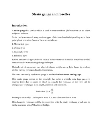
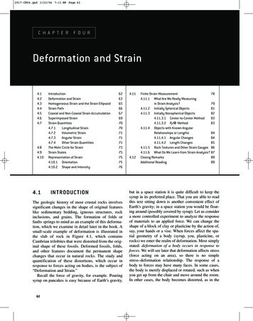
2917-CH04.qxd 1/23/04 7:11 AM Page 62CHAPTER FOURDeformation and onDeformation and StrainHomogeneous Strain and the Strain EllipsoidStrain PathCoaxial and Non-Coaxial Strain AccumulationSuperimposed StrainStrain Quantities4.7.1Longitudinal Strain4.7.2Volumetric Strain4.7.3Angular Strain4.7.4Other Strain QuantitiesThe Mohr Circle for StrainStrain StatesRepresentation of Strain4.10.1 Orientation4.10.2 Shape and IONThe geologic history of most crustal rocks involvessignificant changes in the shape of original featureslike sedimentary bedding, igneous structures, rockinclusions, and grains. The formation of folds orfaults springs to mind as an example of this deformation, which we examine in detail later in the book. Asmall-scale example of deformation is illustrated inthe slab of rock in Figure 4.1, which containsCambrian trilobites that were distorted from the original shape of these fossils. Deformed fossils, folds,and other features document the permanent shapechanges that occur in natural rocks. The study andquantification of these distortions, which occur inresponse to forces acting on bodies, is the subject of“Deformation and Strain.”Recall the force of gravity, for example. Pouringsyrup on pancakes is easy because of Earth’s gravity,624.114.12Finite Strain Measurement784.11.1 What Are We Really Measuringin Strain Analysis?794.11.2 Initially Spherical Objects814.11.3 Initially Nonspherical Objects824.11.3.1 Center-to-Center Method834.11.3.2 Rf/Φ Method834.11.4 Objects with Known AngularRelationships or Lengths844.11.4.1 Angular Changes844.11.4.2 Length Changes854.11.5 Rock Textures and Other Strain Gauges 864.11.6 What Do We Learn from Strain Analysis? 87Closing Remarks89Additional Reading89but in a space station it is quite difficult to keep thesyrup in its preferred place. That you are able to readthis text sitting down is another convenient effect ofEarth’s gravity; in a space station you would be floating around (possibly covered by syrup). Let us considera more controlled experiment to analyze the responseof materials to an applied force. We can change theshape of a block of clay or plasticine by the action of,say, your hands or a vise. When forces affect the spatial geometry of a body (syrup, you, plasticine, orrocks) we enter the realm of deformation. Most simplystated: deformation of a body occurs in response toforces. We will see later that deformation affects stress(force acting on an area), so there is no simplestress–deformation relationship. The response of abody to forces may have many faces. In some cases,the body is merely displaced or rotated, such as whenyou get up from the chair and move around the room.In other cases, the body becomes distorted, as in the
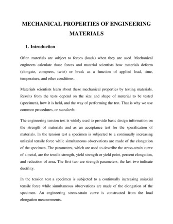
2917-CH04.qxd 1/23/04 7:11 AM Page 63F I G U R E 4 . 1 Deformed trilobites (Angelina sedgwicki) in a Cambrian slate from Wales.Knowledge about their original symmetry enables us to quantify the strain.clay block experiment or with the flow of syrup. In thischapter we will examine these responses both qualitatively and quantitatively.tial to the final shape. The displacement field can besubdivided into three components:1. A distortion (Figure 4.2b)2. A rotation (Figure 4.2c)3. A translation (Figure 4.2d)4.2DEFORMATION AND STRAINDeformation and strain are closely related terms that aresometimes used as synonyms, but they are not the same.Deformation describes the collective displacements ofpoints in a body; in other words, it describes the complete transformation from the initial to the final geometry of a body. This change can include a translation(movement from one place to the other), a rotation(spin around an axis), and a distortion (change inshape). Strain describes the changes of points in a bodyrelative to each other; so, it describes the distortion of abody. This distinction between deformation and strainmay not be immediately obvious from these abstractdescriptions, so we use an example. In Figure 4.2 wechange the shape and position of a square, say, a slice ofthe clay cube we used in Chapter 3. We arbitrarilychoose a reference frame with axes that parallel the margins of the printed page. The displacement of pointswithin the body, represented by the four corner points ofthe square, are indicated by vectors. These vectorsdescribe the displacement field of the body from the ini-Each component in turn can be described by a vectorfield (shown for point A only) and their sum gives thetotal displacement field. Importantly, a change in theorder of addition of these vector components affectsthe final result. Deformation, therefore, is not a vectorentity, but a second-order tensor (similar to stress). Wewill return to this later.When the rotation and distortion components arezero, we only have a translation. This translation is formally called rigid-body translation (RBT), becausethe body undergoes no shape change while it moves. Forconvenience, we will simply refer to this component astranslation, and the deformation is called translational.When the translation and distortion components arezero, we have only rotation of the body. By analogy totranslation, we call this component rigid-body rotation(RBR), or simply spin, and the corresponding deformation is called rotational. Recalling the pool table example of the previous chapter (Figure 3.2), the deformationof a pool ball that is hit is fully described by a translational and a spin component. When translation and spin4.2 DEFORMATION AND STRAIN63
2917-CH04.qxd 1/23/04 7:11 AM Page 64the window, however,makes you aware of thedisplacement by offeringB'an external referenceframe.BOne final element isAD'missing in our descriptionof deformation. In FigC'ure 4.2 we have constrained the shape changeof the square by maintainDCDeformationing a constant area. You(a)recall that shape changeresults from the deviatoric component of thestress, meaning where theprincipal stresses areunequal in magnitude(see Figure 3.12). Thehydrostatic component ofthe total stress, however,Xcontributes to deformaYtion by changing the area(or volume, in threedimensions) of an object.Area or volume change iscalled dilation2 and ispositive or negative, asTranslationDistortionRotation(d)(b)(c)the volume increases ordecreases, respectively.F I G U R E 4 . 2 The components of deformation. The deformation of a square (a) is subdividedBecause dilation resultsinto three independent components: (b) a distortion; (c) a rotation; and (d) a translation. Thein changes of line lengths itdisplacement of each material point in the square, represented by the four corners of the initialsquare, describes the displacement field. The corresponding strain ellipse is also shown. Theis similar to strain, exceptdistortion occurs along the axes X and Y, which are the principal strain axes.that the relative lengths ofthe lines remain the same.Thus, it is useful to distinguish strain from volumeare both zero, the body undergoes distortion; this comchange. In summary, deformation is described by:ponent is described by strain. So, strain is a componentof deformation and therefore not a synonym. In essence,1. Rigid-body translation (or translation)we have defined deformation and strain relative to a2. Rigid-body rotation (or spin)frame of reference. Deformation describes the com3. Strainplete displacement field of points in a body relative to an4. Volume change (or dilation)external reference frame, such as the edges of the paperon which Figure 4.2 is drawn. Strain, on the other hand,It is relatively difficult in practice to determine thedescribes the displacement field of points relative totranslational, spin, and dilational components of deforeach other. This requires a reference frame within themation. Only in cases where we are certain about thebody, an internal reference frame, like the edges of theoriginal position of a body can translation and spin besquare. Place yourself in the square and you woulddetermined, and only when we know the originalbe unaware of any translation, just as when you arevolume of a body can dilation be quantified. On theflying in an airplane or riding a train.1 Looking out ofA'1Weassume constant velocity; your stomach would notice acceleration.64DEFORMATION AND STRAIN2Ordilatation in the United Kingdom.
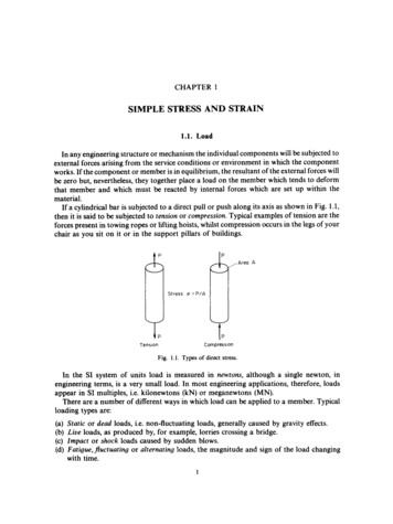
2917-CH04.qxd 1/23/04 7:11 AM Page 65other hand, we often do know the original shape of abody, so the quantification of strain is a common activity in structural geology.4.3(a)HOMOGENEOUS STRAINAND THE STRAINELLIP SOIDStrain describes the distortion of a body in response toan applied force. Strain is homogeneous when any twoportions of the body that were similar in form and orientation before are similar in form and orientation afterstrain. This can be illustrated by drawing a square anda circle on the edge of a deck of cards; homogeneousstrain changes a square into a parallelogram and a circle into an ellipse (Figure 4.3b). We define homogeneous strain by its geometric consequences:(b)(c)1. Originally straight lines remain straight.2. Originally parallel lines remain parallel.3. Circles become ellipses; in three dimensions,spheres become ellipsoids.When one or more of these three restrictions does notapply, we call the strain heterogeneous (Figure 4.3c).Because conditions (1) and (2) are maintained duringthe deformation components of translation and rotation,deformation is homogeneous by definition if the strainis homogeneous. Conversely, heterogeneous strainimplies heterogeneous deformation. Homogeneous andheterogeneous deformation should not be confusedwith rotational and nonrotational deformation; the latter reflect the presence of a spin component.Because heterogeneous strain is more complex todescribe than homogeneous strain, we try to analyzeheterogeneously strained bodies or regions by separating them into homogeneous portions. In otherwords, homogeneity of deformation is a matter ofscale. Consider a heterogeneous deformation feature like a fold, which can be approximated by threeessentially homogeneous sections: the two limbs andthe hinge (see Chapter 10 for fold terminology). Theheterogeneously deformed large square of Figure 4.3c consists of nine smaller squares for whichthe strain conditions are approximately homogeneous. Given the scale dependence of homogeneityand not to complicate our explanations unnecessarily,we will limit our discussion in this chapter to homogeneous strain.F I G U R E 4 . 3 Homogeneous and heterogeneous strain.A square and a circle drawn on a stack of cards (a) transforminto a parallelogram and an ellipse when each card slides thesame amount, which represents homogeneous strain (b).Heterogeneous strain (c) is produced by variable slip on thecards, for example by increasing the slip on individual cardsfrom bottom to top.In a homogeneously strained, two-dimensional bodythere will be at least two material lines that do notrotate relative to each other, meaning that their angleremains the same before and after strain. What is amaterial line? A material line connects features, such asan array of grains, that are recognizable throughout abody’s strain history. The behavior of four material linesis illustrated in Figure 4.4 for the two-dimensional case,yxF I G U R E 4 . 4 Homogeneous strain describes thetransformation of a square to a rectangle or a circle to anellipse. Two material lines that remain perpendicular beforeand after strain are the principal axes of the strain ellipse (solidlines). The dashed lines are material lines that do not remainperpendicular after strain; they rotate toward the long axis ofthe strain ellipse.4.3 HOMOGENEOUS STRAIN AND THE STRAIN ELLIPSOID65
2917-CH04.qxd 1/23/04 7:11 AM Page 66ellipsoids are not the same. We dedicate an entirechapter to the relationship between the stress and strainellipsoids (Chapter 5, “Rheology”), where you willexplore its complexity.in which a circle changes into an ellipse. In homogeneous strain, two orientations of material lines remainperpendicular before and after strain. These two material lines form the axes of an ellipse that is called thestrain ellipse. Note that the lengths of these two material lines change from the initial to the final stage; otherwise we would not strain our initial circle.Analogously, in three dimensions we have three material lines that remain perpendicular after strain andthey define the axes of an ellipsoid, the strain ellipsoid. The lines that are perpendicular before and afterstrain are called the principal strain axes. Theirlengths define the strain magnitude and we will use thesymbols X, Y, and Z to specify them, with the convention that X Y Z. In a more intuitive explanation, youmay consider the strain ellipsoid as the modified shapeof an initial sphere embedded in a body after the application of a homogeneous strain. We describe strain intwo-dimensional space by the two axes of the strainellipse and an angle describing the rotation of thisellipse. In three-dimensional space, therefore, we usethe three axes of the strain ellipsoid and three rotationangles. This means that the strain ellipsoid is definedby six independent components, which is reminiscentof the stress ellipsoid (see Section 3.6.2). Indeed, thestrain ellipsoid is a visual representation of a secondrank tensor, but keep in mind that the stress and strain4.4STRAIN PATHThe measure of strain that compares the initial andfinal configuration is called the finite strain, identifiedby subscript f, which is independent of the details ofthe steps toward the final configuration. When theseintermediate strain steps are determined they are calledincremental strains, identified by subscript i. Thesummation of all incremental strains (that is, theirproduct), therefore, is the finite strain. We will see thatthere are many ways to measure finite strain in a rock,but measurement of strain increments is more difficult.Yet, incremental strain may be more crucial for unraveling the deformation history of a rock or region thanfinite strain. Let us explore this with a simple example(Figure 4.5).Finite strains for the distortion of a square inFigures 4.5a and 4.5b are the same, because the initialand final configurations are identical. The steps orstrain increments by which these final shapes (1)(2)(3)(b)F I G U R E 4 . 5 The finite strains, Xf and Yf, in (a) and (b) are the same, but the strain path bywhich each was reached is different. This illustrates the importance of understanding theincremental strain history (here, Xi and Yi) of rocks and regions and inherent limitation of finitestrain analysis.66DEFORMATION AND STRAIN(4)
2917-CH04.qxd 1/23/04 7:11 AM Page 67reached, however, are very different. We say that thestrain path of the two examples is different, but thefinite strains are the same. The path presented inFigure 4.5a has incremental strains that reflect a strainellipse that becomes increasingly elliptical; in otherwords, the ratio of the long over the short axis (X/Y)becomes greater. The path in Figure 4.5b, on the otherhand, shows that the orientation of the Xi and Yi axeswas perpendicular to those of the finite strain ellipseduring part of the history. Consider this in a geologiccontext: the two paths would represent very differentstrain histories of a region, yet their finite strainswould be identical. Obviously, an important piece ofinformation is lost without knowledge of the strainpath. It is therefore critical for structural analysis todistinguish finite strain from incremental strain. Butbecause incremental strains are harder to determine,structural geologists imply finite strain when theyloosely discuss the “strain” of a rock or a region.4.5COAXIAL AND NON-COAXIALSTRAIN ACCUMUL ATIONEarlier (Figure 4.4) we saw that strain involves therotation of material lines. Recall that a material line ismade up of a series of points in a body; for example, arow of calcium atoms in a calcite crystal or an array s in a quartzite. There is no mechanical contrastbetween the material line and the body as a whole, sothat material lines behave as passive markers. Allmaterial lines in the body, except those that remainperpendicular before and after a strain increment (thatis, the principal strain axes), rotate relative to eachother. In the general case for strain, the principal incremental strain axes are not necessarily the samethroughout the strain history. In other words, the principal incremental strain axes rotate relative to the finitestrain axes, a scenario that is called non-coaxial strainaccumulation. The case in which the same materiallines remain the principal strain axes at each incrementis called coaxial strain accumulation. These important concepts are not obvious, so we turn to a classroom experiment for further exploration.First we examine non-coaxial strain accumulation.Take a deck of playing cards (or a thick phone book)and draw a circle on the face perpendicular to thecards. By sliding the cards past one another by roughlyequal amounts, the initial circle changes into an ellipse(Figure 4.6a). Draw the ellipse axes (i.e., incrementalstrain axes) X1 and Y1 on the face. Continuing to slidethe cards produces a more elliptical shape. Again markthe ellipse axes X2 and Y2 of this second step on thecards, but use another color. Continue this action athird time so that in the end you have three steps(increments) and three X-Y pairs. Note that the lastellipse represents the finite strain. Now, as you )(b)F I G U R E 4 . 6 Non-coaxial (a) and coaxial (b) strain. The incremental strain axes are differentmaterial lines during non-coaxial strain. In coaxial strain the incremental strain axes are parallel tothe same material lines. Note that the magnitude of the strain axes changes with each step.4.5 COAXIAL AND NON-COAXIAL STRAIN ACCUMULATION67
2917-CH04.qxd 1/23/04 7:11 AM Page 68(a)F I G U R E 4 . 7 A combination of simple shear (a special case of noncoaxial strain) and pure shear (coaxial strain) is called general shear orgeneral non-coaxial strain. Two types of general shear are transtension(a) and transpression (b), reflecting extension and shorteningcomponents.(b)α(a)(b)(c)(d)F I G U R E 4 . 8 Particle paths or flow lines during progressive strain accumulation. These flowlines represent pure shear (a), general shear (b), simple shear (c), and rigid-body rotation (d). Thecosine of the angle α is the kinematic vorticity number, Wk, for these strain histories; Wk 0, 0 Wk 1,Wk 1, and Wk , respectively.the cards to their starting configuration, by restoringthe original circle, you will notice that the pairs ofstrain axes of the three increments do not coincide. Foreach step a different set of material lines maintainedperpendicularity, and thus the incremental strain axesdo not coincide with the finite strain axes. You also seethat with each step the long axis of the finite strainellipse rotated more toward the shear plane over whichthe cards slide. You can imagine that a very largeamount of sliding will orient the long axis of the finitestrain ellipse nearly parallel to (meaning a few degreesoff) the shear plane.In the case of coaxial strain accumulation we returnto our earlier experiment with clay (Figure 4.6b). Takea slice of clay with a circle drawn on its front surfaceand press down on the top and bottom. When you drawthe incremental strain axes at various steps, you willnotice that they coincide with one another, while theellipticity (the X/Y ratio) increases. So, with coaxialstrain accumulation there is no rotation of the incremental strain axes with respect to the finite strain axes.3The component describing the rotation of materiallines with respect to the principal strain axes is calledthe internal vorticity, which is a measure of the degreeof non-coaxiality. If there is zero internal vorticity, thestrain history is coaxial (as in Figure 4.6b), which issometimes called pure shear. The non-coaxial strain3Inkinematic theory we use the infinitesimally small incremental strainaxes or the instantaneous strain axes.68DEFORMATION AND STRAINhistory in Figure 4.6a describes the case in which thedistance perpendicular to the shear plane (or the thickness of our stack of cards) remains constant; this isalso known as simple shear. In reality, a combinationof simple shear and pure shear occurs, which we callgeneral shear (or general non-coaxial strain accumulation; Figure 4.7). Internal vorticity is quantifiedby the kinematic vorticity number, Wk, which relatesthe angular velocity and the stretching rate of materiallines. Avoiding the math, a convenient graphical wayto understand this parameter is shown in Figure 4.8.When tracking the movement of individual pointswithin a deforming body relative to a reference line,we obtain a displacement field (or flow lines) thatenables us to quantify the internal vorticity. The angular relationship between the asymptote and the reference line defines Wk:Wk cos αEq. 4.1For pure shear Wk 0 (Figure 4.8a), for general shear0 Wk 1 (Figure 4.8b), and for simple shear Wk 1(Figure 4.8c). Rigid-body rotation or spin can also bedescribed by the kinematic vorticity number (in thiscase, Wk ; Figure 4.8d), but remember that thisrotational component of deformation is distinct fromthe internal vorticity of strain. Using Figure 4.6 as anexample, the deformation history shown in Figure 4.6arepresents non-coaxial, nonrotational deformation.The orientation of the shear plane does not rotatebetween each step, but the incremental strain axes do
2917-CH04.qxd 1/23/04 7:11 AM Page 69TABLE 4.1TYPES OF STRAINCoaxial strainStrain in which the incremental strain axes remain parallel to the finite strain axes duringprogressive strainHeterogeneous strainStrain in which any two portions of a body similar in form and orientation before strain undergorelative change in form and orientation (also: inhomogeneous strain)Homogeneous strainStrain in which any two portions of a body similar in form and orientation before strain remain similarin form and orientation after strainIncremental strainStrain state of one step in a progressive strain historyInstantaneous strainIncremental strain of vanishingly small magnitude (a mathematical descriptor); also calledinfinitesimal incremental strainFinite strainStrain that compares the initial and final strain configurations; sometimes called total strainNon-coaxial strainStrain in which the incremental strain axes rotate relative to the finite strain axes during progressivestrainExtensionEvent 1ShorteningFinite strainIEvent 2III(a) CoaxialsuperimpositionIIIIIIIIIIV(b) Non-coaxialsuperimpositionIIIIIIIIIIIVIrotate. The strain history in Figure 4.6b representscoaxial, nonrotational deformation, because the incremental axes remain parallel.Already, several types of strain have been introduced,so we summarize them in Table 4.1 before continuing.4.6SUPERIMPOSED STRAINThe strain path describes the superimposition of aseries of strain increments. For each of these incre-F I G U R E 4 . 9 Superimposed strain.The strain ellipse contains regions inwhich lines are extended and regionswhere lines are shortened, which areseparated by lines of zero finiteelongation. (a) Coaxial superimposition ofa strain event 2 produces regions inwhich lines continue to be extended (I),and regions where lines continue to beshortened (II), separated by regionswhere shortening during event 1 isfollowed by extension during event 2 (III).(b) Non-coaxial superimpositionadditionally produces a region whereextension is followed by shorteningduring event 2 (IV). Practically thismeans that structures reflecting differentstrain states may be formed, especiallyin non-coaxial strain regimes such asshear zones.ments the body is divided into regions containingmaterial lines that extend and shorten; these regionsare separated by planes containing lines with zerolength change. Considering only the two-dimensionalcase (Figure 4.9) we recognize regions of extensionand regions of shortening separated along two lines ofzero length change in the strain ellipse. When we coaxially superimpose a second strain increment on the firstellipse, we obtain three regions (Figure 4.9a): (I) aregion of continued extension, (II) a region of continued shortening, and (III) a region of initial shortening4.6 SUPERIMPOSED STRAIN69
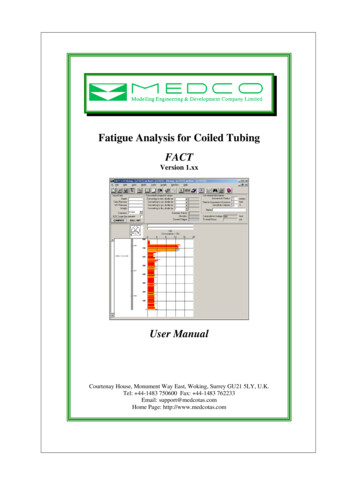
2917-CH04.qxd 1/23/04 7:11 AM Page 70F I G U R E 4 . 1 0 A small fold in turbidites from the Newfoundland Appalachians (Canada). Anaxial plane cleavage is visible in the mica-rich layer. Lens cover for scale.that is now in extension. The geometry is a little morecomplex when the incremental strain history is noncoaxial. Superimposing an increment non-coaxially onthe first strain state results in four regions (Figure 4.9b): (I) a region of continued extension, (II) aregion of continued shortening, (III) a region of initialshortening that is now in extension, and (IV) a regionof extension that is now in shortening. Clearly, superimposition of significant strain increments can producecomplex deformation patterns in rocks. For example,extensional structures formed during one part of thedeformation history may become shortened during alater part of the history, resulting in outcrop patternsthat, at first glance, may seem contradictory.4.7STRAIN QUANTITIESHaving examined the necessary fundamentals of strain,we can now turn our attention to practical applicationsin structural analysis using the quantification of strain.70DEFORMATION AND STRAINTake the small fold with axial plane clearage shown inFigure 4.10. How much strain does this deformation feature represent? How do we go about determining this? Inthe next sections we will examine strain quantificationusing three measures: length change or longitudinalstrain, volume change or volumetric strain, and angular change or angular strain. You’ll find that all of theseapproaches are pertinent to the analysis of our little fold.4.7.1Longitudinal StrainLongitudinal strain is defined as a change in lengthdivided by the original length. Longitudinal strain isexpressed by the elongation, e, which is defined ase (l - lo)/loore δl/loEq. 4.2where l is the final length, lo is the original length, andδl is the length change (Figure 4.11a). Because wedivide values with the same units, longitudinal strain isa dimensionless quantity. A longitudinal strain of
2917-CH04.qxd 1/23/04 7:11 AM Page 710.3 for a stretched rod or acontinental region is independent of the originaldimensions of the object.This definition of elongation implies that negativevalues of e reflect shortening whereas positive valuesof e represent extension.We label the maximum,intermediate, and minimum elongations, e1, e2,and e3, respectively, withe1 e2 e3. Remember thesign convention we justdescribed! In practice,geologists commonly givethe elongation in percent,using the absolute value, e 100%, and the termsshortening and extensioninstead of a negative orpositive sign; for example, 30% extension or40% shortening.4.7.2 ᐉoᐉ ᐉe ᐉ – ᐉo ᐉ ;ᐉoᐉos ᐉᐉo tan (a)Y/ 2 P δV/VoEq. 4.3Angular StrainLongitudinal and volumetric strain are relativelystraightforward and easily defined strain parameters.Angular strains are slightly more difficult to handle asthey measure the change in angle between two linesthat were initially perpendicular. The change in angleis called the angular shear, ψ, but more commonly weuse the tangent of this angle, called the shear strain, γ(Figure 4.11b):γ tan ψP' X/ 1XX/ 1(d)F I G U R E 4 . 1 1 Strain quantities. The elongation, e, and stretch, s, in (a); the angular shear, ψ,and the shear strain, γ, in (b). In (c) the relationships between quadratic elongation (λ), stretch(s), and angular shear (ψ) are shown for line OP that transforms into OP' (d).where V is the final volume, Vo is the original volume,and δV is the volume change. Like longitudinal strain,volumetric strain is a ratio of values with the sameunits, so it also is a dimensionless quantity. Positivevalues for represent volume gain, whereas negativevalues represent volume loss.4.7.3Y(c)A relationship similar to that for length changes holdsfor three-dimensional (volume) change. For volumetric strain, , the relationship isor(b)Y/ 2Volumetric Strain (V – Vo)/Vo Eq. 4.4Like the longitudinal and volumetric strains, the shearstrain is a dimensionless parameter.4.7.4Other Strain QuantitiesIn calculations such as those associated with the Mohrcircle for strain (see Section 4.8), we make use of aquantity called the quadratic elongation, λ, which isdefined asλ (l/lo)2 (1 e)2Eq. 4.5where l is the final length, lo is the original length, ande is the elongation.The root of the quadratic elongation is called thestretch, s, which is a convenient strain parameter thatdirectly relates to the dimensions of the strain ellipsoid:s λ1/2 l/lo 1 eEq. 4.6The quadratic elongation, λ, and especially the stretch,s, are convenient measures because they describe thelengths of the principal axes (X, Y, and Z) of the strainellipsoid:X s1, Y s2, Z s34.7 STRAIN QUANTITIESEq. 4.771
2917-CH04.qxd 1/23/04 7:11 AM Page 72with X Y Z, andX 2 λ1, Y 2 λ2, Z 2 λ3Eq. 4.8This relationship between the quadratic elongation,stretches, and the strain ellipse is illustrated in twodimensions in Figure 4.11c. A circle with unit radius(r 1) becomes distorted into an ellipse that is definedby the length of axes λ 1 (i.e., X) and λ 2 (i.e., Y).As a consequence of this distortion, a line OP at an initial angle of ϕ with the X-axis becomes elongated(OP') with an angle ϕ' to the λ1/X-axis.4 FromFigure 4.11c you can determine that the relationshipbetween ϕ and ϕ' is described bytan ϕ' Y/X tan ϕ (λ2/λ1)1/2 tan ϕEq. 4.9or, rearranging this equationtan ϕ
4.3 Homogeneous Strain and the Strain Ellipsoid 65 4.4 Strain Path 66 4.5 Coaxial and Non-Coaxial Strain Accumulation 67 4.6 Superimposed Strain 69 4.7 Strain Quantities 70 4.7.1 Longitudinal Strain 70 4.7.2 Volumetric Strain 71 4.7.3 Angular Strain 71 4.7.4 Other Strain Quantities 71 4.8 The Mohr Circle for