Transcription
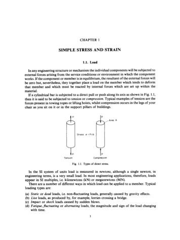
CHAPTER 1SIMPLE STRESS AND STRAIN1.1. LoadIn any engineering structure or mechanism the individual components will be subjected toexternal forces arising from the service conditions or environment in which the componentworks. If the component or member is in equilibrium, the resultant of the external forces willbe zero but, nevertheless, they together place a load on the member which tends to deformthat member and which must be reacted by internal forces which are set up within thematerial.If a cylindrical bar is subjected to a direct pull or push along its axis as shown in Fig. 1.1,then it is said to be subjected to tension or compression. Typical examples of tension are theforces present in towing ropes or lifting hoists, whilst compression occurs in the legs of yourchair as you sit on it or in the support pillars of buildings.,Are0TensionACompressionFig. 1.1. Types of direct stress.In the SI system of units load is measured in newtons, although a single newton, inengineering terms, is a very small load. In most engineering applications, therefore, loadsappear in SI multiples, i.e. kilonewtons (kN) or meganewtons (MN).There are a number of different ways in which load can be applied to a member. Typicalloading types are:(a) Static or dead loads, i.e. non-fluctuating loads, generally caused by gravity effects.(b) Liue loads, as produced by, for example, lorries crossing a bridge.(c) Impact or shock loads caused by sudden blows.(d) Fatigue,fluctuating or alternating loads, the magnitude and sign of the load changingwith time.1
2Mechanics of Materials 1.21.2. Direct or normal stress (a)It has been noted above that external force applied to a body in equilibrium is reacted byinternal forces set up within the material. If, therefore, a bar is subjected to a uniform tensionor compression, i.e. a direct force, which is uniformly or equally applied across the crosssection, then the internal forces set up are also distributed uniformly and the bar is said to besubjected to a uniform direct or normal stress, the stress being defined asload Pstress (a) - area AStress CT may thus be compressive or tensile depending on the nature of the load and will bemeasured in units of newtons per square metre (N/mZ)or multiples of this.In some cases the loading situation is such that the stress will vary across any given section,and in such cases the stress at any point is given by the limiting value of 6 P / 6 A as 6 A tends tozero.1.3. Direct strain ( E )If a bar is subjected to a direct load, and hence a stress, the bar will change in length. If thebar has an original length L and changes in length by an amount 6L, the strain produced isdefined as follows:strain ( E ) change in length -6 Loriginal lengthLStrain is thus a measure of the deformation of the material and is non-dimensional,Le. it hasno units; it is simply a ratio of two quantities with the same unit (Fig. 1.2).Strain C G L / LFig. 1.2.Since, in practice, the extensions of materials under load are very small, it is ofteni.e. microstrain, when theconvenient to measure the strains in the form of strain xsymbol used becomes /ALE.Alternatively, strain can be expressed as a percentage straini.e.6Lstrain ( E ) - x 100%L1.4. Sign convention for direct stress and strainTensile stresses and strains are considered POSITIVE in sense producing an increase inlength. Compressive stresses and strains are considered NEGATIVE in sense producing adecrease in length.
1.5Simple Stress and Strain31.5. Elastic materials - Hooke’s lawA material is said to be elastic if it returns to its original, unloaded dimensions when load isremoved. A particular form of elasticity which applies to a large range of engineeringmaterials, at least over part of their load range, produces deformations which areproportional to the loads producing them. Since loads are proportional to the stresses theyproduce and deformations are proportional to the strains, this also implies that, whilstmaterials are elastic, stress is proportional to strain. Hooke’s law, in its simplest form*,therefore states thatstress (a) a strain ( E )i.e.stress-- constant*strainIt will be seen in later sections that this law is obeyed within certain limits by most ferrousalloys and it can even be assumed to apply to other engineering materials such as concrete,timber and non-ferrous alloys with reasonable accuracy. Whilst a material is elastic thedeformation produced by any load will be completely recovered when the load is removed;there is no permanent deformation.Other classifications of materials with which the reader should be acquainted are asfollows:A material which has a uniform structure throughout without any flaws or discontinuitiesis termed a homogeneous material. Non-homogeneous or inhomogeneous materials such asconcrete and poor-quality cast iron will thus have a structure which varies from point to pointdepending on its constituents and the presence of casting flaws or impurities.If a material exhibits uniform properties throughout in all directions it is said to beisotropic; conversely one which does not exhibit this uniform behaviour is said to be nonisotropic or anisotropic.An orthotropic material is one which has different properties in different planes. A typicalexample of such a material is wood, although some composites which contain systematicallyorientated “inhomogeneities” may also be considered to fall into this category.1.6. Modulus of elasticity - Young’s modulusWithin the elastic limits of materials, i.e. within the limits in which Hooke’s law applies, ithas been shown thatstress-- constantstrainThis constant is given the symbol E and termed the modulus of elasticity or Young’s modulus.ThusE - stress-0strain EP 6 L --PLA ’ LASL --I--* Readers should be warned that in more complex stress cases this simple form of Hooke’s law will not apply andmisapplication could prove dangerous; see 814.1, page 361.
Mechanics of Materials4 1.7Young’s modulus E is generally assumed to be the same in tension or compression and formost engineering materials has a high numerical value. Typically, E 200 x lo9 N/m2 forsteel, so that it will be observed from (1.1) that strains are normally very small sinceE -0EIn most common engineering applications strains do not often exceed 0.003 or 0.3 % sothat the assumption used later in the text that deformations are small in relation to originaldimensions is generally well founded.The actual value of Young’s modulus for any material is normally determined by carryingout a standard tensile test on a specimen of the material as described below.1.7. Tensile testIn order to compare the strengths of various materials it is necessary to carry out somestandard form of test to establish their relative properties. One such test is the standard tensiletest in which a circular bar of uniform cross-section is subjected to a gradually increasingtensile load until failure occurs. Measurements of the change in length of a selected gaugelength of the bar are recorded throughout the loading operation by means of extensometersand a graph of load against extension or stress against strain is produced as shown in Fig. 1.3;this shows a typical result for a test on a mild (low carbon) steel bar; other materials willexhibit differentgraphs but of a similar general form see Figs 1.5 to 1.7.ElasticP a r t i a l l y plastictPExtension or strainFig. 1.3. Typical tensile test curve for mild steel.For the first part of the test it will be observed that Hooke’s law is obeyed, Le. the materialbehaves elastically and stress is proportional to strain, giving the straight-line graphindicated. Some point A is eventually reached, however, when the linear nature of the graphceases and this point is termed the limit of proportionality.For a short period beyond this point the material may still be elastic in the sense thatdeformations are completely recovered when load is removed (i.e. strain returns to zero) but
51.75Simple Stress and StrainHooke’s law does not apply. The limiting point B for this condition is termed the elastic limit.For most practical purposes it can often be assumed that points A and B are coincident.Beyond the elastic limit plastic deformation occurs and strains are not totally recoverable.There will thus be some permanent deformation or permanent set when load is removed.After the points C, termed the upper yield point, and D, the lower yield point, relatively rapidincreases in strain occur without correspondinglyhigh increases in load or stress. The graphthus becomes much more shallow and covers a much greater portion of the strain axis thandoes the elastic range of the material. The capacity of a material to allow these large plasticdeformations is a measure of the so-called ductility of the material, and this will be discussedin greater detail below.For certain materials, for example, high carbon steels and non-ferrous metals, it is notpossible to detect any difference between the upper and lower yield points and in some casesno yield point exists at all. In such cases a proof stress is used to indicate the onset of plasticstrain or as a comparison of the relative properties with another similar material. Thisinvolves a measure of the permanent deformation produced by a loading cycle; the 0.1 %proof stress, for example, is that stress which, when removed, produces a permanent strain or“set” of 0.1 % of the original gauge length-see Fig. 1.4(a).b”7rE- Fi5I’cI0 I % 1Fig. 1.4. (a) Determination of 0.1 % proof stress.\Permanent ‘ s e t ’Fig. 1.4. (b) Permanent deformation or “set” afterstraining beyond the yield point.The 0.1 % proof stress value may be determined from the tensile test curve for the materialin question as follows:Mark the point P on the strain axis which is equivalent to 0.1 % strain. From P draw a lineparallel with the initial straight line portion of the tensile test curve to cut the curve in N. Thestress corresponding to Nis then the 0.1 %proof stress. A material is considered to satisfy itsspecificationif the permanent set is no more than 0.1 %after the proof stress has been appliedfor 15 seconds and removed.Beyond the yield point some increase in load is required to take the strain to point E on thegraph. Between D and E the material is said to be in the elastic-plastic state, some of thesection remaining elastic and hence contributing to recovery of the original dimensions ifload is removed, the remainder being plastic. Beyond E the cross-sectional area of the bar
601.7Mechanics of Materialsbegins to reduce rapidly over a relatively small length of the bar and the bar is said to neck.This necking takes place whilst the load reduces, and fracture of the bar finally occurs atpoint F.The nominal stress at failure, termed the maximum or ultimate tensile stress, is given by theload at E divided by the original cross-sectional area of the bar. (This is also known as thetensile strength of the material of the bar.) Owing to the large reduction in area produced bythe necking process the actual stress at fracture is often greater than the above value. Since,however, designers are interested in maximum loads which can be carried by the completecross-section, the stress at fracture is seldom of any practical value.If load is removed from the test specimen after the yield point C has been passed, e.g. tosome position S, Fig. 1.4(b), the unloading line STcan, for most practical purposes, be taken tobe linear. Thus, despite the fact that loading to S comprises both elastic (OC)and partiallyplastic (CS) portions, the unloading procedure is totally elastic. A second load cycle,commencing with the permanent elongation associated with the strain OT, would then followthe line TS and continue along the previous curve to failure at F. It will be observed, however,that the repeated load cycle has the effect of increasing the elastic range of the material, i.e.raising the effective yield point from C to S, while the tensile strength is unaltered. Theprocedure could be repeated along the line PQ, etc., and the material is said to have been workhardened.In fact, careful observation shows that the material will no longer exhibit true elasticitysince the unloading and reloading lines will form a small hysteresis loop, neither beingprecisely linear. Repeated loading and unloading will produce a yield point approaching theultimate stress value but the elongation or strain to failure will be much reduced.Typical stress-strain curves resulting from tensile tests on other engineering materials areshown in Figs 1.5 to 1.7.1500trchrome steel/NickelMedium carbon steel -u-?!&i6000YI0I20I40I30Strain.%Fig. 1.5. Tensile test curves for various metals.I50
7Simple Stress and Strain 1.7Strain,%Fig. 1.6. Typical stressstrain curves for hard drawn wire material-notelarge reduction in strain values from those of Fig. 1.5.Glass remforced polycarbonateeo’ II in,%Fig. 1.7. Typical tension test results for various types of nylon and polycarbonate.After completing the standard tensile test it is usually necessary to refer to some “BritishStandard Specification” or “Code of Practice” to ensure that the material tested satisfies therequirements, for example:BS 4360BS 970BS 153BS 449British Standard Specification for Weldable Structural Steels.British Standard Specification for Wrought Steels.British Standard Specification for Steel Girder Bridges.British Standard Specification for the use of Structural Steel in Building, etc.
8Mechanics of Materials51.81.8. Ductile materialsIt has been observed above that the partially plastic range of the graph of Fig. 1.3 covers amuch wider part of the strain axis than does the elastic range. Thus the extension of thematerial over this range is considerably in excess of that associated with elastic loading. Thecapacity of a material to allow these large extensions, i.e. the ability to be drawn outplastically, is termed its ductility. Materials with high ductility are termed ductile materials,members with low ductility are termed brittle materials. A quantitative value of the ductility isobtained by measurements of the percentage elongation or percentage reduction in area, bothbeing defined below.Percentage elongation Percentage reduction in area increase in gauge length to fracturex loooriginal gauge lengthreduction in cross-sectionalarea of necked portionx 100original areaThe latter value, being independent of any selected gauge length, is generally taken to be themore useful measure of ductility for reference purposes.A property closely related to ductility is malleability, which defines a material's ability to behammered out into thin sheets. A typical example of a malleable material is lead. This is usedextensively in the plumbing trade where it is hammered or beaten into corners or joints toprovide a weatherproof seal. Malleability thus represents the ability of a material to allowpermanent extensions in all lateral directions under compressive loadings.1.9. Brittle materialsA brittle material is one which exhibits relatively small extensions to fracture so that thepartially plastic region of the tensile test graph is much reduced (Fig. 1.8). Whilst Fig. 1.3referred to a low carbon steel, Fig. 1.8 could well refer to a much higher strength steel with ahigher carbon content. There is little or no necking at fracture for brittle materials.EFig. 1.8. Typical tensile test curve for a brittle material.Typical variations of mechanical properties of steel with carbon content are shown inFig. 1.9.
1.109Simple Stress and Straini90II0 204I0806Yo10cFig. 1.9. Variation of mechanical properties of steel with carbon content.1.10. Poisson’s ratioConsider the rectangular bar of Fig. 1.10 subjected to a tensile load. Under the action ofthis load the bar will increase in length by an amount 6 L giving a longitudinal strain in the barof6LEL LFig. 1.10.The bar will also exhibit, however, a reduction in dimensions laterally, i.e. its breadth anddepth will both reduce. The associated lateral strains will both be equal, will be of oppositesense to the longitudinal strain, and will be given by&l,t 6b6d-- - - bdProvided the load on the material is retained within the elastic range the ratio of the lateraland longitudinal strains will always be constant. This ratio is termed Poisson’s ratio.1.e.Poisson’s ratio ( v ) lateral strain - ( - 6 d / d )longitudinal strain6LIL(1.4)The negative sign of the lateral strain is normally ignored to leave Poisson’s ratio simply as
10Mechanics of Materials 1.11a ratio of strain magnitudes. It must be remembered, however, that the longitudinal straininduces a lateral strain of opposite sign, e.g. tensile longitudinal strain induces compressivelateral strain.For most engineering materials the value of v lies between 0.25 and 0.33.Sincelongitudinal stress - alongitudinal strain (1.4a)Young’s modulus EHencedlateral strain v E(1.4b)1.11. Application of Poisson’s ratio to a two-dimensional stress systemA two-dimensional stress system is one in which all the stresses lie within one plane such asthe X-Y plane. From the work of 1.10 it will be seen that if a material is subjected to a tensilestress a on one axis producing a strain u / E and hence an extension on that axis, it will besubjected simultaneously to a lateral strain of v times a/E on any axis at right angles. Thislateral strain will be compressive and will result in a compression or reduction of length onthis axis.Consider, therefore, an element of material subjected to two stresses at right angles to eachother and let both stresses, ux and c y ,be considered tensile, see Fig. 1.11.Fig. 1.11. Simple twodimensional system of direct stresses.The following strains will be produced(a)(b)(c)(d)ininininthe X direction resulting from ax a,/E,the Y direction resulting from cy a,/E.the X direction resulting from 0, - v(a,/E),the Y direction resulting from ax - v(a,/E).strains (c) and (d) being the so-called Poisson’s ratio strain, opposite in sign to the appliedstrains, i.e. compressive.The total strain in the X direction will therefore be given by:&“6”1E - - v o y -(axEE- va,)(1.5)
g1.1211Simple Stress and Strainand the total strain in the Y direction will be:If any stress is, in fact, compressive its value must be substituted in the above equationstogether with a negative sign following the normal sign convention.1.12. Shear stressConsider a block or portion of material as shown in Fig. 1.12a subjected to a set of equal andopposite forces Q.(Such a system could be realised in a bicycle brake block when contactedwith the wheel.) There is then a tendency for one layer of the material to slide over another toproduce the form of failure shown in Fig. 1.12b. If this failure is restricted, then a shear stress Tis set up, defined as follows:shear stress (z) shear loadQ-area resisting shear AThis shear stress will always be tangential to the area on which it acts; direct stresses, however,are always normal to the area on which they act.Q(a)(b)Fig. 1.12. Shear force and resulting shear stress system showing typical form of failure byrelative sliding of planes.1.13. Shear strainIf one again considers the block of Fig. 1.12a to be a bicycle brake block it is clear that therectangular shape of the block will not be retained as the brake is applied and the shear forcesintroduced. The block will in fact change shape or “strain” into the form shown in Fig. 1.13.The angle of deformation y is then termed the shear strain.Shear strain is measured in radians and hence is non-dimensional, i.e. it has no units.TFig. 1.13. Deformation (shear strain) produced by shear stresses.
12Mechanics of Materials01.141.14. Modulus of rigidityFor materials within the elastic range the shear strain is proportional to the shear stressproducing it,i.e.shear stress z - constant Gshear strain yThe constant G is termed the modulus of rigidity or shear modulus and is directlycomparable to the modulus of elasticity used in the direct stress application. The termmodulus thus implies a ratio of stress to strain in each case.1.15. Double shearConsider the simple riveted lap joint shown in Fig. 1.14a.When load is applied to the platesthe rivet is subjected to shear forces tending to shear it on one plane as indicated. In the buttjoint with two cover plates of Fig. 1.14b, however, each rivet is subjected to possible shearingon two faces, i.e. double shear. In such cases twice the area of metal is resisting the appliedforces so that the shear stress set up is given byshear stress r (in double shear)Simple riveted lop p m t --J&Failure ofrivet ,n singleP2A- e shearButt p m t wcrn t w o cover Platesla1lblFig. 1.14. (a) Single shear. (b) Double shear.1.16. Allowable working stress-factor of safetyThe most suitable strength or stiffness criterion for any structural element or component isnormally some maximum stress or deformation which must not be exceeded. In the case ofstresses the value is generally known as the maximum allowable working stress.Because of uncertainties of loading conditions, design procedures, production methods,etc., designers generally introduce a factor of safety into their designs, defined as follows:factor of safety maximum stressallowable working stress(1.9)However, in view of the fact that plastic deformations are seldom accepted this definition issometimes modified tofactor of safety yield stress (or proof stress)allowable working stress
51.1713Simple Stress and StrainIn the absence of any information as to which definition has been used for any quoted valueof safety factor the former definition must be assumed. In this case a factor of safety of 3implies that the design is capable of carrying three times the maximum stress to which it isexpected the structure will be subjected in any normal loading condition. There is seldom anyrealistic basis for the selection of a particular safety factor and values vary significantly fromone branch of engineering to another. Values are normally selected on the basis of aconsideration of the social, human safety and economic consequences of failure. Typicalvalues range from 2.5 (for relatively low consequence, static load cases) to 10 (for shock loadand high safety risk applications)-see 15.12.1.17. Load factorIn some loading cases, e.g. buckling of struts, neither the yield stress nor the ultimatestrength is a realistic criterion for failure of components. In such cases it is convenient toreplace the safety factor, based on stresses, with a different factor based on loads. The loadfactor is therefore defined as:load factor load at failureallowable working load(1.10)This is particularly useful in applications of the so-called plastic limit design procedures.1.18. Temperature stressesWhen the temperature of a component is increased or decreased the material respectivelyexpands or contracts. If this expansion or contraction is not resisted in any way then theprocesses take place free of stress. If, however, the changes in dimensions are restricted thenstresses termed temperature stresses will be set up within the material.Consider a bar of material with a linear coefficient of expansion a. Let the original length ofthe bar be L and let the temperature increase be t. If the bar is free to expand the change inlength would be given byb L Lat(1.11)and the new lengthL’ L Lat L ( l a t )If this extension were totally prevented, then a compressive stress would be set up equal tothat produced when a bar of length L ( 1 at) is compressed through a distance of Lat. In thiscase the bar experiences a compressive strainALLLatL(l at)E - In most cases at is very small compared with unity so thatLatLE --- at
14Mechanics of Materials81.19IS- EButE.stresst EE Eat(1.12)This is the stress set up owing to total restraint on expansions or contractions caused by atemperature rise, or fall, t. In the former case the stress is compressive, in the latter case thestress is tensile.If the expansion or contraction of the bar is partially prevented then the stress set up will beless than that given by eqn. (1.10).Its value will be found in a similar way to that describedabove except that instead of being compressed through the total free expansion distance ofLat it will be compressed through some proportion of this distance depending on the amountof restraint.Assuming some fraction n of Lat is allowed, then the extension which is prevented is( 1 - n)Lat. This will produce a compressive strain, as described previously, of magnitudeE (1-n)LatL(l at)or, approximately,E ( 1 - n ) L a t / L ( 1 -n)at.The stress set up will then be E times E .i.e.IS ( 1 -n)Eat(1.13)Thus, for example, if one-third of the free expansion is prevented the stress set up will be twothirds of that given by eqn. (1.12).1.19. Stress concentrations- stress concentration factorIf a bar of uniform cross-section is subjected to an axial tensile or compressive load thestress is assumed to be uniform across the section. However, in the presence of any suddenchange of section, hole, sharp corner, notch, keyway, material flaw, etc., the local stress willrise significantly. The ratio of this stress to the nominal stress at the section in the absence ofany of these so-called stress concentrations is termed the stress concentration factor.1.20. ToughnessToughness is defined as the ability of a material to withstand cracks, i.e. to prevent thetransfer or propagation of cracks across its section hence causing failure. Two distinct typesof toughness mechanism exist and in each case it is appropriate to consider the crack as a veryhigh local stress concentration.The first type of mechanism relates particularly to ductile materials which are generallyregarded as tough. This arises because the very high stresses at the end of the crack producelocal yielding of the material and local plastic flow at the crack tip. This has the action ofblunting the sharp tip of the crack and hence reduces its stressconcentration effectconsiderably (Fig. 1.15).
§1.21Simple Stress and Strain15Fig. 1.15. Toughness mechanism-typeThe second mechanism refers to fibrous, reinforced or resin-based materials which haveweak interfaces. Typical examples are glass-fibre reinforced materials and wood. It can beshown that a region of local tensile stress always exists at the front of a propagating crack andprovided that the adhesive strength of the fibre/resin interface is relatively low (one-fifth thecohesive strength of the complete material) this tensile stress opens up the interface andproduces a crack sink, i.e. it blunts the crack by effectively increasing the radius at the cracktip, thereby reducing the stress-concentration effect (Fig. 1.16).This principle is used on occasions to stop, or at least delay, crack propagation inengineering components when a temporary "repair" is carried out by drilling a hole at theend of a crack, again reducing its stress-concentration effect.Fig. 1.16. Toughness mechanism-type2.1.21. Creep and fatigueIn the preceding paragraphs it has been suggested that failure of materials occurs when theultimate strengths have been exceeded. Reference has also been made in §1.15 to caseswhereexcessive deformation, as caused by plastic deformation beyond the yield point, can beconsidered as a criterion for effective failure of components. This chapter would not becomplete, therefore, without reference to certain loading conditions under which materialscan fail at stresses much less than the yield stress, namely creep and fatigue.Creep is the gradual increase of plastic strain in a material with time at constant load.Particularly at elevated temperatures some materials are susceptible to this phenomenon andeven under the constant load mentioned strains can increase continually until fracture. Thisform of fracture is particularly relevant to turbine blades, nuclear reactors, furnaces, rocketmotors, etc.
16Mechanics of Materials51.21Fracture/High stress/7Fr oc t ureor temp//c?mcIt- tial ig. 1.17. Typical creep curve.The general form of the strain versus time graph or creep curve is shown in Fig. 1.17 for twotypical operating conditions. In each case the curve can be considered to exhibit fourprincipal features.(a) An initial strain, due to the initial application of load. In most cases this would be anelastic strain.(b) A primary creep region, during which the creep rate (slope of the graph) diminishes.(c) A secondary creep region, when the creep rate is sensibly constant.(d) A tertiary creep region, during which the creep rate accelerates to final fracture.It is clearly imperative that a material which is susceptible to creep effects should only besubjected to stresses which keep it in the secondary (straight line) region throughout itsservice life. This enables the amount of creep extension to be estimated and allowed for indesign.Fatigue is the failure of a material under fluctuating stresses each of which is believed toproduce minute amounts of plastic strain. Fatigue is particularly important in componentssubjected to repeated and often rapid load fluctuations, e.g. aircraft components, turbineblades, vehicle suspensions, etc. Fatigue behaviour of materials is usually described by afatigue life or S-N curve in which the number of stress cycles N to produce failure with astress peak of S is plotted against S. A typical S-N curve for mild steel is shown in Fig. 1.18.The particularly relevant feature of this curve is the limiting stress S, since it is assumed thatstresses below this value will not produce fatigue failure however many cycles areapplied, i.e. there is injinite life. In the simplest design cases, therefore, there is an aim to keepall stresses below this limiting level. However, this often implies an over-design in terms ofphysical size and material usage, particularly in ca
Strain C GL/L Fig. 1.2. Since, in practice, the extensions of materials under load are very small, it is often convenient to measure the strains in the form of strain x i.e. microstrain, when the symbol used becomes /ALE. Alternatively, strain can be expressed as a percentage strain