Transcription
PRACTICAL STRAIN GAGEMEASUREMENTSINTRODUCTIONWith today’s emphasis onproduct liability andenergy efficiency, designs must notonly be lighter and stronger, butalso more thoroughly tested thanever before. This places newimportance on the subject ofexperimental stress analysis andthe techniques for measuringstrain. The main theme of thisapplication note is aimed at strainmeasurements using bondedresistance strain gages. We willintroduce considerations that affectthe accuracy of this measurementand suggest procedures forimproving it.We will also emphasize thepractical considerations of straingage measurement, with anemphasis on computer controlledinstrumentation.Appendix B contains schematics ofmany of the ways strain gages areused in bridge circuits and theequations which apply to them.Readers wishing a more thoroughdiscussion of bridge circuittheory are invited to read Item7 referenced in the bibliography.STRAIN GAGESEE-94
PRACTICAL STRAIN GAGE MEASUREMENTSSYMBOLS normal stressRggage resistance in ohmsRllead wire resistanceshear stressKttransverse sensitivityratioTtemperature in ClengthVINVOUTbridge excitation voltageLstrain (normal) x 10 )micro-strain (6shear strainEmodulus of elasticityor Young’s modulusPoisson Ratio L change in length Rg change in gage resistancebridge output voltage(due to strain)% GF % change in gage factor(due to temperature)GF gage factorVr[(VOUT/VIN)[strained] — (VOUT/VIN)[unstrained]]STRESS & STRAINThe relationship betweenstress and strain is one of themost fundamental concepts fromthe study of the mechanics ofmaterials and is of paramountimportance to the stress analyst. Inexperimental stress analysis, weapply a given load and thenmeasure the strain on individualmembers of a structure or machine.Then we use the stress-strainrelationships to compute thestresses in those members to verifythat these stresses remain withinthe allowable limits for the particularmaterials used.Figure 1: Uniaxial Force Appliedcompressive (negative).See Figure 2. When this is written inequation form, L/L, we cansee that strain is a ratio and,therefore, dimensionless. STRAINWhen a force is applied to a body,the body deforms. In the generalcase, this deformation is calledstrain. In this application note, wewill be more specific and define theterm STRAIN to mean deformationper unit length or fractional changeFigure 2: Cantilever in Bending in length and give it the symbol, .See Figure 1. This is the strain thatwe typically measure with a bondedresistance strain gage. Strain maybe either tensile (positive) orE-95To maintain the physicalsignificance of strain, it is oftenwritten in units of inches/inch. Formost metals, the strains measuredin experimental work are typicallyless than 0.005000 inch/inch. Sincepractical strain values are so small.they are often expressed as microstrain, which is x 106 (note this isequivalent to parts per million orppm) with the symbol. Still
PRACTICAL STRAIN GAGE MEASUREMENTSanother way to express strain is aspercent strain, which is x 100. Forexample: 0.005 inch/inch 5000 0.5%. As described to this point, strain isfractional change in length and isdirectly measurable. Strain of thistype is also often referred to asnormal strain.Figure 4: Poisson StrainSHEARING STRAINAnother type of strain, calledSHEARING STRAIN, is a measureof angular distortion. Shearing strainis also directly measurable, but notas easily as normal strain. If we hada thick book sitting on a table topand we applied a force parallel tothe covers, we could see the shearstrain by observing the edges of thepages.pointing out another phenomenon,that of Poisson strain. The dashedlines indicate that the bar not onlyelongates but that its girth contracts.This contraction is a strain in thetransverse direction due to aproperty of the material known asPoisson’s Ratio. Poisson’s ratio, ,is defined as the negative ratio ofthe strain in the transverse directionto the strain in the longitudinaldirection. It is interesting to note thatno stress is associated with thePoisson strain. Referring to Figure4, the equation for Poisson’s ratio is – t / 1. Note that isdimensionless. Figure 3: Visualizing Shearing StrainSee Figure 3. Shearing strain, , isdefined as the angular change inradians between two line segmentsthat were orthogonal in theundeformed state. Since this angleis very small for most metals,shearing strain is approximated bythe tangent of the angle.While forces and strains aremeasurable quantities used by thedesigner and stress analyst, stressis the term used to compare theloading applied to a material with itsability to carry the load. Since it isThe bar in Figure 5 has a uniaxialtensile force, F, applied along thex-axis. If we assume the force to beuniformly distributed over the crosssectional area, A, the “average”stress on the plane of the section isF/A. This stress is perpendicular tothe plane and is called NORMALSTRESS, . Expressed in equationform, F/A, and is denoted inunits of force per unit area. Sincethe normal stress is in the xdirection and there is no componentof force in the y direction, there isno normal stress in that direction.The normal stress is in the positivex direction and is tensile.POISSON STRAINIn Figure 4 is a bar with a uniaxialtensile force applied, like the bar inFigure 1. The dashed lines show theshape of the bar after deformation,Figure 5: Normal StressE-96STRAIN GAGESNORMAL STRESSusually desirable to keep machinesand structures as small and light aspossible, component parts shouldbe stressed, in service, to thehighest permissible level. STRESSrefers to force per unit area on agiven plane within a body.E
PRACTICAL STRAIN GAGE MEASUREMENTSSHEAR STRESSJust as there are two types of strain,there is also a second type of stresscalled SHEAR STRESS. Wherenormal stress is normal to thedesignated plane, shear stress isparallel to the plane and has thesymbol . In the example shown inFigure 5, there is no y component offorce, therefore no force parallel tothe plane of the section, so there isno shear stress on that plane. Sincethe orientation of the plane isarbitrary, what happens if the planeis oriented other than normal to theline of action of the applied force?components, not the stresses, andthat the resulting stresses are afunction of the orientation of thesection. This means that stresses(and strains), while having bothmagnitude and direction, are notvectors and do not follow the laws ofvector addition, except in certainspecial cases, and they should notbe treated as such. We should alsonote that stresses are derivedquantities computed from othermeasurable quantities, and are notdirectly measurable. [3]Figure 6: Shear StressFigure 6 demonstrates this conceptwith a section taken on the n-tcoordinate system at some arbitraryangle, , to the direction of actionof the force.We see that the force vector, F, canbe broken into two components, Fnand Ft , that are normal and parallelto the plane of the section. Thisplane has a cross-sectional area ofA' and has both normal and shearstresses applied. The averagenormal stress, , is in the ndirection and the average shearstress, , is in the t direction. Theirequations are: Fn /A' and Ft /A'. Note that it was the forcevector that was broken intoPRINCIPAL AXESIn the preceding examples, the x-yaxes are also the PRINCIPAL AXESfor the uniaxially loaded bar. Bydefinition, the principal axes are theaxes of maximum and minimumnormal stress. They have theadditional characteristic of zeroshear stress on the planes that liealong these axes. In Figure 5, thestress in the x direction is themaximum normal stress, and wenoted that there was no forcecomponent in the y direction andtherefore zero shear stress on theplane. Since there is no force in they direction, there is zero normalE-97stress in the y direction and in thiscase zero is the minimum normalstress. So the requirements for theprincipal axes are met by the x-yaxes. In Figure 6, the x-y axes arethe principal axes, since that bar isalso loaded uniaxially. The n-t axesin Figure 6 do not meet the zeroshear stress requirement of theprincipal axes. The correspondingSTRAINS on the principal axes isalso maximum and minimum andthe shear strain is zero.The principal axes are veryimportant in stress analysis becausethe magnitudes of the maximumand minimum normal stresses areusually the quantities of interest.Once the principal stresses areknown, then the normal and shearstresses in any orientation can becomputed. If the orientation of theprincipal axes is known, throughknowledge of the loading conditionsor experimental techniques, the taskof measuring the strains andcomputing the stresses is greatlysimplified.In some cases, we are interested inthe average value of stress or loadon a member, but often we want todetermine the magnitude of thestresses at a specific point. Thematerial will fail at the point wherethe stress exceeds the load-carryingcapacity of the material. This failuremay occur because of excessivetensile or compressive normalstress or excessive shearing stress.In actual structures, the area of thisexcessive stress level may be quitesmall. The usual method ofdiagramming the stress at a point isto use an infinitesimal element thatsurrounds the point of interest. Thestresses are then a function of theorientation of this element, and, inone particular orientation, the
PRACTICAL STRAIN GAGE MEASUREMENTSelement will have its sides parallelto the principal axes. This is theorientation that gives the maximumand minimum normal stresses onthe point of interest.STRESS-STRAINRELATIONSHIPSNow that we have defined stressand strain, we need to explore thestress-strain relationship, for it isthis relationship that allows us tocalculate stresses from measuredstrains. If we have a bar made ofmild steel and incrementally load itin uniaxial tension and plot thestrain versus the normal stress inthe direction of the applied load, theplot will look like the stress-straindiagram in Figure 7.From Figure 7, we can see that, upto a point called the proportionallimit, there is a linear relationshipbetween stress and strain. Hooke’sLaw describes this relationship. Theslope of this straight-line portion ofthe stress-strain diagram is theMODULUS OF ELASTICITY orYOUNG’S MODULUS for thematerial. The modulus of elasticity,E, has the same units as stress(force per unit area) and isdetermined experimentally for The yield point is the stress level atwhich strain will begin to increaserapidly with little or no increase instress. If the material is stressedbeyond the yield point, and then thestress is removed, the material willnot return to its original dimensions,but will retain a residual offset orstrain. The ultimate strength is themaximum stress developed in thematerial before rupture.The examples we have examined tothis point have been examples ofuniaxial forces and stresses. Inexperimental stress analysis, theFigure 8: Shaft in Torsion and Tensionbiaxial stress state is the mostcommon. Figure 8 shows anexample of a shaft with both tensionand torsion applied. The point ofinterest is surrounded by aninfinitesimal element with its sidesoriented parallel to the x-y axes.The point has a biaxial stress stateand a triaxial strain state (rememberPoisson’s ratio). The element,rotated to be aligned with theprincipal (p-q) axes, is also shownin Figure 8. Figure 9 shows theelement removed with arrowsadded to depict the stresses at thepoint for both orientations of theelement.We see that the element orientedalong the x-y axes has a normalstress in the x direction, zero normalstress in the y direction and shearstresses on its surfaces. Theelement rotated to the p-q axesorientation has normal stress inFigure 9: Element on X-Y Axes and Principal AxesE-98STRAIN GAGESFigure 7: Stress-Strain Diagram forMild Steelmaterials. Written in equation form,this stress-strain relationship is E . Some materials do nothave a linear portion (for example,cast iron and concrete) to theirstress-strain diagrams. To doaccurate stress analysis studies forthese materials, it is necessary todetermine the stress-strainproperties, including Poisson’s ratio,for the particular material on atesting machine. Also, the modulusof elasticity may vary withtemperature. This variation mayneed to be experimentallydetermined and considered whenperforming stress analysis attemperature extremes. There aretwo other points of interest on thestress-strain diagram in Figure 7:the yield point and the ultimatestrength value of stress.E
PRACTICAL STRAIN GAGE MEASUREMENTSboth directions but zero shear stressas it should, by definition, if the p-qaxes are the principal axes. Thenormal stresses, p andq , arethe maximum and minimum normalstresses for the point. The strains inthe p-q direction are also themaximum and minimum, and thereis zero shear strain along theseaxes. Appendix C gives theequations relating stress to strain forthe biaxial stress state.If we know the orientation of theprincipal axes, we can then measurethe strain in those directions andcompute the maximum andminimum normal stresses and themaximum shear stress for a givenloading condition. We don’t alwaysknow the orientation of the principalaxes, but if we measure the strain inthree separate directions, we cancompute the strain in any directionincluding the principal axes’directions. Three- and four-elementrosette strain gages are used tomeasure the strain when theprincipal axes’ orientation isunknown. The equations forcomputing the orientation andmagnitude of the principal strainsfrom 3-element rosette strain dataare found in Appendix C.For further study of the mechanicsof materials, refer to Items 1, 4, and6 referenced in the Bibliography.Properties of several commonengineering materials are listed inAppendix A.analyst uses measured strains inconjunction with other properties ofthe material to calculate thestresses for a given loadingcondition. There are methods ofmeasuring strain or deformationbased on various mechanical,optical, acoustical, pneumatic, andelectrical phenomena. This sectionbriefly describes several of the morecommon methods and theirrelative merits.GAGE LENGTHThe measurement of strain is themeasurement of the displacementbetween two points some distanceapart. This distance is the GAGELENGTH and is an importantcomparison between various strainmeasurement techniques. Gagelength could also be described asthe distance over which the strain isaveraged. For example, we could,on some simple structure such asthe part in Figure 10, measure thepart length with a micrometer bothbefore and during loading. Then wewould subtract the two readings toget the total deformation of the part.Dividing this total deformation bythe original length would yield anaverage value of strain for the entirepart. The gage length would be theoriginal length of the part.If we used this technique on the partin Figure 10, the strain in thereduced width region of the partwould be locally higher than themeasured value because of thereduced cross-sectional areacarrying the load. The stresses willalso be highest in the narrowregion; the part will rupture therebefore the measured average strainvalue indicates a magnitude ofstress greater than the yield pointof the material as a whole.Ideally, we want the strainmeasuring device to have aninfinitesimal gage length so we canmeasure strain at a point. If we hadthis ideal strain gage, we wouldplace it in the narrow portion of thespecimen in Figure 10 to measurethe high local strain in that region.Other desirable characteristics forthis ideal strain measuring devicewould be small size and mass, easyattachment, high sensitivity tostrain, low cost and low sensitivityto temperature and other ambientconditions. [2,6]MECHANICAL DEVICESThe earliest strain measurementdevices were mechanical in nature.We have already considered anexample (using a micrometer tomeasure strain) and observed aproblem with that approach.Extensometers are a class ofmechanical devices used formeasuring strain that employ asystem of levers to amplify minuteMEASURINGSTRAINStress in a material can’t bemeasured directly. It must becomputed from other measurableparameters. Therefore, the stressFigure 10E-99
PRACTICAL STRAIN GAGE MEASUREMENTSFigure 11: Large Area Strain Gages Still another type of device, thephotoelectric gage, uses acombination of mechanical, optical,and electrical amplifications tomeasure strain. This is done byusing a light beam, two fine gratingsand a photocell detector to generatean electrical current that isproportional to strain. This devicecomes in gage lengths as short as1 16 inch, but it is costly and delicate.All of these mechanical devicestend to be bulky and cumbersometo use, and most are suitable onlyfor static strain measurements.OPTICAL METHODSSeveral optical methods are usedfor strain measurement. One ofthese techniques uses theinterference fringes produced byoptical flats to measure strain. Thisdevice is sensitive and accurate, butthe technique is so delicate thatlaboratory conditions are requiredfor its use. Item 5 referenced in theBibliography gives excellentintroductions to the optical methodsof photoelasticity, holography, andthe moiré method of strain analysis.[2,5]ELECTRICAL DEVICESAnother class of strain measuringdevices depends on electricalcharacteristics which vary inproportion to the strain in the bodyto which the device is attached.Capacitance and inductance strainE-100gages have been constructed, butsensitivity to vibration, mountingdifficulties, and complex circuitrequirements keep them from beingvery practical for stress analysiswork. These devices are, however,often employed in transducers. Thepiezoelectric effect of certaincrystals has also been used tomeasure strain. When a crystalstrain gage is deformed or strained,a voltage difference is developedacross the face of the crystal. Thisvoltage difference is proportional tothe strain and is of a relatively highmagnitude. Crystal strain gages are,however, fairly bulky, very fragile,and not suitable for measuringstatic strains.Probably the most importantelectrical characteristic whichvaries in proportion to strain iselectrical resistance. Deviceswhose output depends on thischaracteristic are the piezoresistiveor semiconductor gage, the carbon-STRAIN GAGESstrains to a level that can be read. Aminimum gage length of 1 2 inch anda resolution of about 10is thebest that can be achieved withpurely mechanical devices. Theaddition of a light beam and mirrorarrangements to extensometersimproves resolution and shortensgage length, allowingresolution and gage lengths2down to 1 4 inch.E
PRACTICAL STRAIN GAGE MEASUREMENTSresistor gage, and the bondedmetallic wire and foil resistancegage. The carbon-resistor gage isthe forerunner of the bondedresistance wire strain gage. It islow in cost, can have a shortgage length, and is very sensitiveto strain. A high sensitivity totemperature and humidity are thedisadvantages of the carbonresistor strain gage.The semiconductor strain gage isbased on the piezoresistive effect incertain semiconductor materialssuch as silicon and germanium.Semiconductor gages have elasticbehavior and can be produced tohave either positive or negativeresistance changes when strained.They can be made physically smallwhile still maintaining a highnominal resistance. The strainlimit for these gages is in the1000 to 10000range, withmost tested to 3000in tension.Semiconductor gages exhibit a highsensitivity to strain, but the changein resistance with strain is nonlinear.Their resistance and output aretemperature sensitive, and the highoutput, resulting from changes inresistance as large as 10-20%,can cause measurementproblems when using thedevices in a bridge circuit.However, mathematical correctionsfor temperature sensitivity, thenonlinearity of output, and thenonlinear characteristics of thebridge circuit (if used) can be madeautomatically when using computercontrolled instrumentation tomeasure strain with semiconductorgages. They can be used tomeasure both static and dynamicstrains. When measuring dynamicstrains, temperature effects areusually less important than for staticstrain measurements and the highoutput of the semiconductor gage isan asset. The bonded resistance strain gageis by far the most widely used strainmeasurement tool for today’sexperimental stress analyst. Itconsists of a grid of very fine wire(or, more recently, of thin metallicfoil) bonded to a thin insulatingbacking called a carrier matrix.The electrical resistance of this gridmaterial varies linearly withstrain. In use, the carrier matrix isattached to the test specimen withan adhesive.When the specimen is loaded,the strain on its surface istransmitted to the grid material bythe adhesive and carrier system.The strain in the specimen is foundby measuring the change in theelectrical resistance of the gridmaterial. Figure 12 is a picture of abonded resistance strain gage witha Constantan foil grid and polyimidecarrier material. The bondedresistance strain gage is low in cost,can be made with a short gagelength, is only moderately affectedby temperature changes, has smallphysical size and low mass, andhas fairly high sensitivity to strain. Itis suitable for measuring both staticand dynamic strains. The remainderof this application note deals withthe instrumentation considerationsfor making accurate, practical strainmeasurements using the bondedresistance strain gage. [2, 5, 6]THE BONDEDRESISTANCESTRAIN GAGEThe term “bonded resistancestrain gage” can apply to thenonmetallic (semiconductor) gageor to the metallic (wire or foil) gage.Wire and foil gages operate on theE-101same basic principle, and both canbe treated in the same fashion fromthe measurement standpoint. Thesemiconductor gage, having a muchhigher sensitivity to strain thanmetallic gages, can have otherconsiderations introduced into itsmeasurement. We will use the termSTRAIN GAGE or GAGE to refer tothe BONDED METALLIC FOILGRID RESISTANCE STRAINGAGE throughout the rest of thisapplication note. These foil gagesare sometimes referred to as metalfilm gages.Strain gages are made with aprinted circuit process usingconductive alloys rolled to a thin foil.The alloys are processed, includingcontrolled-atmosphere heat treating,to optimize their mechanicalproperties and temperaturecoefficients of resistance. A gridconfiguration for the strain sensitiveelement is used to allow highervalues of gage resistance whilemaintaining short gage lengths.Gage resistance values range from30 to 3000 Ω, with 120 Ω and 350 Ωbeing the most commonly usedvalues for stress analysis. Gagelengths from 0.008 inch to 4 inchesare commercially available. Theconductor in a foil grid gage has alarge surface area for a given crosssectional area. This keeps the shearstress low in the adhesive andcarrier matrix as the strain istransmitted by them. This largersurface area also allows good heattransfer between grid andspecimen. Strain gages are smalland light, operate over a widetemperature range, and canrespond to both static and dynamicstrains. They have wide applicationand acceptance in transducers aswell as in stress analysis.In a strain gage application, thecarrier matrix and the adhesivemust work together to faithfully
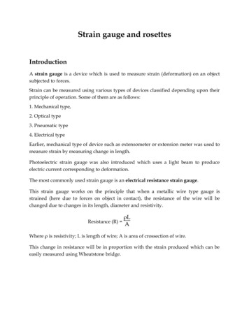
PRACTICAL STRAIN GAGE MEASUREMENTSSTRAIN GAGESFigure 12: Foil BondedResistance Strain Gagestransmit strain from the specimen tothe grid. They also act as anelectrical insulator between the gridand the specimen and must transferheat away from the grid. Threeprimary factors influencing gageselection are 1) operatingtemperature; 2) state of strain(including gradients, magnitude andtime dependence); and 3) stabilityrequirements for the gageinstallation. The importance ofselecting the proper combination ofcarrier material, grid alloy, adhesive,and protective coating for the givenapplication cannot be overemphasized. Strain gagemanufacturers are the best sourceof information on this topic and havemany excellent publications toassist the customer in selecting theproper strain gages, adhesives andprotective coatings.E-102GAGE FACTORWhen a metallic conductor isstrained, it undergoes a change inelectrical resistance, and it is thischange that makes the strain gagea useful device. The measure of thisresistance change with strain isGAGE FACTOR, GF. Gage factor isdefined as the ratio of the fractionalchange in resistance to thefractional change in length (strain)along the axis of the gage. GageE
PRACTICAL STRAIN GAGE MEASUREMENTSfactor is a dimensionless quantity,and the larger the value, the moresensitive the strain gage. Gagefactor is expressed in equationform as:Gage LengthGF R/R R/R L/L End LoopsTransitionOverall Pattern LengthSolder Tab LengthTab SpacingGrid WidthEquation No. 10It should be noted that the change inresistance with strain is not duesolely to the dimensional changes inthe conductor, but that the resistivityof the conductor material alsochanges with strain: The term gagefactor applies to the strain gage as awhole, complete with carrier matrix,not just to the strain-sensitiveconductor. The gage factor forConstantan and nickel-chromiumalloy strain gages is nominally 2,and various gage andinstrumentation specifications areusually based on this nominal value.Solder Tab WidthGrid CenterAlignment MarksOuter Grid LinesFigure 13: Strain Gage Nomenclaturetransverse direction.TRANSVERSE SENSITIVITYFACTOR, Kt, is defined as:Kt GF (transverse)GF (longitudinal)and is usually expressed in percent.Values of K range from 0 to 10%.TRANSVERSESENSITIVITYif the strain gage were a singlestraight length of conductor of smalldiameter with respect to its length, itwould respond to strain along itslongitudinal axis and be essentiallyinsensitive to strain appliedperpendicularly or transversely tothis axis. For any reasonable valueof gage resistance, it would alsohave a very long gage length. Whenthe conductor is in the form of a gridto reduce the effective gage length,there are small amounts of strainsensitive material in the end loops orturn-arounds that lie transverse tothe gage axis. See Figure 13. Thisend loop material gives the gage anon-zero sensitivity to strain in theInner Grid LinesTo minimize this effect, extramaterial is added to the conductorin the end loops, and the grid linesare kept close together. This servesto minimize resistance in thetransverse direction. Correction fortransverse sensitivity may benecessary for short, wide-gridgages, or where there isconsiderable misalignment betweenthe gage axis and the principal axis,or in rosette analysis where hightransverse strain fields may exist.Data supplied by the manufacturerwith the gage can be entered intothe computer that controls theinstrumentation, and corrections fortransverse sensitivity can thus bemade to the strain data as it iscollected.E-103TEMPERATUREEFFECTSIdeally, we would prefer the straingage to change resistance only inresponse to stress-induced strain inthe test specimen, but the resistivityand strain sensitivity of all knownstrain-sensitive materials vary withtemperature. Of course this meansthat the gage resistance and thegage factor will change when thetemperature changes. This changein resistance with temperature for amounted strain gage is a function ofthe difference in the thermalexpansion coefficients between thegage and the specimen and of thethermal coefficient of resistance ofthe gage alloy. Self-temperaturecompensating gages can beproduced for specific materials byprocessing the strain-sensitive alloyin such a way that it has thermalresistance characteristics thatcompensate for the effects of themismatch in thermal expansioncoefficients between the gage andthe specific material. A temperaturecompensated gage produced in this
PRACTICAL STRAIN GAGE MEASUREMENTSFigure 14: Typical Temperature-Induced Apparent StrainAPPROXIMATE THERMALEXPANSION COEFFICIENTMATERIALPPM/ CQuartz0.5Titanium9Mild Steel11Stainless Steel16Aluminum23Magnesium26Table 2: Thermal Expansion Coefficientsof Some Common Materials for WhichTemperature Compensated Strain GagesAre AvailableThe compensation is only effectiveover a limited temperature rangebecause of the nonlinear characterof both the thermal coefficient ofexpansion and the thermalcoefficient of resistance.THE MEASUREMENTFrom the gage factor equation, wesee that it is the FRACTIONALCHANGE in resistance that is theimportant quantity, rather than theabsolute resistance value of thegage. Let’s see just how large thisresistance change will be for a strainof 1. If we use a 120 Ω straingage with a gage factor of 2, the gage factor equation tells usthat 1applied to a 120 Ω gageproduces a change in resistance of R 120 x 0.000001 x 2 0.000240 ΩE-104or 240 micro-ohms. That means weneed to have micro-ohm sensitivityin the measuring instrumentation.Since it is the fractional change inresistance that is of interest, andsince this change will likely be onlyin the tens of milliohms, somereference point is needed fromwhich to begin the measurement.The nominal value of gageresistance has a toleranceequivalent to several hundredmicrostrain, and will usually changewhen the gage is bonded to thespecimen, so this nominal valuecan’t be used as a reference.An initial, unstrained gageresistance is used as the referenceagainst which strain is measured.Typically, the gage is mounted onthe test specimen and wired to theinstrumentation while the specimenis maintained in an unstrained state.STRAIN GAGESmanner is accurately compensatedonly when mounted on a materialthat has a specific coefficient ofthermal expansion. Table 2 is a listof common materials for which selftemperature-compensated gagesare available.E
PRACTICAL STRAIN GAGE MEASUREMENTSA reading taken under theseconditions is the unstrainedreference value, and applying astrain to the specimen will result in aresistance change from this value. Ifwe had an ohmmeter that wasaccurate and sensitive enough tomake the measurement, we wouldmeasure the unstraine
directly measurable. Strain of this type is also often referred to as normal strain. SHEARING STRAIN Another type of strain, called SHEARING STRAIN, is a measure of angular distortion. Shearing strain is also directly measurable, but not as easily as normal strain. If we had a thick book