Transcription
Introduction to Solar CoolingSystemsCourse No: R02-002Credit: 2 PDHJ. Paul Guyer, P.E., R.A., Fellow ASCE, Fellow AEIContinuing Education and Development, Inc.9 Greyridge Farm CourtStony Point, NY 10980P: (877) 322-5800F: (877) 322-4774info@cedengineering.com
An Introductionto Solar CoolingSystemsGuyer Partners44240 Clubhouse DriveEl Macero, CA 95618(530)7758-6637jpguyer@pacbell.net J. Paul Guyer 2010J. Paul Guyer, P.E., R.A.Paul Guyer is a registered civil engineer,mechanical engineer, fire protection engineer,and architect with over 35 years experience inthe design of buildings and relatedinfrastructure. For an additional 9 years hewas a senior advisor to the CaliforniaLegislature on infrastructure and capital outlayissues. He is a graduate of Stanford Universityand has held numerous national, state andlocal positions with the American Society ofCivil Engineers and National Society ofProfessional Engineers.1
This course is adapted from the Unified Facilities Criteria of the United States government,which is in the public domain, has unlimited distribution and is not copyrighted. J. Paul Guyer 20102
CONTENTS1. INTRODUCTION2. ABSORPTION COOLING3. RANKINE CYCLE HEAT ENGINE COOLING4. DESICCANT COOLING5. OTHER COOLING METHODS6. ESTIMATING SYSTEM SIZE7. SYSTEM CONTROLS8. PIPING, PUMPS, VALVES9. COLLECTORS10. OTHER CONSIDERATIONS J. Paul Guyer 20103
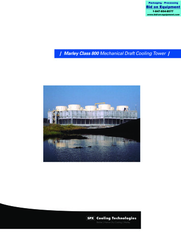
1. INTRODUCTION. The state-of-the-art of solar cooling has concentrated primarilyon the developmental stages of systems in the last few years. Various methods havebeen researched, and some demonstrated, but only a few systems have been installedfor other than research purposes. Solar cooling systems are attractive because coolingis most needed when solar energy is most available. If solar cooling can be combinedwith solar heating, the solar system can be more fully utilized and the economic benefitsshould increase. Solar cooling systems by themselves, however, are usually noteconomical at present fuel costs. Combining solar heating and cooling systems is noteasy because of the different system requirements. This can best be understood bysummarizing the different solar cooling techniques. As with solar heating, thetechniques for solar cooling consist of passive systems and active systems. Thepassive systems are not part of this course. For active solar cooling systems the threemost promising approaches are the heat actuated absorption machines, the Rankinecycle heat engine, and the desiccant dehumidification systems. A brief summary ofthese systems is given here and a more detailed explanation can be found in othersources in the literature.2. ABSORPTION COOLING. Absorption cooling is the most commonly used method ofsolar cooling. An absorption refrigeration machine is basically a vapor-compressionmachine that accomplishes cooling by expansion of a liquid refrigerant under reducedpressure and temperature, similar in principle to an ordinary electrically operated vaporcompression air conditioner. Two refrigerant combinations have been used: lithiumbromide and water, and ammonia and water. There have been a number of proposedsolid material absorption systems also. Figure 1 shows a typical lithium bromide (LiBr)absorption cooler. In the absorption cooler, heat is supplied to the generator in which arefrigerant is driven from a strong solution. The refrigerant is cooled in the condenserand allowed to expand through the throttling valve. The cooled, expanded refrigerantreceives heat in the evaporator to provide the desired cooling, after which the refrigerantis reabsorbed into the cool, weak solution in the absorber. The pressure of the resultingstrong solution is increased by pumping and the solution is available to repeat theprocess. J. Paul Guyer 20104
Figure 1Schematic of Lithium Bromide Absorption CoolerThe performance of the system is governed largely by the temperature differencebetween the generator and the condenser and absorber units. Since the generatortemperatures in solar driven systems are only moderate, it is important to keep thecondenser and absorber temperatures as low as possible. The LiBr system is preferredover ammonia systems for solar energy applications because of the lower generatortemperatures required. Permissible generator temperatures for a water-cooled LiBrsystem range from 170 deg. F to 210 deg. F (76 deg. C-99 deg. C) compared to the 205deg. F to 248 deg. F (95 deg. C-120 deg. C) temperatures required for a water-cooledammonia absorption system. Most, if not all, of the commercially available absorptionunits use LiBr and water as the absorbent-refrigerant fluid pair. Because the LiBr willcrystallize at the higher absorber temperatures associated with air cooling, these unitsmust be water cooled. A prototype ammonia-water unit, amenable to direct air cooling,has been built by Lawrence Berkeley Laboratories. J. Paul Guyer 20105
A number of equipment requirements and limitations must be considered in the analysisand design of solar powered absorption systems. The first consideration involves thetype of collector used. The temperatures required by absorption coolers are obtainablewith flat plate collectors but at low collection efficiencies. Collection efficiency isimproved with an increased number of glazings and with a selective surface, therefore,it may be cost effective to improve the collector rather than to simply oversize.Concentrating or evacuated tube collectors are usually used in these applications. Ifconcentrating collectors are used, the associated higher costs and potentially increasedmaintenance for the tracking mechanism must be considered. In general, concentratingcollectors operate at higher efficiency at these higher temperatures. However, thehigher temperatures are usually not required to operate the space heating system.Therefore, the relative importance of the two thermal loads must be considered whenselecting a system. The second consideration involves the means of delivery of theheated fluid to the absorption cooler. Since, in many climates, the cooling load issimultaneous with and often proportional to the solar insolation, it may be desirable toallow the heated collector fluid to bypass the storage unit. Other climates may require ahot storage unit but one of considerably smaller size than the one used for heatingpurposes. The important requirement is that high temperatures be available duringperiods of heavy cooling load. A third consideration deals with the problem of reducedefficiency of the absorption cooler under start up and transient conditions. Typicalabsorption coolers do not reach operating efficiency until after an hour or more ofoperation time. A machine which is cycled on and off regularly will have a drasticallyreduced average coefficient of performance when compared to a machine in steadystate performance. This problem has been overcome in at least one installation by theuse of a cold storage unit. The cold storage unit permits continuous operation of theabsorption cooler and thus allows some reduction in the system and cooler size.A fourth consideration is the need for some means of cooling the absorber and thecondenser. A cooling tower or some other low temperature cooling system must beused to obtain reasonable performance. All of the commercially available units require acooling tower which is another maintenance item. Current research is underway todevelop units that do not have a separate cooling tower. J. Paul Guyer 20106
3. RANKINE CYCLE HEAT ENGINE COOLING. Rankine cooling systems are still indevelopment with only a few in operations. In these systems the shaft power producedby a heat engine drives the compressor in a conventional vapor compression-typecooling machine. The thermal energy input to the heat engine can be from a solarcollector or from a solar collector and a fossil fuel combustor. The fossil fuel cansupplement solar energy, or it can be used alone as the auxiliary energy supply whenno solar energy is available. Alternatively, electricity can be used as the auxiliary energysupply by coupling an electric motor directly to the compressor shaft. Another option is amotor-generator using a heat engine for generating electricity when solar energy isavailable and there is little or no cooling load.From state-of-the-art considerations, two types of fluid heat engines are primarilyfeasible in solar cooling units. In one type of engine, the working fluid cyclically changesphase from liquid to gas and back to liquid. The most widely used engine of this typeoperates on the Rankine cycle. In the other type, the working fluid remains in thegaseous state. These engines operate on various cycles, including the Stirling andBrayton cycles. For relatively low thermal energy input temperatures (less than 400deg. F), Rankine cycle engines are superior in performance to gas cycle engines. Athigher temperatures, gas cycle engines equal or better the performance of Rankinecycle engines.Relatively low temperatures are attainable with state-of-the-art thermal solar collectors,so the heat engine-vapor compression development projects involve Rankine cycleengines. In a Rankine cycle engine, fluid in the liquid state is pumped into a boilerwhere it is evaporated and possibly superheated by thermal energy. The vaporgenerated in the boiler is then expanded through a device such as a turbine, a pistoncylinder (reciprocating) expander, or a rotary vane expander. The expansion processlowers the temperature and pressure of the vapor, and effects a conversion of thermalenergy into shaft work. The fluid leaves the expander either in the vapor phase or as aliquid-vapor mixture and flows into a condenser, where it returns to the liquid phase bygiving the energy of condensation to cooling water or ambient air. This liquid is then J. Paul Guyer 20107
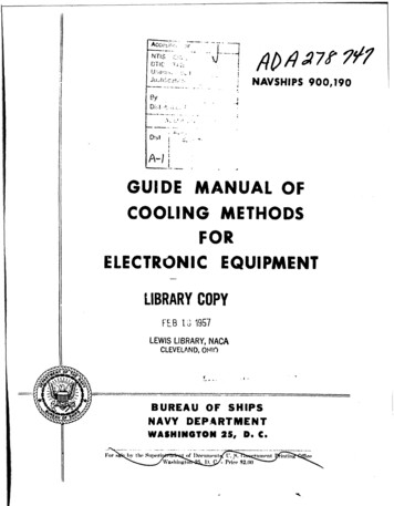
pumped into the boiler, and the cycle is repeated. In some systems underdevelopment, the same working fluid is used in both the Rankine engine and the vaporcompression chiller, which permits the use of common condenser and the elimination ofspecial seals to maintain fluid separation in the expander-compressor unit. Thesesystems have areas that need development in matching the solar heat engine with themechanical compressor units of the cooling equipment. Since most compressors aredesigned for certain speed and torque inputs, the varying operation of a solar heatengine will probably reduce the overall coefficient of performance (COP) of the unit.Also the solar heat engine is at high efficiency at high storage tank temperatureswhereas the solar collectors are at low efficiency which will also affect the COP of thesystem. These systems are designed for large cooling load applications.4. DESICCANT COOLING. The Rankine engine vapor compression and the absorptioncooling units operate on the basis of closed cycles-fixed amounts of working fluid arecirculated within sealed equipment; the working fluids do not come in contact with thebuilding air. Desiccant cooling systems, on the other hand, may be designed for opencycle operation, since the only circulating fluids involved are air and water. The basicconcept is to dehumidify air with a desiccant, evaporatively cool the dehumidified air,and regenerate the desiccant with solar-derived thermal energy.Two basic open-cycle arrangements are feasible: the ventilation mode and therecirculation mode. In the ventilation mode, fresh air is continually introduced into theconditioned space. In the recirculation mode, exhaust air from the conditioned space isreconditioned and returned to the space. Figure 2 illustrates a ventilation system inwhich a solid desiccant material mounted on a slowly rotating wheel provides the basisfor obtaining a cooling effect. The hot desiccant material absorbs moisture fromincoming ventilation air and increases the dry-bulb temperature. This dry air stream iscooled in two steps. First, it is sensibly cooled by heat exchange with the buildingexhaust air. Then it is evaporatively cooled and partially rehumidified by contact with awater spray. The exhaust air from the building is evaporatively cooled to improve the J. Paul Guyer 20108
Figure 2Schematic of Solar Desiccant Coolingperformance of the heat exchanger. After being heated by heat exchange with theincoming air, the exhaust air is further heated by energy from the solar system and/orfrom an auxiliary energy source. The hot exhaust air passes through the desiccantmaterial and desorbs moisture from it, thereby regenerating it for continuation of theprocess. Desiccant systems have faced problems of high parasitic power and largespace requirements relative to capacity. Because of their bulkiness, the systems mayhave primary application in the low capacity range (i.e., residential systems) if and whenways can be found to reduce parasitic power requirements to acceptable levels.The Institute of Gas Technology (IGT) has been investigating design modifications in aprototype 3-ton system. AiResearch is developing a 1-l/2-ton desiccant cooling systemaround a radial flow design. Illinois Institute of Technology is developing a dehumidifierof a cross-flow design that will provide more compact and efficient operation than J. Paul Guyer 20109
previous designs. Zeopower is developing a unique closed cycle desiccant system inwhich the desiccant is integral with the collector.5. OTHER COOLING METHODS. Other methods, using solar heating equipment butnot direct solar energy, should also be considered. These methods chill the thermalstorage unit of the system during the night and use the chilled medium to provide thedaily cooling load. Methods of chilling the storage include radiation of the heat to thenight sky and heat exchange with the night air cooled or uncooled by auxiliary means.The chilled storage is used directly, via heat exchange with the building air. Bothrockbed and water storage are suitable since the only additional hardware required isthat to route the fluid. A heat pump can be used during the day to cool the building andreject heat to the thermal storage unit. The thermal storage is then cooled by using thesolar collectors for night sky radiation. From experimentation in Arizona, Bliss obtaineda nightly heat rejection quantity of 360 Btu/night/ft2 for a black cloth radiator. Analyticalestimates can be obtained using an effective clear sky temperature of 25 deg. F (14deg. C) lower than the ambient air temperature. The advantage of this system is that thesame equipment (collectors and heat pump) can also be used for heating. In systemswith dual storage units, the heat pump transfers heat from one to the other - cooling thefirst and warming the second. The cool fluid in the first unit is circulated to the housewhile the concentrated heat in the second is discharged to the outdoors. Anevaporative cooler can be used coupled with a rockbed storage unit. Night air isevaporatively cooled and circulated through the rockbed to cool down the pebbles in thestorage unit. During the day, warm air from the building can be cooled by passing itthrough the cool pebble bed. This method is not very effective in humid geographicalareas.The storage volume can also be cooled using a small refrigeration compressor. Mostthrough-the-wall air conditioners use such compressors to cool the indoor air. This unitacts as the backup or auxiliary cooling system - analogous to the backup heatingsystem. If operated only at night, its capacity can be as small as half that of anindependently functioning unit and still meet peak cooling demands. Nighttime operation J. Paul Guyer 201010
will be particularly wise if electric companies charge more for electricity during times ofpeak loads on hot summer afternoons. An even smaller compressor can be used if itoperates continuously night and day - cooling the storage when not needed by thehouse.6. ESTIMATING SYSTEM SIZE. The sizing of cooling system components isdependent on hardware, climate, and economic constraints. The cooling unit must besized so as to provide the maximum cooling load under conceivable adverse conditionsof high humidity and low or erratic solar insolation. The collection area required isdependent on the fraction of the cooling load to be provided by solar. Very largecollector areas may be required for 100% solar cooling under adverse conditions of highhumidity and low insolation. Although a detailed calculation method is not available forsolar cooling, an estimate of the required collector area can be made by the equation:In general, the collector area required to provide the majority of the cooling load is largerthan the collector area of typically sized heating only systems. Collector areas for heatengine systems are larger than the areas for absorption cooling systems due to thethermal efficiency of the heat engine, which should be included in the precedingequation. J. Paul Guyer 201011
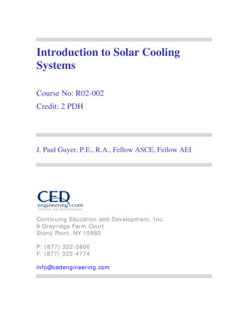
7. SYSTEM CONTROLS. System controls are used to turn on a circulating pump orblower to the collector only when the sun is providing heat. Differential thermostats arecommercially available to turn on the collector pump only when the collector platetemperature is a preset number (usually 20 deg. F) hotter than the storage tank bottomtemperature. A typical control strategy is shown in Figure 3 and the hookup in Figure 4.Differential thermostats are available with high temperature protection and lowtemperature (freeze) protection. High temperature protection is important, especially inevacuated tube collectors, in that it prevents a very "hot" collector from suddenlyreceiving a supply of cold water thus producing a thermal shock that could damage thecollector components. Another type of control called proportional control is available. Itis similar to the ON/OFF differential controller in operation. The difference is that theproportional controller changes the threshold ON and OFF points and controls the flowsuch that less than full flow can be achieved if the sun is at less than full intensity. Theadvantage is that the proportional control can "turn on" the system when the othercontroller (the ON/OFF type) is waiting for more sun to become available. This is anadvantage on cloudy days and early morning start ups. Overall system efficiency isincreased slightly with the proportional control. These controls are more expensive andone such experiment at NCEL has shown that proportional controls result inconsiderably more cycling of the pump motor which could shorten pump life. It isrecommended that the control manufacturer be consulted on this point before aproportional control is used. As the building requires heat, other controls must directpumps or blowers to provide heat from the storage tank to the load. This control is theconventional thermostat. The same room thermostat may control the auxiliary heater;however, a delay timer or a two-step room thermostat must be incorporated into theauxiliary heater control circuit so that the auxiliary heat will not come on if heat isavailable from storage. Ten minutes has been suggested as a typical time delay before J. Paul Guyer 201012
Figure 3Control System StrategyFigure 4Control System for Space Conditioning and Domestic Hot Water (DHW) J. Paul Guyer 201013
auxiliary heat comes on. Some manufacturers supply combination thermostat and solarsystem controls.8. PIPING, PUMPS, VALVES8.1 PIPE AND HEADER SIZING. Piping should be designed for low pressure drop. Allexposed piping should be well insulated with approved weather-resistant insulation.Dielectric unions should be used at connections between dissimilar metals. Rubber orsilicone hose used for connections must be of a high temperature type. The pipe endsshould have ferrules to provide a good seal with the hose. In low pressure systems,spring type clamps are preferred because they compensate for thermal expansion.Copper pipe is preferred to galvanized steel due to its longer life expectancy andrelative ease of installation. Thermal expansion should be provided for all piping or hardtubing. Pipe sizing should be in accordance with recognized methods, but for mostinstallations the following estimates are reasonable:8.1.1 FOR A SINGLE ROW OF PARALLEL COLLECTORS WITH "X" NUMBER OFBRANCHES 0.5 gpm flow per collector, water or 50% glycol as heat transfer fluid. Up to 3 collectors - 1/2-inch headers 4 to 7 collectors - 3/4-inch headers 8 to 12 collectors - 1-inch headers 13 to 18 collectors - 1-1/4-inch headers More than 19 collectors - 1-1/2-inch or larger (size for each design)8.1.2 SAME AS ABOVE EXCEPT COLLECTORS IN A DOUBLE ROW SERIESPARALLEL ARRANGEMENT Up to 5 collector branches - 1/2-inch headers 6 to 10 collector branches - 3/4-inch headers 11 to 15 collector branches - 1-inch headers J. Paul Guyer 201014
16 to 22 collector branches - 1-1/4-inch headers More than 23 collectors - 1-1/2-inch or larger (size for each design)8.2 PUMPS AND COLLECTOR FLOWRATE. Pumps are sized in accordance withrecognized practices also. Since solar systems are nothing more than a combination ofpipes, valves, and fittings it is possible to do a heat loss calculation to determine thesystem head. Charts are available in standard fluid flow handbooks that give the frictionlosses or "equivalent length of feet in pipe" for various fittings and valves. These aremerely summed for the entire system. The flowrate through the collector loop isdetermined by the maximum amount of energy which must be removed from thecollector. This maximum is about 225 Btu/ft 2 /hr. Often a manufacturer will specify theflowrate through his collector and this value should be used. If not, an estimate can bemade by determining the flowrate necessary to remove the maximum amount of energywhile minimizing the collector inlet temperature (to maintain high collector efficiency).The rule of thumb for this calculation is 0.015 to 0.020 gpm for each square foot ofcollector area for water. For other fluids this can be scaled by the value of the specificheat of the fluid as compared to water (Cp 1 Btu/lbm-deg. F). Now that head loss andflowrate are determined, a pump can be selected by using the manufacturers' standardtables and graphs. For typical domestic hot water systems and space heating systemsfor a house for a family of four, the pumps are quite small, averaging 1/12 to 1/20 hp. Insome systems, like a drain down system, pump sizes can be much larger due to thehigher vertical "head" requirements. If the water in the system is open to theatmosphere or if the water is to be used for drinking the pump should be made ofbronze or stainless steel on all water-wetted surfaces to minimize corrosion. Pumps willhave longer life if they are placed in low temperature parts of the water circuits. Pumpscan be "staged" to give more flow or head. Two pumps in series will give the same flowagainst twice the head. Two pumps in parallel will give twice the flow at the same head.Two or more small circulator-type pumps are often cheaper than a single larger pump.8.3 VALVES. Valves, other than seasonal or emergency shut-off valves, should beelectrically operated and located out of the weather or well protected. A vent must be J. Paul Guyer 201015
provided at the high point in liquid systems to eliminate entrapped air and it should alsoserve as a vacuum breaker to allow draining of the system. To avoid multiple venting,systems should be piped to avoid having more than one high point. Pressure relief mustbe provided at some point in each flow circuit. Check valves can be added to preventthermally induced gravity circulation. A flow-check valve (used in the hydronic heatingindustry) will also accomplish the same purpose. Mixing valves should be used toprotect DHW systems from delivering water hotter than specified (usually 120 deg. - 140deg. F). Consideration should be given to energy conservation by lowering DHWtemperature whenever possible. Often 105 deg.-115 deg. F will suffice if water is usedonly for showers and washing hands.9. COLLECTORS. The collector is the most important and one of the most expensiveparts of a solar system. It must be long-lived and well insulated, yet its cost must beminimized. Collectors of primary interest are of two basic types: liquid and air. Liquidsmay be water, an antifreeze mixture, or various hydrocarbon and silicone heat transferoils. Air-type collectors use air as the collector fluid. The absorber plate is that part ofthe collector which absorbs the solar energy and converts it to thermal energy. A portionof the thermal energy is carried to the building or thermal storage unit by the fluid whichcirculates through passages in the absorber plate. The absorber plates can be made ofmetal, plastic, or rubber compounds. The metals commonly used in order of decreasingthermal conductivity are copper, aluminum, and steel. Plastics (polyolefins) and rubbers(ethylene propylene compounds) are relatively inexpensive, but due to their low thermalconductivity and their temperature limitations, they are suitable only for low temperatureapplications, such as heating swimming pool water or for use with water source heatpumps. Other major components of a solar collector include: Absorber plate coating - To enhance the heat transfer and protect the absorberplate. One or more transparent covers - To reduce thermal losses by radiation (usingthe "greenhouse effect") and by convection (wind, etc.). Spacings are nominally1/2 inch or more. J. Paul Guyer 201016
Insulation - One to three inches are used to reduce heat loss through the sideand back of the absorber plate. Collector box or housing - To provide a rigid mounting to hold the components.Must be weatherproofed. Gaskets and seals - To insure a weathertight seal between components whileallowing thermal expansion of the components. Normally these seals remainductile to accomplish their purpose.Flat-plate collectors are most suitable for low temperature applications such asdomestic hot water and space heating. They collect both direct and diffuse radiation. Itis not required that they track the sun, thus initial cost and maintenance are minimized.A properly designed flat-plate collector has a life expectancy of 10 to 25 years, orsometimes longer. All copper and glass systems currently exhibit the longest lives.Using softened water will help. Tubes should be 1/2 inch in diameter or greater for lowpressure drop and longer life. The better the attachment of tube-to-plate (such as bysoldering), the better the heat transfer, but the greater the manufacturing cost.Advances in collector cost reduction will probably be made in the direction of cheapermanufacturing processes. Some collectors not made from tube and sheet may nottolerate DHW line pressures. Specifications for pressurized collector circuits shouldrequire collectors which will take proof test pressure equal to 150% of expected circuitpressure. In hot climates, it is important to reduce roof heat load due to collector heatgain in summer; this can be accomplished by venting the space between collector plateand glazes with dampers or by covering the collectors. A normal amount of dirt and duston the glass cover will reduce heat collected by about 5%. Normal rainfall is usuallysufficient to relieve this problem. Except for warm climates with high insolation (I / 1400 Btu/ft2-Day), two cover glasses may be optimum. In warm climates, one glass isoptimum. Many plastics have an undesirable transparency to infrared radiation, to whichglass is nearly opaque, so the desired "greenhouse effect" is not so pronounced withplastic materials as with glass. However, losses by radiation from the collector are smallcompared with convective losses due to wind; thus plastics can be employed to reducebreakage and cost, but with some loss in collector performance. Plastics with maximum J. Paul Guyer 201017
opaqueness to infrared and maximum transparency to ultraviolet (UV) and visibleradiation and with high resistance to UV degradation should be specified. The followingsections give more detailed information on collector designs and components.9.1 LIQUID AND AIR-TYPE COLLECTORS. Liquid types are more suited to domestichot water (DHW), the collector area is usually smaller, and more information is availableabout liquid systems. Collectors for heating air do not require protection from freezingand have minimal corrosion problems, leaks do not cause serious damage, they maycost less per unit area, and are better suited to direct space heating for residenceswhere duct-work is already present. However, since leaks in air systems are less easilydetected, they can degrade system performance if not corrected. Wherever this manualdiscusses liquid collectors, air collectors are included, and cost analyses apply equallyto both. The design procedure for air collectors differs, however. Heat transfer oils usedin liquid systems offer freeze protection and some corrosion protection, but they alsorequire heat exchangers for heating domestic hot water, as do antifreeze-watermixtures.9.2 SELECTIVE SURFACES. Some collectors are manufactured with a black coatingwhich absorbs the high frequency incoming solar radiation very well and which emitslow frequency infrared radiation poorly. This is a highly desirable combination ofproperties for a collector. The absorptance should be 0.9 or higher and emittance maybe 0.1 or lower. Such coatings are approximately equal in effect to one cover glass.Thus, a selective coating plus one cover glass may be expected to be about equal inefficiency to a collector with two cover glasses and a flat black painted surface.Electroplated black nickel, black chrome, copper oxide and anodized aluminum arecommon types of selective coatings. Cost of selective surface coatings may be greaterthan an extra sheet of glass, but much research is being done to produce low cost,easily applied coatings. The stability of black nickel, chrome and aluminum in
The state-of-the-art of solar cooling has concentrated primarily on the developmental stages of systems in the last few years. Various methods have been researched, and some demonstrated, but only a few systems have been installed for other than research purposes. Solar cooling systems are attractive because cooling