Transcription
Another EMC resourcefrom EMC StandardsEMC techniques in electronic design Part 4 - Shielding(screening)Helping you solve your EMC problems9 Bracken View, Brocton, Stafford ST17 0TFT: 44 (0) 1785 660247E:info@emcstandards.co.uk
Design Techniques for EMCPart 4 — Shielding (screening)Originally published in the EMC Compliance Journal in 2006-9,and available from Eur Ing Keith Armstrong CEng MIET MIEEEPartner, Cherry Clough Consultants, www.cherryclough.com, Member EMCIA, EMCTLAPhone/Fax: 44 (0)1785 660247, Email: keith.armstrong@cherryclough.comThis is the fourth in a series of six articles on basic good-practice electromagnetic compatibility (EMC)techniques in electronic design, to be published during 2006-7. It is intended for designers of electronicmodules, products and equipment, but to avoid having to write modules/products/equipment throughout –everything that is sold as the result of a design process will be called a ‘product’ here.This series is an update of the series first published in the UK EMC Journal in 1999 [1], and includes basic goodEMC practices relevant for electronic, printed-circuit-board (PCB) and mechanical designers in all applicationsareas (household, commercial, entertainment, industrial, medical and healthcare, automotive, railway, marine,aerospace, military, etc.). Safety risks caused by electromagnetic interference (EMI) are not covered here; see[2] for more on this issue.These articles deal with the practical issues of what EMC techniques should generally be used and how theyshould generally be applied. Why they are needed or why they work is not covered (or, at least, not covered inany theoretical depth) – but they are well understood academically and well proven over decades of practice. Agood understanding of the basics of EMC is a great benefit in helping to prevent under- or over-engineering, butgoes beyond the scope of these articles.The techniques covered in these six articles will be:1)2)3)4)5)6)Circuit design (digital, analogue, switch-mode, communications), and choosing componentsCables and connectorsFiltering and suppressing transientsShielding (screening)PCB layout (including transmission lines)ESD, surge, electromechanical devices, power factor correction, voltage fluctuations, supply dips anddropoutsMany textbooks and articles have been written about all of the above topics, so this magazine article format cando no more than introduce the various issues and point to the most important of the basic good-practice EMCdesign techniques. References are provided for further study and more in-depth EMC design techniques.Table of contents for this article4.Shielding (screening) .24.1 Introduction . 24.2 Shielding with metal plates . 44.3 Volumetric shielding of products. 54.3.1 Nested shielding and cost-of-manufacture. 54.3.2 General concepts in volumetric shielding. 64.3.3 Skin effect and absorption. 84.3.4 Very low frequency shielding. 94.3.5 SE is compromised by leakage from apertures . 94.3.6 The resonant/antenna behaviour of a single aperture in the far field. 104.3.7 Multiple apertures in the far field . 134.3.8 Cavity resonances and aperture leakage. 144.3.9 Near-field leakages through apertures. 164.3.10 Designing to reduce aperture leakages . 174.3.11 Waveguide-below-cutoff techniques. 21Design Techniques for EMC – Part 4 Cherry Clough Consultants May 2009Page 1 of 68
4.44.54.64.74.84.94.3.12 Shielding of displays (and the like) . 274.3.13 Shielding membrane switch panels . 314.3.14 Shielding ventilation apertures. 314.3.15 Shielding rotating metal shafts that penetrate an enclosure. 324.3.16 Combining heatsinking with enclosure shielding . 324.3.17 Preventing shield degradation from conductor penetrations . 33Shielding at PCB level . 354.4.1 Reasons for shielding at PCB level . 354.4.2 Overview of techniques for PCB level shielding. 364.4.3 Types of PCB shielding-can . 384.4.4 Methods for bonding shielding-cans to PCB planes . 394.4.5 Suitable materials for PCB shielding-cans . 404.4.6 Apertures in PCB shielding-cans. 404.4.7 Waveguide-below-cutoff methods in PCB-level shielding. 414.4.8 Cavity resonances in PCB shielding-cans . 424.4.9 Shielded cables and traces entering/exiting PCB shielding-cans . 444.4.10 Combining filtering with shielding at PCB level. 464.4.11 Combing heatsinking with shielding at PCB level. 47Estimating shielding effectiveness with PC-based simulators. 48EMC gaskets. 494.6.1 Volume-conductive elastomers . 494.6.2 Conductively coated or wrapped elastomers, see Figure 4BH . 514.6.3 Metal (wire) meshes, see Figure 4BJ. 524.6.4 Spring fingers (‘finger stock’), see Figure 4BK. 524.6.5 Some other types of gaskets. 544.6.6 Mechanical design techniques for gaskets . 554.6.7 Gasket clamping. 58Materials useful for shielding . 584.7.1 Metals and their surface finishes. 584.7.2 The problems of polymer passivation. 594.7.3 Metallised papers and fabrics. 604.7.4 Paints and lacquers. 614.7.5 Painted or plated plastics . 614.7.6 Shielding with volume-conductive plastics . 634.7.7 Alternatives to shielding plastic enclosures. 634.7.8 Environmental considerations . 634.7.9 Preventing corrosion . 64References. 66Acknowledgements. 684.Shielding (screening)4.1IntroductionShielding is used to attenuate unwanted frequencies travelling through the air, or through whatever the productis immersed within (e.g. vacuum, oil, etc.) – and shields are characterised by attenuation versus frequencycurves. In many ways, electromagnetic (EM) shields are the radiated-wave equivalents of EM filters, whichattenuate conducted EM waves (see Part 3 of this series [3]). As will be shown later, and was discussed insection 3.3.3 of [3], shielding and filtering generally have to be used together, in order for either one to providethe EMC benefits required.This article uses the word ‘shield’ instead of ‘screen’, because screen has some other common uses inelectronics (e.g. display screen). Cable shielding was dealt with in section 2.6 of [4], so this article is concernedwith other types of shields. Note that for cable shielding to function well, especially at frequencies above100MHz, the equipment connected to either end of the shielded cable also needs to be shielded, with its shieldbonded 360 to the cable shield.Design Techniques for EMC – Part 4 Cherry Clough Consultants May 2009Page 2 of 68
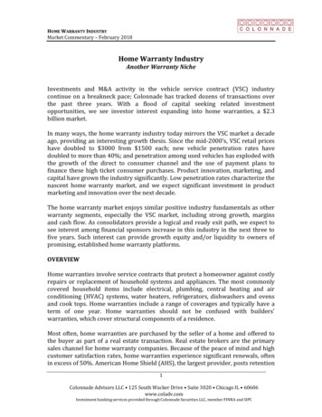
Figure 4A shows the radiated EM spectrum up to 2.5GHz, and some of its commonplace civilian uses. Thespectrum above 2.5GHz is being developed very quickly, as low-cost semiconductors that can operate at suchfrequencies are developed.dB0Taxicabs, walkie-talkies,private mobilemobile radio,radio, etc.etc.privateACsupplyradioFM radioBluetooth,Bluetooth,Wi-Fi, etc.CellphonesUHF TVCB radioradioCBwave radioradioShort wave-10Medium wavewaveMedium(AM radio)radio)(AM-20Long wavewaveLong(AM radio)-30Audio bandbandAudio-40-500.00001 0.00010.0010.010.1110100All thethe apparentlyapparently emptyempty regionsregions ofof thethe spectrumspectrum areare actuallyactually filledfilledAllby military,military, government,government, telecommunications and otherother licensedlicensed usersusersbyFigure 4A1,000MHzThe radiated spectrum and its uses (only up to 2.5GHz shown)Figure 4B shows the typical EM spectra of the noises radiated by some commonplace electronic devices, andan example of the radiated noise caused by sparking at an electrical contact. It is clear that to be able to usethe radiated spectrum for broadcasting, communications, etc., we must protect it from electronic and electricalnoise.Supply rectifiersrectifiersSupplyand theirtheir harmonicsharmonicsandpowerSwitch-mode powerconverters andand ssor clocksclocksMicroprocessorand theirtheir harmonicsand(this exampleexample 32MHz)32MHz)(this0-10-20-30-40noiseRandom noisefrom arcs andandfromsparks-500.00001 0.00010.0010.010.11101001,000MHzFigure 4BThe spectra of noises made by electrical/electronic devices (only up to 2.5GHz shown)Design Techniques for EMC – Part 4 Cherry Clough Consultants May 2009Page 3 of 68
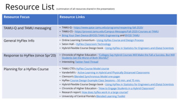
For the above reasons, shielding is a technique that has been used for many years, and Figure 4C shows partof a method for testing shielding effectiveness (SE) dating from 1882 (kindly provided by Anton Kohling ofSiemens EMC Test Laboratory in Erlangen).Figure 4CShielding Effectiveness testing in 1882Inadequately designed shielding-can make a product’s emissions or immunity worse than it was without theshield. One cannot, in general, simply select a shielded enclosure from a supplier’s catalogue and expect thatno more work will be required – there are numerous design and assembly techniques that need to be taken intoaccount if the purchased enclosure is to provide the shielding performance required. It is very easy tocompletely negate a shielded enclosure’s performance by not paying sufficient attention to the issues discussedin this article.Many textbooks and learned papers have been written on shielding and Chapter 34 of [5] includes a verycomprehensive list of them. There are also now a number of simulators that run on PCs and can be used tosimulate the effects of shields. This article will not go into wave equations and that sort of detail – instead it willdescribe the things that need to be taken into account so that shielding stands a good chance of performing asrequired, and to avoid unpleasant and/or costly experiences.Shielding design or selection is not a ‘black art’, but nevertheless it is difficult to predict
For the above reasons, shielding is a technique that has been used for many years, and Figure 4C shows part of a method for testing shielding effectiveness (SE)