Transcription
UPTEC F 14017Examensarbete 30 hpMaj 2014Improving efficiency of EMCImmunity Monitoring of RBS usinga FPGA based instrumentViktor Arfwedson
AbstractImproving efficiency of EMC Immunity Monitoring ofRBS using a FPGA based instrumentViktor ArfwedsonTeknisk- naturvetenskaplig orietLägerhyddsvägen 1Hus 4, Plan 0Postadress:Box 536751 21 UppsalaTelefon:018 – 471 30 03Telefax:018 – 471 30 00A test system for Immunity testing of Ericsson's LTE radio base station (RBS) wasbuilt using a National Instruments (NI) PXI chassis fitted with a vector signaltransceiver (VST) module and a PC controller module. A program made in LabVIEWand MATLAB was run on the controller module in the PXI chassis. The tasks of theprogram was, on one hand, to control the VST which was used to record the signalemitted from the RBS and on the other hand, to process the signal and determine itsquality by acquiring the bits transmitted. Functionality enabling the VST to transmit agiven signal was also included in the program. The built system performed up toninety times faster than the old system but lacked turbo decoding necessary tocorrectly determine bit error ratio (BER) and block error ratio (BLER). Theperformance of the system leaves room for adding time consuming processes such asturbo decoding later on and by examining the undecoded bits the signal quality canstill be measured. The program handles both 1tx and 2tx dledare: Patrik HellströmÄmnesgranskare: Mikael SternadExaminator: Tomas NybergISSN: 1401-5757, UPTEC F 14017
Improving e ciency of EMC ImmunityMonitoring of RBS using a FPGA basedinstrumentViktor ArfwedsonMay 12, 2014
Special thanks to:Patrik HellströmMikael SternadPeter BengtssonÖrjan Eriksson
SammanfattningEtt testsystem för immunitetstestning av Ericssons LTEradiobasstation (RBS) byggdes med ett PXI-chassi från National Instruments (NI) som bestyckades med en vector signaltranceiver (VST) modul och en PC-controller-modul. Ett program skapat i LabVIEW och MATLAB kördes på controllermodulen i PXI-chassit. Programmets uppgift var dels att kontrollera VST:n vilken användes för att spela in signalen somRBS:en sände ut och dels bearbeta den inspelade signalen ochavgöra dess kvalitet genom att ta fram de databitar som skickats. Funktionalitet för att låta VST:n sända en bestämd signal inkluderades även i programmet. Det byggda systemetpresterade upp till nittio gånger snabbare än det gamla systemet men saknade turboavkodning, något som är nödvändigtför att beräkna bitfelsratio (BER) och blockfelsratio (BLER) påett korrekt sätt. Programmets snabbhet lämnar utrymme föratt lägga till mer tidskrävande processer som turboavkodningvid ett senare tillfälle och genom att studera de icke avkodadedatabitarna kan signalens kvalitet fortfarande mätas. Programmet hanterar både 1 tx och 2 tx singaler.
AbstractA test system for Immunity testing of Ericsson's LTE radio base station (RBS) was built using a National Instruments(NI) PXI chassis tted with a vector signal transceiver (VST)module and a PC controller module. A program made in LabVIEW and MATLAB was run on the controller module in thePXI chassis. The tasks of the program was, on one hand, tocontrol the VST which was used to record the signal emittedfrom the RBS and on the other hand, to process the signal anddetermine its quality by acquiring the bits transmitted. Functionality enabling the VST to transmit a given signal was alsoincluded in the program. The built system performed up toninety times faster than the old system but lacked turbo decoding necessary to correctly determine bit error ratio (BER)and block error ratio (BLER). The performance of the systemleaves room for adding time consuming processes such as turbodecoding later on and by examining the undecoded bits the signal quality can still be measured. The program handles both1tx and 2tx signals.
Contents1 Introduction1.1 Thesis description . . . . . . . . . . . . . . . . .2 EMC Veri cation2.1 Immunity testing . .2.2 Current testbed . . . .2.2.1 Dwell time . .2.3 Planned testbed . . .2.3.1 Improvements .3.1 LabVIEW . . . . . . . . .3.1.1 Parallel execution3.1.2 Mathscript . . . .3.2 NI VST . . . . . . . . . .3.2.1 FPGA . . . . . . .4.1 OFDMA . . . . . . . . . . . . . . .4.2 Signal generation . . . . . . . . . .4.3 Downlink signal structure . . . . .4.3.1 Resource block . . . . . . .4.3.2 Signal components . . . . .4.3.3 Multiple Antenna Systems4.4 Downlink transport channel . . . .4.5 Data Acquisition . . . . . . . . . .5.1 Bit acquisition and error calculation (BaE) VI5.1.1 Turbo Decoding . . . . . . . . . . . . .5.1.2 G-code Version . . . . . . . . . . . . . .5.2 Performance . . . . . . . . . . . . . . . . . . .5.2.1 BaE VI execution . . . . . . . . . . . .5.2.2 Parallel execution . . . . . . . . . . . .3 NI PXI4 LTE5 Results6 Conclusions and open issues6.16.26.36.46.5Performance . . . . . . . . . . . . . .Turbo decoding implementation . . .NI PXI Chassis & VST . . . . . . . .Mathscript . . . . . . . . . . . . . . .Optimization . . . . . . . . . . . . . .6.5.1 Combinations of MATLAB and6.5.2 Run more things on the FPGA6.6 Implement looping . . . . . . . . . . .6.7 Inclusion into the testbed . . . . . . .6.7.1 Shorten test times . . . . . . .References. . . . . . . . . . . . . . . . . . . . .G-code. . . . . . . . . . . . . . . . 6373737373838383939393940404040415
Abbreviations16QAM16 Quadrature Amplitude Modulation64QAM64 Quadrature Amplitude ModulationASICApplication-speci c integrated circuitBERBit Error RatioBaEBit acquisition and Error calculationBLERBlock Error RatioBSBase StationDLDownlinkEMCElectromagnetic CompatibilityESDElectrostatic DischargeFDDFrequency-division duplexingFFTFast Fourier TransformFPGAField Programmable Gate ArrayHDLHardware description languageIFFTInverse Fast Fourier TransformLTELong Term EvolutionMIMOMultiple Input Multiple OutputNINational InstrumentsOFDMAOrthogonal Frequency Division Multiple AccessOFDMOrthogonal Frequency Division MultiplexingPCIPeripheral Component InterconnectPDSCHPhysical Downlink Shared ChannelPSSPrimary Synchronization SignalPXIPCI eXtensions for InstrumentationQPSKQuadrature Phase-Shift KeyRBSRadio Base Station (Ericsson terminology)RFRadio Frequency6
RSReference SignalRRURemote radio unitTBTransport BlockUEUser EquipmentUIUser InterfaceULUplinkVSTVector Signal TranceiverVIVirtual InstrumentVSGVector Signal GeneratorVSAVector Signal Analyzer7
Notation and symbolsf0Carrier frequencyTsSymbol time fSubcarrier spacingdSymbols to be transmitted in one subframeMsymbNumber of PDSCH symbols per subframexLayer mapped symbolsyPrecoded symbolsbBit sequencecScramble sequenceb̃Scrambled bit sequenceAMatrix containing all symbols in one frameAP DSCHMatrixA with zeroes on all non PDSCH resource elements8
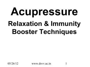
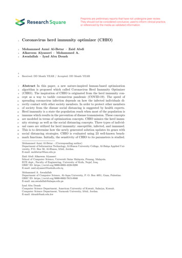
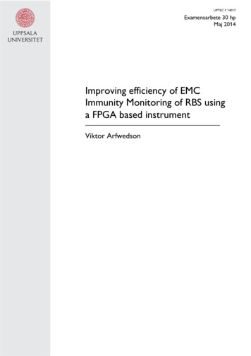
1 IntroductionBase stations make up the body of a wireless network and via antennasthey handle the direct communication with all mobile devices withinthe network.As more and more of our communication requires awireless connection increased coverage is of essence. A steady increasein speed and stability is also expected as people buy faster and moreadvanced phones.To keep up with growing demands the network infrastructure needsboth continuous expansions and upgrades. By creating a more widespreadnetwork, coverage can be achieved, by building a more dense networkspeed and stability can be achieved. Both solutions require more basestations. Higher speed can also be achieved by improving the way thephysical resources such as time and bandwidth is utilized. New standards like LTE (Long term evolution) improves the rate at which datacan be transferred via wireless connections.Upgrading networks tomeet these standards also require the production of new base stationsequipped with radios to handle both new and sometimes also olderstandards.All in all, new and better base stations are and will be in demandfor some time to come and this is what has made Ericsson one ofSweden's largest companies and a big player on the international telecom market with networks handling over 40 percent of world's mobiletra c. One of Ericsson's key products is their base station, the RBS(radio base station), which come in a number of varieties ranging fromsmall units with integrated antennas to larger cabinets containing upto twelve di erent radios. One of Ericsson's largest line of products isthe RBS 6000 series, an example of an RBS 6201 is shown in gure1. They are a common in many cities although not very noticeable,often placed in basements, on roofs or inside containers in close proximity to the antennas. In order for Ericsson to maintain its positionon the market, production needs to be fast and e ective. One important step of the production procedure is electromagnetic compatibility(EMC) veri cation testing which is performed to make sure that theRBS functions properly even under sub optimal radio frequency (RF)conditions.If EMC veri cation test times can be reduced withouta ecting the tests reliability there is pro t to gain not only by savingin on testing costs but also by speeding up production, thus makingthe products more competitive.1.1 Thesis descriptionThis thesis was performed at Ericsson's Integration and Veri cation(I&V) EMC unit. It focuses on improving the e ciency of the currenttest system for EMC veri cation tests for base stations transmittingFrequency-division duplexing (FDD) LTE signals, speci cally the ra-9
Figure 1: Ericsson base station RBS 6201diated immunity test case where the RBS immunity to radiated electromagnetic waves is tested . The current test system used for this testcase requires a three second dwell time at each frequency the RBS istested for. This is the time during which the system radiates the RBS,records the signal transmitted from the RBS ans analyzes the signalquality by determining the bit error ratio (BER). By using the newvector signal transceiver (VST) from National Instruments (NI) combined with a LabVIEW program to perform the BER tests serveraltime consuming steps of the current test system could be avoided. Toachieve the desired results I have looked into the possibilities providedby the built in eld programmable gate array (FPGA) as well as theadvantages of integrating MATLAB code into my program. Much focus has also been put on gaining an understanding of the structure ofthe FDD LTE signal which of great importance for this thesis.The result of this thesis was a LabVIEW program using the abovementioned hardware from NI and built to handle the following: Generation of Uplink test signal Acquisition of Downlink test signal10
Finding the raw undecoded data from the acquired signal andcomparing it to known correct bitsThe program does not contain proper turbo decoding and thereforelacks the ability to correctly determine BER. To determine the performance of the system tests were made trying to optimize the numberof radio frames per second that the system could process.2 EMC Veri cationEMC Veri cation tests are an important part of nalizing all sorts ofelectrical products.This is mainly due to two things.First, manycountries, including Sweden, have laws regulating the the electromagnetic emissions products are allowed to produce. Within the EuropeanEconomic Community, for example, we have the CE marking whichindicates that a product carrying it does meet certain requirementsconcerning EMC [1]. Secondly, in order for a product to to be competitive on the market, it must not only perform well under optimalconditions but must also be able to withstand a certain amounts ofelectromagnetic radiation from its surroundings as such radiation issomething to reckon with in most populated parts of the earth. Immunity tests are therefore performed to ensure a products capabilityto withstand external radiation.2.1 Immunity testingThis section attemts to give an overview of the immunity test speci cation in [4]. The immunity tests of Ericsson's RBS 6000 series areperformed in an RF anechoic chamber and during speci c environmental conditions. The speci cation refer to things such as temperature,humidity and power supply variations. The tests consist of four testcases: Electrostatic Discharge (ESD) ESD's are applied to multipleparts of the RBS including the case, each of the modules makingup the internals of the RBS and cable connectors.Connectorpins however are excluded and may not receive ESD's. Radiated Immunity The RBS, placed on an insulated supportabove ground, is exposed to radiation at all four sides.Thesetests cover a large frequency spectrum by dividing it into a discrete number of frequencies and testing each of them separately.This process of stepping through a large number of frequenciesalso makes this test case the most time consuming. Electrical fast transients/bursts Bursts are applied to the cables within and connected to the RBS. Depending on the type11
of cable either a coupling/decoupling network or a capacitivecoupling clamp is used. Surge A surge, or a voltage spike, is applied to the cablesconnected to the RBS. The point where the surge is applied tothe telecom ports cables is either at a distance of 20 meters fromthe RBS or as far as possible. For power suppliy cables there isno speci ed required distance.During these test cases, a communication link that has been established between the test equipment and the RBS is evaluated by measuring throughput for the Uplink (UL) and throughput as well as BitError Ratio (BER) for the Downlink (DL). The Downlink, which isthe main focus fork this work, uses a Test Model E-TM 1.1 signaldescribed i
the RBS 6000 series, an example of an RBS 6201 is shown in gure 1. They are a common in many cities although not very noticeable, often placed in basements, on roofs or inside containers in close prox-imity to the antennas. In order for Ericsson to maintain its position on the market, production needs to be fast and e ective. One impor-tant step of the production procedure is electromagnetic .