Transcription
Autodesk Inventor 2021and Engineering Graphics An Integrated ApproachRandy H.ShihSDCP U B L I C AT I O N SBetter Textbooks. Lower Prices.www.SDCpublications.com
Visit the following websites to learn more about this book:Powered by TCPDF (www.tcpdf.org)
3-1Chapter 3Constructive Solid Geometry Concepts Understand Constructive SolidGeometry Concepts Create a Binary Tree Understand the Basic BooleanOperations Set up Grid and Snap Intervals Understand the Importance of Order ofFeatures Create Placed Features Use the Different Extrusion Options
3-2Autodesk Inventor and Engineering GraphicsAutodesk Inventor Certified User Exam Objectives CoverageParametric Modeling BasicsConstructive Solid Geometry .3-3Boolean Operations .3-3Binary Tree .3-4Base Feature .3-8Model Dimensions Format .3-12Using the Measure Tools .3-14Region Properties .3-15Home View .3-20Autodesk Inventor Certified User Reference GuideSection 3: SketchesObjectives: Creating 2D Sketches, Draw Tools, Sketch Constraints, PatternSketches, Modify Sketches, Format Sketches, Sketch Doctor, Shared Sketches,Sketch ParametersGRID Intervals Setup.3-9Two Point Rectangle .3-10Modifying Dimensions .3-12Repositioning Dimensions .3-13Center Point Circle.3-19Section 4: PartsObjectives: Creating parts, Work Features, Pattern Features, Part PropertiesExtrude - Join .3-21Sketched Feature .3-25Placed Feature .3-25Hole Tool .3-25Cut Feature .3-28
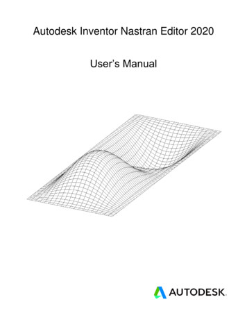
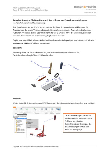
Constructive Solid Geometry Concepts3-3IntroductionIn the 1980s, one of the main advancements in solid modeling was the development ofthe Constructive Solid Geometry (CSG) method. CSG describes the solid model ascombinations of basic three-dimensional shapes (primitive solids). The basic primitivesolid set typically includes Rectangular-prism (Block), Cylinder, Cone, Sphere, andTorus (Tube). Two solid objects can be combined into one object in various ways usingoperations known as Boolean operations. There are three basic Boolean operations:JOIN (Union), CUT (Difference), and INTERSECT. The JOIN operation combinesthe two volumes included in the different solids into a single solid. The CUT operationsubtracts the volume of one solid object from the other solid object. The INTERSECToperation keeps only the volume common to both solid objects. The CSG method is alsoknown as the Machinist's Approach, as the method is parallel to machine shoppractices.Primitive SolidsJOINCUTINTERSECTCUT
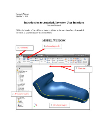
3-4Autodesk Inventor and Engineering GraphicsBinary TreeThe CSG is also referred to as the method used to store a solid model in the database. Theresulting solid can be easily represented by what is called a binary tree. In a binary tree,the terminal branches (leaves) are the various primitives that are linked together to makethe final solid object (the root). The binary tree is an effective way to keep track of thehistory of the resulting solid. By keeping track of the history, the solid model can be rebuilt by re-linking through the binary tree. This provides a convenient way to modify themodel. We can make modifications at the appropriate links in the binary tree and re-linkthe rest of the history tree without building a new model.Terminal branchesLeaf 1Leaf 2ResultROOTUnion
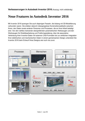
Constructive Solid Geometry Concepts3-5The Locator DesignThe CSG concept is one of the important building blocks for feature-based modeling. InAutodesk Inventor, the CSG concept can be used as a planning tool to determine thenumber of features that are needed to construct the model. It is also a good practice tocreate features that are parallel to the manufacturing process required for the design. Withparametric modeling, we are no longer limited to using only the predefined basic solidshapes. In fact, any solid features we create in Autodesk Inventor are used as primitivesolids; parametric modeling allows us to maintain full control of the design variables thatare used to describe the features. In this lesson, a more in-depth look at the parametricmodeling procedure is presented. The equivalent CSG operation for each feature is alsoillustrated. Before going through the tutorial, on your own make a sketch of a CSG binary tree ofthe Locator design using only two basic types of primitive solids: cylinder andrectangular prism. In your sketch, how many Boolean operations will be required tocreate the model? What is your choice of the first primitive solid to use, and why?Take a few minutes to consider these questions and do the preliminary planning bysketching on a piece of paper. Compare the sketch you make to the CSG binary treesteps shown on the next page. Note that there are many different possibilities incombining the basic primitive solids to form the solid model. Even for the simplestdesign, it is possible to take several different approaches to creating the same solidmodel.
3-6Autodesk Inventor and Engineering GraphicsModeling Strategy – CSG Binary TreeUNIONCUCUTCUT
Constructive Solid Geometry Concepts3-7Starting Autodesk Inventor1. Select the Autodesk Inventor option on the Start menu or select the AutodeskInventor icon on the desktop to start Autodesk Inventor. The Autodesk Inventormain window will appear on the screen.2. Select the New File icon with a single click of theleft-mouse-button in the Launch toolbar. Every object we construct in a CAD system is measured in units. We shoulddetermine the value of the units within the CAD system before creating the firstgeometric entities. For example, in one model, a unit might equal one millimeter ofthe real-world object; in another model, a unit might equal an inch. In AutodeskInventor, the Choose Template option is used to control how Autodesk Inventorinterprets the coordinate and angle entries.3. Select the Metric tab as shown below. We will use themillimeter (mm) setting for this example.4. In the New File – Part Templatearea, select the Standard(mm).ipticon as shown.5. Confirm the Parametric-Modelingproject is activated; note theProjects button is available toview/modify the active project.6. Pick Create in the Startup dialog box to accept the selected settings.
3-8Autodesk Inventor and Engineering GraphicsBase FeatureIn parametric modeling, the first solid feature is called the base feature, which usually isthe primary shape of the model. Depending upon the design intent, additional features areadded to the base feature.Some of the considerations involved in selecting the base feature are: Design intent – Determine the functionality of the design; identify the feature that iscentral to the design. Order of features – Choose the feature that is the logical base in terms of the orderof features in the design. Ease of making modifications – Select a base feature that is more stable and is lesslikely to be changed.1. Activate the Start 2D Sketch icon with asingle click of the left-mouse-button.2. Move the cursor over the edge of the XZ Plane in the graphics area. When the XZPlane is highlighted, click once with the left-mouse-button to select the Plane as thesketch plane for the new sketch.
Constructive Solid Geometry Concepts3-9GRID Display Setup1. In the Ribbon toolbar panel, select[Tools] [Document Settings].2. In the Document Settings dialog box, click on the Sketch tab as shown in the belowfigure.3. Set the X and Y Snap Spacing to 5 mm.3. Set to 5 mm4. Set to 54. Change Grid Display to display one major line every 5 minor lines.5. Pick OK to exit theSketch Settings dialogbox. Note that although theSnap to grid option isalso available, its usage inparametric modeling isnot recommended. On your own, use the dynamic Zoom function to view the grid setup. Refer to Page2-26 on how to switch on the grid lines display options if necessary.
3-10Autodesk Inventor and Engineering Graphics A rectangular block will be first created as the base feature of the Locator design.6. Click on the rotate-left arrow on the view cube to rotate thedisplay.7. Switch back to the Sketch tab andselect the Two point rectanglecommand by clicking once with theleft-mouse-button.8. Create a rectangle of arbitrary size by selecting two locations on the screen as shownbelow.Second CornerFirst Corner9. Inside the graphics window, click once with theright-mouse-button to bring up the optionmenu.10. Select OK to end the Rectangle command.11. Activate the General Dimensioncommand by clicking once with the leftmouse-button. The General Dimensioncommand allows us to quickly create andmodify dimensions.
Constructive Solid Geometry Concepts3-1112. Inside the graphics window, click once with the rightmouse-button to bring up the option menu and clickEdit Dimension to turn OFF the editing option whilecreating dimensions.13. The message “Select Geometry to Dimension” is displayed in the Status Bar area atthe bottom of the Autodesk Inventor window. Select the bottom horizontal line byleft-clicking once on the line.13. Select the bottomhorizontal line as thegeometry to dimension.14. Pick a locationbelow the line to placethe dimension.14. Move the graphics cursor below the selected line and left-click to place thedimension. (Note that the value displayed on your screen might be different than whatis shown in the above figure.)15. On your own, create a vertical size dimension of the sketched rectangle as shown.16. Inside the graphics window, click once with the rightmouse-button to bring up the option menu and clickOK to end the Dimension command.
3-12Autodesk Inventor and Engineering GraphicsModel Dimensions Format1. In the Ribbon tabs, select[Tools] [Document Settings].2. In the Document Settings dialog box, set the Modeling Dimension Display toDisplay as value as shown in the figure.3. Also set the precisionto no digits after thedecimal point for boththe linear dimensionand angular dimensiondisplays as shown inthe above figure.4. Pick OK to exit the Document Settings dialog box.Modifying the Dimensions of the Sketch1. Select the height dimension that is to theright side of the sketch by double-clickingwith the left-mouse-button on the dimensiontext.
Constructive Solid Geometry Concepts3-132. In the Edit Dimension window, the currentlength of the line is displayed. Enter 50 to setthe selected length of the sketch to 50millimeters.3. Click on the Accept icon to accept the enteredvalue. Autodesk Inventor will now update the profile with the new dimension value.4. On your own, repeat the above steps and adjust the dimensions so that the sketchappears as shown below. Also exit the Dimension command.Repositioning Dimensions1. Move the cursor near the vertical dimension; notethat the dimension is highlighted. Move the cursorslowly until a small arrows marker appears next tothe cursor, as shown in the figure.2. Drag with the left-mouse-button to reposition theselected dimension.3. Repeat the above steps to reposition the horizontaldimension.
3-14Autodesk Inventor and Engineering GraphicsUsing the Measure ToolsAutodesk Inventor also provides several measuring tools that allow us to measure area,perimeter and additional information of the constructed 2D sketches.1. In the Inspect Ribbon tab, left-click once on theMeasure option as shown. Note that other measurement options are alsoavailable in the toolbar.2. Click on the top edge of the rectangle asshown.3. The associated length measurement of theselected geometry is displayed in theLength dialog box as shown.4. Inside the graphics window, right-click once to bring upthe Option menu and select Restart as shown.5. Move the cursor on top of any of the edgesand click once with the right-mouse-buttonto bring up the Option menu and chooseSelect Other. as shown.
Constructive Solid Geometry Concepts3-156. In the Selection list, left-click once to pick theCurve Loop option as shown. The perimeter of the rectangle is displayed asshown.7. Click on the [X] icon to end theMeasure command as shown.8. In the Inspect Ribbon tab, left-click once on the Region Properties option asshown.
3-16Autodesk Inventor and Engineering Graphics9. Click on the inside of the rectangle; noticethe region is highlighted as the cursor ismoved inside the rectangle, as shown.10. In the Region Properties dialog box, click on theCalculate button to perform the calculations of theassociated geometry information. In the Region Properties dialog box,the detailed region properties arecalculated and displayed, includingthe Area Moments of Inertia, Area andPerimeter.11. Click Done to exit the RegionProperties command.12. Select Finish Sketch in the Ribbon to end theSketch option.
Constructive Solid Geometry Concepts3-17Completing the Base Solid Feature1. In the 3D Model tab select the Extrudecommand by clicking the left-mouse-buttonon the icon.2. In the Extrude pop-up window, enter 15 asthe extrusion distance. Notice that the sketchregion is automatically selected as theextrusion profile.3. Click on the OK button to proceed with creating the 3D part. Use the DynamicViewing options to view the created part. Press F6 to change the display to theisometric view
Autodesk Inventor, the CSG concept can be used as a planning tool to determine the number of features that are needed to construct the model. It is also a good practice to create features that are parallel to the manufacturing process required for the design. With parametric modeling, we are no longer limited to using only the predefined basic solid shapes. In fact, any solid features we .