Transcription
Engineering DesignGraphics withAutodesk Inventor 2020
This page intentionally left blank
Engineering DesignGraphics withAutodesk Inventor 2020James D. Bethune
Engineering Design Graphics with Autodesk Inventor 2020Copyright 2020 by Pearson Education, Inc. All rights reserved. This publication isprotected by Copyright and permission should be obtained from the publisher prior to anyprohibited reproduction, storage in a retrieval system, or transmission in any form or by anymeans, electronic, mechanical, photocopying, recording, or likewise. For information regarding permissions, request forms and the appropriate contacts within the Pearson EducationGlobal Rights & Permissions Department, please visit www.pearsoned.com/permissions/.Many of the designations by manufacturers and sellers to distinguish their products areclaimed as trademarks. Where those designations appear in this book, and the publisher wasaware of a trademark claim, the designations have been printed in initial caps or all caps.Credits and acknowledgments borrowed from other sources and reproduced, with permission,in this textbook appear on the appropriate page within the text. Unless otherwise stated, allartwork has been provided by the author.Autodesk screen shots reprinted courtesy of Autodesk, Inc. 2019. All rights reserved.Autodesk, AutoCAD, Autodesk Inventor, and Inventor are registered trademarks or trademarks of Autodesk, Inc., in the U.S.A. and certain other countries.Notice of Liability:The publication is designed to provide tutorial information about Inventor and/or otherAutodesk computer programs. Every effort has been made to make this publication completeand as accurate as possible. The reader is expressly cautioned to use any and all precautionsnecessary, and to take appropriate steps to avoid hazards, when engaging in the activitiesdescribed herein.Neither the author nor the publisher makes any representations or warranties of any kind,with respect to the materials set forth in this publication, express or implied, including without limitation any warranties of fitness for a particular purpose or merchantability. Nor shallthe author or the publisher be liable for any special, consequential, or exemplary damagesresulting, in whole or in part, directly or indirectly, from the reader’s use of, or reliance upon,this material or subsequent revisions of this material.Acquisitions Editor: Chhavi VigManaging Editor: Sandra SchroederSenior Production Editor: Lori LyonsCover Designer: Chuti PrasertsithLibrary of Congress Control Number is on fileISBN 10: 0-13-556309-0ISBN 13: ce Project Management:Gayathri Umashankaran/codeMantraComposition: codeMantraProofreader: Abigail Manheim
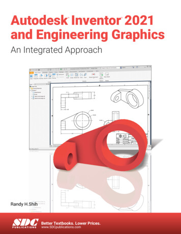
PrefaceThis book introduces Autodesk Inventor 2020 and shows how to useAutodesk Inventor to create and document drawings and designs. Thebook puts heavy emphasis on engineering drawings and on drawing components used in engineering drawings such as springs, bearings, cams,and gears. It shows how to create drawings using many different formatssuch as .ipt, .iam, ipn, and .idw for both English and metric units. Itexplains how to create drawings using the tools located under the Designtab and how to extract parts from the Content Center.All topics are presented using a step-by-step format so that thereader can work directly from the text to the screen. There are manyeasy-to-understand labeled illustrations. The book contains many sampleproblems that demonstrate the subjects being discussed. Each chaptercontains a variety of projects that serve to reinforce the material just presented and allow the reader to practice the techniques described.Chapters 1 and 2 present 2D sketching tools and the Extrude tool.These chapters serve as an introduction to the program. There are 38Chapter Projects to help students apply the material presented.Chapter 3 demonstrates the tools needed to create 3D models, including Shell, Hole, Rib, Split, Loft, Sweep, and Coil. Work points, workaxes, and work planes are explained and demonstrated.Chapter 4 shows how to create orthographic views from 3D models.The creation of isometric views, section views, and auxiliary views is covered. In addition, a comparison between first- and third-angle projection ispresented using both ANSI and ISO conventions.Chapter 5 shows how to create assembly drawings using both thebottom-up and the top-down processes. The chapter includes presentationdrawings and exploded isometric drawings with title blocks, parts lists,revision blocks, and tolerance blocks. There is an extensive step-by-stepexample that shows how to create an animated assembly—that is, a drawing that moves on the screen.Chapter 6 covers threads and fasteners. Drawing conventions andcallouts are defined for both inch and metric threads. The chapter showshow to calculate thread lengths and how to choose the appropriate fastener from Inventor’s Content Center. The Content Center also includesan extensive listing of nuts, setscrews, washers, and rivets.Chapter 7 shows how to apply dimensions to drawings. Both ANSIand ISO standards are demonstrated, but the emphasis is on ANSI standards. Different styles of dimensioning, including ordinate and baseline, andusing Inventor’s Hole Table are presented. Applying dimensions to a drawing is considered an important skill, so many examples and sample problems are included.Chapter 8 is an extensive discussion of tolerancing, including geometrictolerances. The chapter first shows how to use Inventor to apply tolerancesto a drawing. The chapter then shows how to calculate tolerances in variousdesign situations. Positional tolerances for both linear and geometric applications are included. The chapter introduces the Limits/Fits Calculatorlocated on the Power Transmission panel under the Design tab.Chapter 9 shows how to draw springs using the Standard.ipt formatand the Coil tool. It also shows how to draw springs using the tools on thev
Spring panel under the Design tab. Compression, extension, torsion, andBelleville springs are included.Chapter 10 shows how to draw shafts using the Shaft tool underthe Design tab. Chamfers, retaining rings, retaining ring grooves, keysand keyways, splines, pins, O-rings, and O-ring grooves are covered. Thechapter contains many exercise problems.Chapter 11 shows how to match bearings to specific shafts using theContent Center. Plain, ball, and thrust bearings are presented. An explanation of tolerances between a shaft and bearing bore and between thebearing’s outside diameter and the assembly housing is given. Both ANSIand ISO standards are presented.Chapter 12 emphasizes how to draw gears and how to mount theminto assembly drawings. Spur, bevel, and worm gears are introduced. Thechapter shows how to create gear hubs with setscrews, and keyways withkeys, and how to draw assembly drawings that include gears. There aretwo new extensive assembly exercise problems.Chapter 13 shows how to draw basic sheet metal parts, including features such as tabs, reliefs, flanges, cuts, holes, and hole patterns.Chapter 14 shows how to create and draw weldments. Only fillet andgroove welds are covered.Chapter 15 shows how to design and draw cams. Displacement diagrams and different types of followers are discussed.Chapter 16 is available online and includes two large project-typeproblems. They can be used as team projects to help students learn towork together to share and compile files, or they can be used as end-ofthe-semester individual projects. This chapter can be found on the web asa supplement to the Instructor’s Manual at http://pearsonhighered.com/irc. Instructors may distribute to students.AcknowledgmentsI would like to thank the following reviewers for their invaluable input:Rebecca Rosenbauer, Lafayette College; Antigone Sharris, Triton College;Nancy E. Study, Virginia State University; and Marsha Walton, FingerLakes Community College.Thanks to my family: David, Maria, Randy, Sandra, Hannah, Wil,Madison, Jack, Luke, Sam, and Ben.A special thanks to Cheryl.James D. BethuneviPreface
Style Conventions in Engineering Design Graphics withAutodesk Inventor 2020Text ElementExampleKey terms—Bold and italic on first mention in thebody of the text. Brief glossary definition in marginfollowing first mention.Create a work axis by clicking on the edgeof the block.Inventor tools—Bold and follow Inventor capitalization convention.Click on the Line tool.Toolbar names, menu items, and dialog boxnames—Bold and follow capitalization conventionin Inventor tab, panel, or pull-down menu (generallyfirst letter capitalized).The Design tabDialog box controls/buttons/input items—Boldand follow capitalization convention of the name ofthe item or the name shown in the Inventor tooltip.Choose the Metric tab in the New Filedialog box.The Modify panelThe 2D Chamfer dialog boxThe File pull-down menuClick on the Flush button on the PlaceConstraint dialog box.On the Assembly tab, set the Offset to0.000 mm.ONG 300/320 sat 76vii
This page intentionally left blank
Brief ContentsCHAPTER 1Get StartedCHAPTER 2Two-Dimensional Sketching27CHAPTER 33D Models85CHAPTER 4Orthographic Views167CHAPTER 5Assembly Drawings221CHAPTER 6Threads and Fasteners311CHAPTER 7Dimensioning a Drawing389CHAPTER 8Tolerancing455CHAPTER 9Springs5631CHAPTER 10 Shafts605CHAPTER 11 Bearings671CHAPTER 12 Gears697CHAPTER 13 Sheet Metal Drawings747CHAPTER 14 Weldment Drawings779CHAPTER 15 Cams799Index823ix
This page intentionally left blank
ContentsCHAPTER 1 Get StartedChapter ObjectivesIntroductionCreating a First SketchThe Undo ToolCreating a Solid ModelSample Problem SP1-1Sample Problem SP1-2 Angular ShapesChapter SummaryChapter Test QuestionsChapter Project1114991219222224CHAPTER 2 Two-Dimensional Sketching 27Chapter ObjectivesIntroductionThe Sketch mferPolygonTextGeometry endOffsetEditing a SketchSample Problem 566676870Chapter SummaryChapter Test QuestionsChapter Project757577CHAPTER 3 3D Models85Chapter volveHolesFilletFull Round FilletFace FilletCreating a Variable FilletChamferFace DraftShellSplitMirrorRectangular PatternCircular PatternSketch PlanesEditing a 3D ModelDefault Planes and AxesWork PlanesSample Problem SP3-1Angled Work PlanesOffset Work PlanesWork PointsRibs (WEBs)LoftSweepCoilModel MaterialChapter SummaryChapter Test QuestionsChapter ER 4 Orthographic Views167Chapter ObjectivesIntroductionFundamentals of Orthographic ViewsOrthographic Views with InventorIsometric ViewsSection ViewsOffset Section ViewsAligned Section ViewsDetail ViewsBreak ViewsAuxiliary ViewsASME ter SummaryChapter Test QuestionsChapter Project194194198xi
CHAPTER 5 Assembly Drawings221CHAPTER 7 Dimensioning a Drawing389Chapter ObjectivesIntroductionBottom-Up and Top-Down AssembliesStarting an Assembly DrawingDegrees of FreedomFree Move and Free Rotate ToolsConstrainPresentation DrawingsAnimationIsometric DrawingsAssembly NumbersParts ListTitle BlockSubassembliesDrawing SheetsOther Types of Drawing BlocksTop-Down AssembliesEditing a Part within an Assembly DrawingPatterning ComponentsMirroring ComponentsCopying 49253255260280284285286Chapter ObjectivesIntroductionTerminology and Conventions—ANSICreating Drawing DimensionsDrawing ScaleUnitsAligned DimensionsRadius and Diameter DimensionsDimensioning HolesSample Problem SP7-1Dimensioning Counterbored,Countersunk HolesAngular DimensionsOrdinate DimensionsBaseline DimensionsHole TablesLocating DimensionsFillets and RoundsRounded Shapes—InternalRounded Shapes—ExternalIrregular SurfacesPolar DimensionsChamfersKnurlingKeys and KeyseatsSymbols and AbbreviationsSymmetrical and Centerline SymbolsDimensioning to a PointDimensioning Section ViewsDimensioning Orthographic Views3D DimensionsSample Problem SP7-2Sample Problem SP7-3389389390392399400403404406407Chapter SummaryChapter Test QuestionsChapter ProjectCHAPTER 6 Threads and Fasteners311Chapter ObjectivesIntroductionThread TerminologyThread Callouts—Metric UnitsThread Callouts—ANSI Unified Screw ThreadsThread RepresentationsInternal ThreadsThreaded Blind HolesCreating Threaded Holes Using the Hole ToolStandard FastenersSizing a Threaded Hole to Accept a ScrewScrews and NutsTypes of Threaded FastenersFlat Head Screws—Countersunk HolesCounterboresDrawing Fasteners Not Includedin the Content CenterSample Problem SP6-1WashersSetscrewsRivetsSample Problem Chapter SummaryChapter Test QuestionsChapter 4367Chapter SummaryChapter Test QuestionsChapter 427427428429429430431433436436439CHAPTER 8 Tolerancing455Chapter ObjectivesIntroductionDirect Tolerance MethodsTolerance ExpressionsUnderstanding Plus and Minus TolerancesCreating Plus and Minus TolerancesLimit TolerancesAngular TolerancesStandard TolerancesDouble DimensioningChain Dimensions and BaselineDimensionsTolerance Studies455455455457457458462463465466467469
Rectangular DimensionsHole LocationsChoosing a Shaft for a Toleranced HoleSample Problem SP8-1Sample Problem SP8-2Nominal SizesStandard Fits (Metric Values)Hole and Shaft BasisVisual Presentations of the Holeand Shaft TolerancesStandard Fits (Inch Values)Preferred and Standard SizesSurface FinishesSurface Control SymbolsGeometric TolerancesTolerances of FormStraightnessStraightness (RFS and MMC)CircularityCylindricityGeometric TolerancesUsing InventorTolerances of OrientationDatumsPerpen
Autodesk Inventor to create and document drawings and designs. The book puts heavy emphasis on engineering drawings and on drawing com- ponents used in engineering drawings such as springs, bearings, cams, and gears. It shows how to create drawings using many different formats such as .ipt, .iam, ipn, and .idw for both English and metric units. It explains how to create drawings using the .
