Transcription
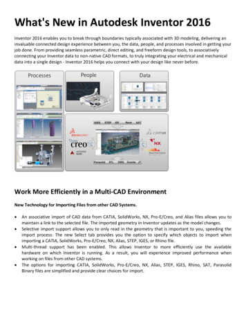
What's New in Autodesk Inventor 2016Inventor 2016 enables you to break through boundaries typically associated with 3D modeling, delivering aninvaluable connected design experience between you, the data, people, and processes involved in getting yourjob done. From providing seamless parametric, direct editing, and freeform design tools, to associativelyconnecting your Inventor data to non-native CAD formats, to truly integrating your electrical and mechanicaldata into a single design - Inventor 2016 helps you connect with your design like never before.Work More Efficiently in a Multi-CAD EnvironmentNew Technology for Importing Files from other CAD Systems. An associative import of CAD data from CATIA, SolidWorks, NX, Pro-E/Creo, and Alias files allows you tomaintain a link to the selected file. The imported geometry in Inventor updates as the model changes.Selective import support allows you to only read in the geometry that is important to you, speeding theimport process: The new Select tab provides you the option to specify which objects to import whenimporting a CATIA, SolidWorks, Pro-E/Creo, NX, Alias, STEP, IGES, or Rhino file.Multi-thread support has been enabled. This allows Inventor to more efficiently use the availablehardware on which Inventor is running. As a result, you will experience improved performance whenworking on files from other CAD systems.The options for importing CATIA, SolidWorks, Pro-E/Creo, NX, Alias, STEP, IGES, Rhino, SAT, ParasolidBinary files are simplified and provide clear choices for import.
Associative DWG Quickly insert an AutoCAD DWG file in an Inventor part file as a DWG underlay using the Import commandin the 3D Model tab, Create panel.You can add assembly relationships to underlay geometry.Use the Project DWG Geometry command to project DWG geometry, polylines, open or closed loops, andDWG blocks. Then you can use the projected sketch elements to create modeling features.Your 3D Inventor models based on the DWG geometry update when the 2D geometry changes inAutoCAD.AutoCAD Electrical and Inventor Interoperability The new Electromechanical link between Inventor and AutoCAD Electrical provides a smooth dataexchange between your 2D and 3D electrical designs.When you create a link between an AutoCAD Electrical and an Inventor assembly (not available in InventorLT), the project files become associative: Design data changes made in one product are updated in theother via Sync.The Location View command on the new Electromechanical tab on the Assembly (not available in InventorLT) ribbon in Inventor displays the devices and wiring contained in both the AutoCAD Electrical Drawingsand Inventor Assemblies.Shape CreationUse powerful new commands and workflows in the Freeform modeling environment. Some of the highlightsare: Work with open surfaces or closed shapes. Convert existing model faces to freeform geometry for shape refinement. The new Freeform Thicken command creates solids, offset surfaces, or shell walls. Unweld edges to split and move a freeform body segment. Delete faces.
3D Printing EnvironmentA new environment is added that lets you position and orient your design within the print space of theselected 3D printer. You can also update the part in the print environment that does not impact the sourcedocument. When you are finished, you can send the results to Print Studio or other printing software to beginprinting the part.
Drawing Environment Drawing view creation is simplified, and uses in-canvas tools.Text formatting is expanded with new options: Bullets and numbering, strike-through text, enhancedformatting (all caps, title case, lower case).Surface texture and feature control frame symbols are updated to the latest standards.Many new graphical symbols are available, and can be inserted in various types of drawing annotations.Balloon styles can use custom balloon shapes.A new Single Segment Leader option allows you to create drawing annotations with a single leadersegment.You can align drawing annotations vertically, horizontally, or to an edge.Create a view sketch on a model with included work features and select those work features with theProject Geometry command.Quickly access and share your collection of sketch symbols through a new external Sketch Symbols Library.This library is an Inventor drawing file that, by default, is located in a subfolder of the Design Data locationof your project. This new feature offers the following new functions:o A search and filter feature in the Sketch Symbols Library dialog box.o Preview the sketch in a preview pane within the dialog box before placing the sketch.o Browser expansion state remains throughout session when placing sketch symbols.o A Sketch Symbol Library can be created in IDW and DWG formats, allowing insertion of symbolscontained within the library file from either format.o Save your sketch symbols to a customized library.Improved Start Up and Learning ExperienceThe new start-up and learning experience combine to make learning and using Inventor faster and easier. Movable and resizable Inventor Home panels. Home provides greater access to common file tasks. Files can be removed from the recent documents list. Vault status is displayed in the recent documents list. Create custom shortcuts to provide fast access to frequently used files and locations. Help content was edited to provide better search results. Topic content was combined to reduce the number of clicks.
Graphics/Visualization/Studio EnhancementsSome highlights are: ALL lighting styles in Inventor Studio are now associated with an IBL. A lighting style can have zero locallights but must have one IBL.IBL (Image Based Lighting) based lighting styles provides better lighting sources in Inventor Studio withenriched IBL collection.When you enter the Studio Environment, all legacy local lights are now disabled by default. It isrecommended you use IBL for better rendering results. You can turn on specific local lights manually whennecessary.All newly created lighting styles are associated with the default IBL automatically. You can change theassociated IBL to another IBL as desired.The enhanced visual effect for shaded visual style makes it more consistent with the realistic visual style.The rendering engine in Inventor Studio was changed to RapidRT with advanced configurations for betterquality rendering.The Studio Render Illustration settings have been moved to the View tab Appearance Panel Visual Stylesdrop-down menu. The new and enhanced Technical Illustration command creates a realistic illustrationeffect in the graphics window.
Workflow EnhancementsAmong the many enhancements, are:General Use Escape (Esc) key to cancel an operation in select processes. Multiple productivity enhancements made to dialog boxes. Add all window tile styles to the task bar. Dock an Inventor browser on any application's window edge. Hide all sketch dimensions now available in the Object Visibility menu. Import/Export external rules configuration for iLogic (not available in Inventor LT).Sheet metal parts Multi-body support is added to sheet metal. Support for zero bend radius is added to many commands.Material thickness is detected when you convert a part to a sheet metal part.Punch tool shows a count of the center selections.Part appearance and body, feature, or face color overrides can be pushed from derived part to new partA new Use color override from source component option has been added to the Derived Assembly (notavailable in Inventor LT), Derived Part, Make Part, and Make Component dialog boxes. Selecting this optionpushes the Part appearance and body, feature, or face color overrides to be pushed from the derived part tothe new part.Tube and Pipe setting enhancements (not available in Inventor LT)You can now customize file names for fittings and populate part numbers into your parts list within thedrawing environment. Previously, you could only change the name of your conduit items, but now you canupdate fittings as well.
Parts Face draft contains powerful new options that let you Fix or Move the parting line. Ruled Surface is added to the surfacing commands. The Mirror and Pattern commands support multiple solid body selection. Previously, nonlinear patterns of a solid body in a multi body part file have not been possible. You can nowcreate nonlinear patterns for solid bodies. Drag a sketch above the parent feature in the browser to share it. The Measure command now allows you to measure an angle to the midpoint of any segment. This optionis achieved by hovering your mouse over the midpoint of a segment until a yellow dot appears.Sketch Identify which workplane or face a sketch was created on. The selected Show All or Hide All Constraints display setting remains active as you sketch and throughoutyour editing session. You can now create tangent dimensions between circular or arc geometry within a 2D sketch. The Initial View Scale property of the first drawing review placed on the sheet is added in the SheetProperties group within the Format Text dialog box. The Sketch Dimensions option is added to the Object Visibility list. Select this option to display 2D or 3Dsketches and hide all related sketch dimensions. Sharing a sketch is made visible by dragging above the feature in browser. New snap points added to the context menu: Endpoint, Apparent Intersection, Quadrant, and Mid of 2points. You can now modify Start Sketch and select a view or sheet before sketching.Assembly (not available in Inventor LT) New safety factor calculation warning displays in Stress Analysis. The Midplane option has been added to the assembly Pattern command. Select the Midplane option tocreate a pattern distributed on both sides of the original component. Replace All feature available for highlighted components within an assembly. Select multiple sick constraints within Design Doctor to delete.Drawings You can start a drawing from any open model, and automatically apply the current model camera andrepresentations in the base view. In-canvas tools in the Base View command simplify creation of a base view and projected views.For example, you can use the ViewCube to orient the model, set the view scale by dragging a view corner,or adjust projected views while creating the base view.Presentations (not available in Inventor LT) Tweak command is redesigned to use direct manipulation tools. Creating and editing of trails is easier. Component selection is simplified. Auto Explode command is added to the ribbon and improved.Keep reading for details on all of these great enhancements and more.
GeneralVisualization, Graphics, and Studio EnhancementsStudio EnhancementsNew support for Image Based Lighting (IBL)All lighting styles in Inventor Studio are now associated with an IBL. IBL provides a better lighting source.Image-based lighting from the modeling environment is now supported by Inventor Studio. To render fromthe modeling lighting environment, use the commands available on the View tab, then use the CurrentLighting in the Studio Render Image dialog box, or change to other lighting styles from Render Image dialogbox.
New 2016 IBL Lighting Style features IBL provides associationBackground turn on/offSupport additive lightsAdvanced rendering engine RapidRT provides new configurations for rendering Time duration/iterations/unlimited modeLighting and Material Accuracy modes
Obsolete options removed: Scene Style: The Ground plane and shadow effect settings specified in the View tab now display in therendered model in Inventor Studio. The Studio Render Illustration settings have been moved to the View tab Appearance Panel Visual Stylesdrop-down menu. The new Technical Illustration command creates a realistic illustration effect in thegraphics window.Ground Plane and Shadow Effect display in final rendering resultThe Ground plane and shadow effect settings specified in the View tab will now display in the rendered model.
Graphics EnhancementsThe enhanced Shaded visual style display effect is now more consistent with Realistic visual style. Enhancedvisual effect for shaded view. The following two images compare the results of using Shaded View in 2015 and2016. High rendering performance is maintained.Technical Illustration Visual StyleThe Studio Render Illustration settings have been moved to the View tab Appearance Panel Visual Stylesdrop-down menu. The new Technical Illustration command creates a realistic illustration effect in the graphicswindow.New IBL styles11 new lighting styles are added to the View tab Appearance Panel Lighting Styles menu. These includeDark Sky, Gray Room, Infinity Pool, Photo Booth, Tranquility Blue, Sharp Highlights, Rim Highlights, Cool Light,Warm Light, Soft Light, and Grid Light.Changes to Ray Tracing The Ray Tracing modes are changed to Low, Draft, and High to indicate the lighting and material accuracy.The progress status bar is changed to display quality measurement instead of percentage progress.You can now save an image any time during Ray Tracing.
Visual enhancement in drawingsThe new Reflection Environment settings in the drawing Document Settings dialog box allow you to applyspecular effect and specify a Reflection map in a Drawing (.idw) file.
Text and Leader TextRedesigned Format Text Dialog BoxThe Format Text dialog box is simplified and refined to be clear and easy to use. Size of the dialog box isreduced to provide more space for editing in the graphic window.Bullets and Numbering in TextYou can create bulleted or numbered lists in the Format Text dialog box. One bulleting style and severalnumbering styles are available.Text Case OptionsIn the Format Text dialog box, select a string, and select a Text Case option to convert the string toUPPERCASE, lowercase, or Title Case.Strikethrough TextIn the Format Text dialog box, click the Strikethrough bu
Inventor 2016 enables you to break through boundaries typically associated with 3D modeling, delivering an invaluable connected design experience between you, the data, people, and processes involved in getting your job done. From providing seamless parametric, direct editing, and freeform design tools, to associatively connecting your Inventor data to non-native CAD formats, to truly .