Transcription
Learning Autodesk Inventor 2016 Modeling, Assembly and AnalysisRandy H. ShihSDCP U B L I C AT I O N SBetter Textbooks. Lower Prices.www.SDCpublications.com
Visit the following websites to learn more about this book:Powered by TCPDF (www.tcpdf.org)
2-1Chapter 2Parametric Modeling Fundamentals Create Simple Extruded Solid Models Understand the Basic ParametricModeling Procedure Create 2-D Sketches Understand the “Shape before Size”Design Approach Use the Dynamic Viewing Commands Create and Edit Parametric Dimensions
2-2Learning Autodesk InventorIntroductionThe feature-based parametric modeling technique enables the designer to incorporatethe original design intent into the construction of the model. The word parametric meansthe geometric definitions of the design, such as dimensions, can be varied at any time inthe design process. Parametric modeling is accomplished by identifying and creating thekey features of the design with the aid of computer software. The design variables,described in the sketches as parametric relations, can then be used to quicklymodify/update the design.In Autodesk Inventor, the parametric part modeling process involves the following steps:1. Create a rough two-dimensional sketch of the basic shape of the base featureof the design.2. Apply/modify constraints and dimensions to the two-dimensional sketch.3. Extrude, revolve, or sweep the parametric two-dimensional sketch to createthe base solid feature of the design.4. Add additional parametric features by identifying feature relations andcomplete the design.5. Perform analyses on the computer model and refine the design as needed.6. Create the desired drawing views to document the design.The approach of creating two-dimensional sketches of the three-dimensional features isan effective way to construct solid models. Many designs are in fact the same shape inone direction. Computer input and output devices we use today are largely twodimensional in nature, which makes this modeling technique quite practical. This methodalso conforms to the design process that helps the designer with conceptual design alongwith the capability to capture the design intent. Most engineers and designers can relateto the experience of making rough sketches on restaurant napkins to convey conceptualdesign ideas. Autodesk Inventor provides many powerful modeling and design-tools, andthere are many different approaches to accomplishing modeling tasks. The basic principleof feature-based modeling is to build models by adding simple features one at a time. Inthis chapter, the general parametric part modeling procedure is illustrated; a very simplesolid model with extruded features is used to introduce the Autodesk Inventor userinterface. The display viewing functions and the basic two-dimensional sketching toolsare also demonstrated.
Parametric Modeling FundamentalsThe Tiger Head DesignStarting Autodesk Inventor1. Select the Autodesk Inventor option on the Start menu or select theAutodesk Inventor icon on the desktop to start Autodesk Inventor. TheAutodesk Inventor main window will appear on the screen.2. Select the Projects icon with a single click of theleft-mouse-button.2-3
2-4Learning Autodesk Inventor3. In the Projects list, double-click on the Parametric-Modeling project name toactivate the project as shown. Note that Autodesk Inventor will keep this activated project as the default projectuntil another project is activated.4. Click Done to accept the setting and end the Projects Editor.5. Select the New File icon with a single click of theleft-mouse-button. Notice the Parametric-Modeling project name isdisplayed as the active project.6. Select the English tab as shown below. When starting a new CAD file, the firstthing we should do is choose the units we would like to use. We will use theEnglish setting (inches) for this example.6. English7. Standard.ipt7. Select the Standard(in).ipt icon as shown.8. Pick Create in the New File dialog box to accept the selected settings.
Parametric Modeling Fundamentals2-5The Default Autodesk Inventor Screen LayoutThe default Autodesk Inventor drawing screen contains the pull-down menus, theStandard toolbar, the Features toolbar, the Sketch toolbar, the drawing area, the browserarea, and the Status Bar. A line of quick text appears next to the icon as you move themouse cursor over different icons. You may resize the Autodesk Inventor drawingwindow by clicking and dragging the edges of the window, or relocate the window byclicking dragging the window title area.Application MenuQuick Access ToolbarThe RibbonCreate Toolbar PanelGraphicsWindowModelBrowser3D IndicatorMessage or Single-line Help The Ribbon is a new feature in Autodesk Inventor since the 2011 release. TheRibbon is composed of a series of tool panels, which are organized into tabslabeled by task. The Ribbon provides a compact palette of all of the toolsnecessary to accomplish the different modeling tasks. The drop-down arrow nextto any icon indicates additional commands are available on the expanded panel;access the expanded panel by clicking on the drop-down arrow.
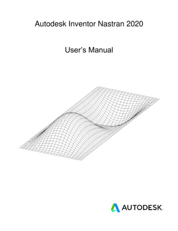
2-6Learning Autodesk InventorSketch Plane – It is an XY Monitor, but an XYZ WorldDesign modeling software is becoming morepowerful and user friendly, yet the system stilldoes only what the user tells it to do. Whenusing a geometric modeler, we therefore needto have a good understanding of what itsinherent limitations are.In most 3D geometric modelers, 3D objectsare located and defined in what is usuallycalled world space or global space. Althougha number of different coordinate systems canbe used to create and manipulate objects in a3D modeling system, the objects are typicallydefined and stored using the world space. Theworld space is usually a 3D Cartesiancoordinate system that the user cannot changeor manipulate.In engineering designs, models can be very complex, and it would be tedious andconfusing if only the world coordinate system were available. Practical 3D modelingsystems allow the user to define Local Coordinate Systems (LCS) or User CoordinateSystems (UCS) relative to the world coordinate system. Once a local coordinate systemis defined, we can then create geometry in terms of this more convenient system.Although objects are created and stored in 3D space coordinates, most of the geometricentities can be referenced using 2D Cartesian coordinate systems. Typical input devicessuch as a mouse or digitizer are two-dimensional by nature; the movement of the inputdevice is interpreted by the system in a planar sense. The same limitation is true ofcommon output devices, such as CRT displays and plotters. The modeling softwareperforms a series of three-dimensional to two-dimensional transformations to correctlyproject 3D objects onto the 2D display plane.The Autodesk Inventor sketching plane is a special construction approach that enablesthe planar nature of the 2D input devices to be directly mapped into the 3D coordinatesystem. The sketching plane is a local coordinate system that can be aligned to anexisting face of a part, or a reference plane.Think of the sketching plane as the surface on which we can sketch the 2D sections of theparts. It is similar to a piece of paper, a white board, or a chalkboard that can be attachedto any planar surface. The first sketch we create is usually drawn on one of theestablished datum planes. Subsequent sketches/features can then be created on sketchingplanes that are aligned to existing planar faces of the solid part or datum planes.
Parametric Modeling Fundamentals2-71. Activate the Start 2D Sketch icon with asingle click of the left-mouse-button.2. Move the cursor over the edge of the XY Plane in the graphics area. When the XYPlane is highlighted, click once with the left-mouse-button to select the Plane asthe sketch plane for the new sketch. The sketching plane is a reference location where two-dimensional sketchesare created. Note that the sketching plane can be any planar part surface ordatum plane.3. Confirm the main Ribbon area is switched to the Sketch toolbars; this indicateswe have entered the 2D Sketching mode.
2-8Learning Autodesk InventorCreating Rough SketchesQuite often during the early design stage, the shape of a design may not have any precisedimensions. Most conventional CAD systems require the user to input the precise lengthsand locations of all geometric entities defining the design, which are not available duringthe early design stage. With parametric modeling, we can use the computer to elaborateand formulate the design idea further during the initial design stage. With AutodeskInventor, we can use the computer as an electronic sketchpad to help us concentrate onthe formulation of forms and shapes for the design. This approach is the main advantageof parametric modeling over conventional solid-modeling techniques.As the name implies, a rough sketch is not precise at all. When sketching, we simplysketch the geometry so that it closely resembles the desired shape. Precise scale orlengths are not needed. Autodesk Inventor provides many tools to assist us in finalizingsketches. For example, geometric entities such as horizontal and vertical lines are setautomatically. However, if the rough sketches are poor, it will require much more workto generate the desired parametric sketches. Here are some general guidelines for creatingsketches in Autodesk Inventor: Create a sketch that is proportional to the desired shape. Concentrate on theshapes and forms of the design. Keep the sketches simple. Leave out small geometry features such as fillets, roundsand chamfers. They can easily be placed using the Fillet and Chamfer commandsafter the parametric sketches have been established. Exaggerate the geometric features of the desired shape. For example, if thedesired angle is 85 degrees, create an angle that is 50 or 60 degrees. Otherwise,Autodesk Inventor might assume the intended angle to be a 90-degree angle. Draw the geometry so that it does not overlap. The geometry should eventuallyform a closed region. Self-intersecting geometry shapes are not allowed. The sketched geometric entities should form a closed region. To create a solidfeature, such as an extruded solid, a closed region is required so that the extrudedsolid forms a 3D volume. Note: The concepts and principles involved in parametric modeling are verydifferent, and sometimes they are totally opposite, to those of conventional computeraided drafting. In order to understand and fully utilize Autodesk Inventor’sfunctionality, it will be helpful to take a Zen approach to learning the topics presentedin this text: Have an open mind and temporarily forget your experiences usingconventional Computer Aided Drafting systems.
Parametric Modeling Fundamentals2-9Step 1: Creating a Rough Sketch The Sketch toolbar provides tools for creating the basic geometry that can be usedto create features and parts.1. Move the graphics cursor to the Line icon in theDraw toolbar. A Help tip box appears next to thecursor and a brief description of the command isdisplayed at the bottom of the drawing screen:“Creates Straight line segments and tangent arcs.”2. Select the icon by clicking once with the left-mousebutton; this will activate the Line command.Autodesk Inventor expects us to identify the startinglocation of a straight line.Graphics Cursors Notice the cursor changes from an arrow to a crosshair when graphical input isexpected.1. Move the cursor inside the graphics window, left-click a starting point for theshape, roughly to the left side of the screen as shown.2. As you move the graphics cursor, you will see a digital readout next to the cursorand also in the Status Bar area at the bottom of the window. The readout givesyou the cursor location, the line length, and the angle of the line measured fromhorizontal. Move the cursor around and you will notice different symbols appearat different locations. The readout displayed next to the cursor is called the Dynamic Input. This optionis part of the Heads-Up Display option that is new in Inventor. Dynamic Inputcan be used for entering precise values, but its usage is somewhat limited inparametric modeling.
2-10Learning Autodesk InventorPoint 2ConstraintSymbol3. Move the graphics cursor abovethe last point and create a verticalline as shown in the figure (Point2). Notice the geometricconstraint symbol, a short verticalline indicating the geometricproperty, is displayed.Point 1Geometric Constraint SymbolsAutodesk Inventor displays different visual clues, or symbols, to show you alignments,perpendicularities, tangencies, etc. These constraints are used to capture the design intentby creating constraints where they are recognized. Autodesk Inventor displays thegoverning geometric rules as models are built. To prevent constraints from forming, holddown the [Ctrl] key while creating an individual sketch curve. For example, whilesketching line segments with the Line command, endpoints are joined with a Coincidentconstraint, but when the [Ctrl] key is pressed and held, the inferred constraint will not becreated.Verticalindicates a line is verticalHorizontalindicates a line is horizontalDashed lineindicates the alignment is to the center point orendpoint of an entityParallelindicates a line is parallel to other entitiesPerpendicularindicates a line is perpendicular to other entitiesCoincidentindicates the cursor is at the endpoint of an entityConcentricindicates the cursor is at the center of an entityTangentindicates the cursor is at tangency points to curves
Parametric Modeling Fundamentals2-111. Complete the sketch as shown below, creating a closed region ending at thestarting point (Point 1). Do not be overly concerned with the actual size of thesketch. Note that the four inclined lines are sketched not perpendicular orparallel to each other.Point 3Point 4Point 2Point 5Point 12. Inside the graphics window, click once with
Modeling, Assembly and Analysis Learning Autodesk Inventor 2016 Modeling, Assembly and Analysis Learning Autodesk www.SDCpublications.com SDC Better Textbooks. Lower Prices.