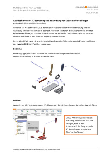
Transcription
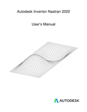
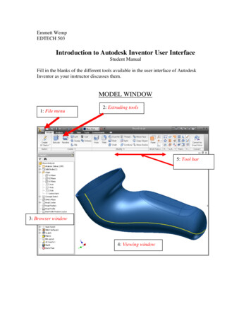
Emmett WempEDTECH 503Introduction to Autodesk Inventor User InterfaceStudent ManualFill in the blanks of the different tools available in the user interface of AutodeskInventor as your instructor discusses them.MODEL WINDOW1: File menu2: Extruding tools5: Tool bar3: Browser window4: Viewing window
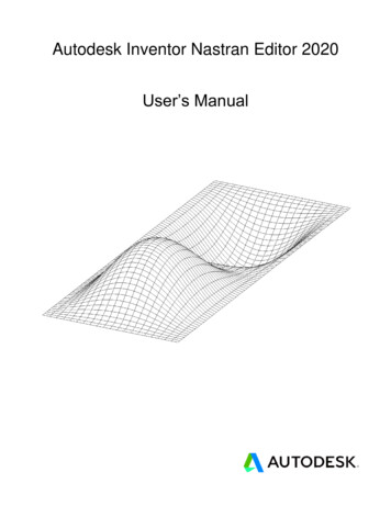
SKETCH WINDOW1: Drawing tools2: Pattern tools3: Return tomodel4: Browser window5: Sketch window
2D SketchingStudent ManualMaterials:Computer with Autodesk Inventor installedProcedure:In order to effectively use Autodesk Inventor as a design tool, a designer mustknow what sketching tools are available and how they work. This activity will help youto understand and utilize the sketching tools that are available in Autodesk Inventor.There are 13 exercises in this activity. These exercises require the creation of anew PART file, and the replication of the images pictured. As you finish each exercise,initial the graphic, save the PART file, document the file name and location on the lineprovided, and submit this activity to your instructor for evaluation. This exercise beginson the next page.
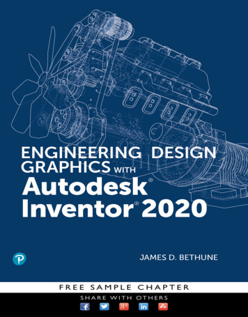
2D SketchingStudent ManualThe spline tool is used to create irregular curves, such as the contour of a car bodysurface. Create a new PART file, and use the spline sketch tool to draw two irregularcurves and two closed shapes that approximate the figures pictured above. Note thelocations and number of points in each spline.PART file name:Create a new PART file and use the circle and ellipse sketch tools to replicate the figuresshown above. Label the images as shown using the text tool.PART file name:
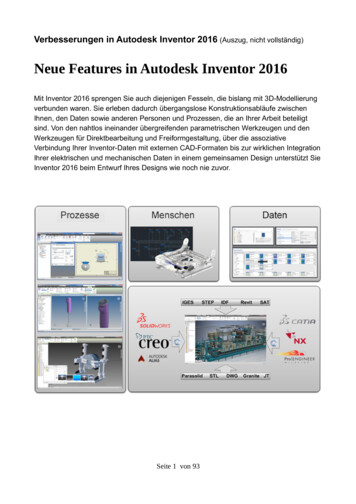
2D SketchingStudent ManualAutodesk Inventor gives the user the ability to define arcs through several methods.These methods may include: defining the size of an arc by establishing three points oftangency, referencing two points of tangency, or identifying a center point and two pointsof tangency. Create a new PART file and use the line and arc sketch tools to replicate thefigures shown above. Label the images as shown using the text tool.PART file name:The fillet tool creates a round where two lines meet at a corner. The size of the round isidentified as a radius value. Create a new PART file and draw a rectangle that isapproximately 2 inches wide by 1.25 inches tall. Use the fillet sketch tool to round off thetop right to .25 inch radius. Then, round off the bottom right corner with a .75 inchradius. Lastly, round off the bottom left hand corner with a .5 inch radius.PART file name:
2D SketchingStudent ManualThe chamfer tool is often used to “break” a corner, which results in a softer edge on apart. This process is typically done in one of three ways: by identifying the distance ofone side of a 45 angle, by identifying the individual lengths of each side of the chamfer,or by identifying length of one side and the angle of the chamfer. Create a new PART fileand draw a rectangle that is approximately 2 inches wide by 1.5 inches tall. Use thechamfer sketch tool and all three methods explained to create angles at the top right andbottom corners of the rectangle according to the dimensions given in the figure shownabove.PART file name:Regular polygons are multisided shapes that have sides of equal length. They may beinscribed or circumscribed within a given radius. The raw materials that are used toproduce engineered objects are often manufactured in the shape of regular polygons.Create a new PART file and use the polygon sketch tool to draw the series of shapespictured above. Use the text tool to label the names of each of the regular polygons.PART file name:
2D SketchingStudent ManualBeforeAfterAutodesk Inventor allows the designer to mirror images across lines, which is a usefultool when designing parts that have high degrees of symmetry. Create a new PART fileand use the line and circle sketch tools to create a similar figure to the one shown in theBefore image. A regular vertical line may be used as the mirror line. The top and bottomhorizontal edges must terminate at the vertical mirror line. Use the mirror sketch tool tomirror the figure across the mirror line.PART file name:BeforeAfterThe ability to pattern a shape or element allows the designer to save time and maintainaccuracy. Create a new PART file and draw a circle with a diameter of approximately2.25 inches. Use the polygon sketch tool to create an isosceles triangle that would fitwithin a .25 inch diameter circle. Orient the triangle so that it is pointing toward the topquadrant of the circle. The center of the triangle should be approximately 7/8 inch fromthe center of the circle. Use the pattern sketch tool to create a copy of the triangle 12times (the number of instances includes the object being patterned) around the center ofthe circle.PART file name:
2D SketchingStudent ManualBeforeAfterThe Pattern sketch tool allows the designer to create a pattern from one or several objects.The direction or orientation of the pattern is derived from existing lines on the sketch.Create a new PART file and draw a rectangle that is approximately 4 inches wide by 3.25inches tall. Create a 3/8 inch diameter circle in the lower left hand corner. Locate thecenter of the circle approximately 3/8 inch from the bottom and left edges. Use thepattern sketch tool to create multiple copies of the circle. The circle pattern must haveseven columns and six rows, and fit within the boundaries of the rectangle.PART file name:BeforeAfterThe need to create geometry that is identical in shape and parallel is very common inengineering design. The Offset sketch tool is used to make this process quick andaccurate. Create a new PART file and draw the figures pictured in the before image. Usethe Offset sketch tool to offset the geometry of each figure outward two times.PART file name:
2D SketchingStudent ManualBeforeAfterCreate a new PART file and draw the figures pictured in the before image. Use the Trimsketch tool and delete keyboard function to make the before image look like the afterimage.PART file name:BeforeAfterCreate a new PART file and draw the figures pictured in the before image. Use theExtend sketch tool to extend the straight lines to the spline. When finished, the sketchshould look like the after image.PART file name:
2D SketchingStudent ManualBeforeAfterCreate a new PART file and draw the figures pictured in the before image. Use the Movesketch tool to move the geometric shapes to the positions shown in the after image.PART file name:
3D ModelingStudent ManualEquipment Computer with Autodesk Inventor installedPART files located on Student Resource larPatternLoftThreaded rodFillets-chamfersLeft halfProcedureThis activity will help you to understand and utilize the feature tools used inAutodesk Inventor.There are 8 exercises in this activity which represent the different feature toolsavailable to use in Autodesk Inventor. You will need to open the files provided from thestudent resource CD. As you finish each exercise, initial the graphic, save the PART file,document the file name and location on the line provided, and submit this activity to yourinstructor for evaluation.
Mid plane ExtrusionsThe mid plane extrusion function will join, cut, or intersect the selected sketch equaldistances in both directions from the selected profile. Open the file Mid-plane, andperform a 1 inch mid plane extrusion on the sketch. (note: the extrusion can occur in onedirection or the other if a mid plane in not desired) Save the file as a different name.PART file name:Revolve this sketchAround thisaxisRevolveRevolve is a function that allows the user to extrude a closed profile around a fixed axisup to 360 . The axis can be part of the profile, an existing edge on a part, or one of theaxes of the Cartesian coordinate grid. Grid axes may be selected from the Origin folderlocated in the Browser bar. Open the file called Bushing. Use the revolve function torevolve the sketch around the existing axis a full 360 . Save the file as a different name.PART file name:
LoftSketches ondifferent planesThe loft function allows the user to create a solid by blending two or more closedsketches that are located on different planes. Open the file called Loft. Use the loftfunction to blend the three sketched profiles into one solid object. Save the file as adifferent name.PART file name:Circular Patternpattern thisfeatureAround thisaxisThe pattern function allows the user to make multiple copies of an existing feature in oneof three ways. A circular pattern is often used to pattern a hole around a center axis. Anedge on an existing feature can also serve as the center axis. Open the file calledCircularPattern, and use the circular pattern function to copy the existing hole on theflange plate a total of 10 times (the first hole must be represented in the count) around theexisting axis. Save the file as a different name.PART file name:
Rectangular PatternHorizontaldirection 1Feature topatternVerticaldirection 2The rectangular pattern function allows the user to make copies of an existing feature inone direction, or two directions simultaneously. Existing edges must be selected toidentify the desired direction(s). Open the file called RectangularPattern. Use therectangular pattern to copy the existing cylindrical extrusion six times in the horizontaldirection and four times in the vertical direction. Save the file as a different name.PART file name:
ThreadClick on the face ofthe cylinderThe thread function allows the user to simulate the appearance of threads on the curvedsurface of either a cylinder or a hole. This will aid in calling out the dimensions later inthe documentation process. The diameter of the cylinder or hole must match the nominaldiameter of the desired thread form. Open the file called ThreadedRod. Use the threadfunction to place a right-hand 5/8-11 UNC thread along the entire length of the cylinder’scurved face. Save the file as a different name.PART file name:
FilletPlace fillets on theseedges by selectingthemFillet is a function that allows the user to create a rounded edge where two surfaces meetto form an edge. It should be noted that on an exterior corner, the resulting feature isknown as a round. On an interior corner, the resulting feature is known as a fillet. Thefillet tool is used for both features. Open the file called Fillets Chamfers. Use the filletfunction to apply a .25 radius to the corners shown above. This model will be used in thenext exercise.ChamferChamfer theseedgesChamfer is a function that allows the user to apply an angle surface where two existingsurfaces meet to form an edge. Use the chamfer function to apply a .25 inch x 45 chamfer to the edges shown above on the file from before. Save the file as a differentname.PART file name:
MirrorMirror is a function that allows the user to create a mirror image of existing geometry.This function requires an existing feature(s) and a surface or work plane to serve as themid-plane of symmetry. Open the file called LeftHalf. Use the mirror function to add aduplicate mirror image of the existing geometry on the other side of the right face of theobject. Save the file as a different name.PART file name:
AssessmentStudent GuideMaterials:Computer with Autodesk Inventor installedStudent ManualProcedure:In this assessment, you will create computer models of different objects. You willwrite step-by-step instructions on how to create one of your objects and give them to aclassmate to create from your instructions. The teacher will assign the object for whichyou will need to write the directions. Create nine of the eleven objects located below using Autodesk Inventor. Create a set of step-by-step instructions on how an object was created usingAutodesk Inventor. The instructor will determine the object for which youwill write the instructions. Trade your instructions with a classmate and create his or her object.
Student Manual Autodesk Inventor gives the user the ability to define arcs through several methods. These methods may include: defining the size of an arc by establishing three points of tangency, referencing two points of tangency, or identifying a center point and two points of tangency. Create a new PART file and use the line and arc sketch tools to replicate the