Transcription
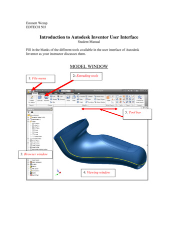
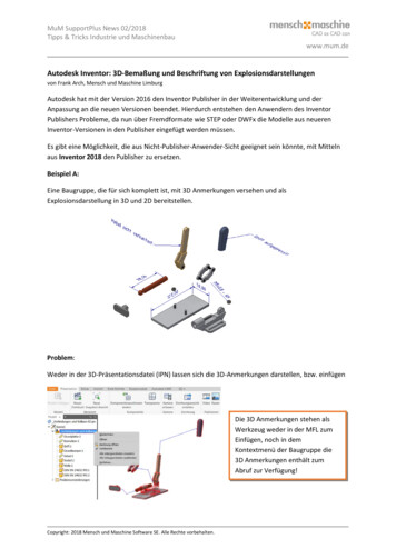
Introduction toAutodesk Inventor forF1 in Schools F1 in Schools race car In this course you will be introduced to Autodesk Inventor , which is the centerpiece of Autodesk’s DigitalPrototyping strategy that allows you to create and simulate a design before it is made. Autodesk Inventor isa 3D parametric modeler that allows you to easily create and modify a design. In this fun and excitinghands-on course, you will learn the basic design workflow by modeling and documenting an F1 in Schools race car.Autodesk Education
Table of ContentsCourse objectives . 3Student notice . 3 Free Autodesk software . 3Screen setup . 4Chapter 1 – Part modeling . 5Exercise 1: Section 1 – Getting started. 5Exercise 1: Section 2 – Define the car body’s shape . 12Exercise 1: Section 3 – CO2 cartridge and wings . 16Exercise 1: Section 4 – Final features . 23Chapter 2 – Creating a drawing . 30Exercise 2: Section 1 – Creating drawing views . 30Exercise 2: Section 2 – Drawing annotation . 38Exercise 2: Section 3 – Editing the model . 45Chapter 3 – Assembly . 48Exercise 3 – Assembling an F1 in Schools race car . 48Chapter 4 – Visualization . 54Exercise 4 – Additional visualization options . 542
Course objectivesAfter completing this course, you will be able to: Model an F1 in Schools race car Create drawing views of an F1 in Schools race car Assemble an F1 in Schools race car Enhance the visual appeal of the car by changing the visual style of the car, adding a decal, shadows andreflections, changing the background and ground plane and adjusting the light sourcesStudent noticeThe design and dimensions shown in this course are for demonstration purpose only.Check the F1 in Schools technical rules and regulations for design and dimension specifications.Dataset filesDownload the dataset file Inventor Course F1 in Schools Dataset.zip. Then extract the files, the defaultlocation is C:\F1 in Schools.Free Autodesk softwareAutodesk is pleased to support your design efforts by making our industry leading 3D design softwareproducts available to students for free. Register and download software from http://students.autodesk.com.AuthorDan Banach, Autodesk EducationTechnical EditorsDoris Fischer, Autodesk EducationMatthew Bell, Autodesk Education3
Screen setupAnother option to go through this tutorial is to open the Introduction toAutodesk Inventor F1 in Schools Screen Version.pdf that is located where you downloaded the datasetfiles. Then position Autodesk Inventor and the PDF on one screen and then scroll through the PDF as youprogress.4
Chapter 1 – Part modelingExercise 1: Section 1 – Getting startedIn this section you start to define the shape of the car body.1) First you set where Inventor will look for files and where files will be saved. Set the active project by clickingthe Projects command either on the Welcome screen or on the Get Started tab Launch panel.a)Click the Browse button at the bottom of the Project dialog box.b)Navigate to the location where the exercise file were saved (the default location is C:\F1 in Schools)and double click on F1 in Schools.ipj.c)In the Projects dialog box, a check mark should be to the left of the F1 in Schools project name,verifying that this is the active project file.2) The first step is to create a new part file, click the New command on the Welcome dialog box or on theQuick Access toolbar.a)In the Create New File dialog box click the Metric folder under Templates, labeled (1).b)Double-click on Standard (mm).ipt, labeled (2).3) First you define where you will sketch the profile of the car. Create a new sketch by right-clicking on a blankarea in the graphics window and click New Sketch on the marking menu.5
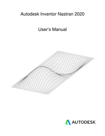
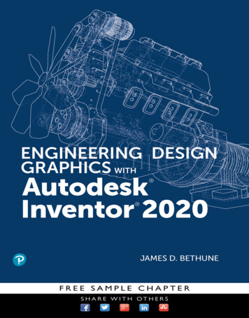
4) In the graphics window select the XY origin plane.5) Sketch the profile (outline) of the side view of the car body by right-clicking on a blank area in the graphicswindow and click Create Line on the marking menu, or press the L key or click Sketch tab Draw panel Line.6a)Click on the Origin point (0,0) in the middle of the screen, a green circle will appear when on the originpoint.b)Enter a value of 200 mm in distance value cell.c)Press the TAB key to lock in this value.d)Move the cursor to the right and when the horizontal symbol appears, click in the graphics window.e)Enter a value of 20 mm in distance value cell.f)Press the TAB key to lock in this value.g)Move the cursor to up and when the perpendicular symbol appears, click in the graphics window.h)Enter a value of 90 mm in the distance value cell.
i)Press the TAB key to lock in this value.j)Move the cursor to the left and when the parallel symbol appears, click in the graphics window.k)Next you sketch an arc while in the line command. While still in line command, click on the left endpointof a top horizontal line and a small gray circle will appear.l)Click on the small circle, and with the left mouse button pressed down, move the cursor down and tothe left until it is directly above the origin point and click. When done, there should be a gap betweenthe endpoint of the arc and the origin point.m) Close the profile by clicking on the origin point.n)Finish the Line command by right-clicking on a blank area in the graphics window and click OK on themarking menu.6) When sketching, you want to fully constrain sketches by adding constraints and dimensions. Notice on thelower corner of Inventor’s Status Bar Inventor tells you how many dimensions or constraints are required tofully constrain the sketch.7) Next you add the missing dimension. Start the dimension command by right-clicking on a blank area in thegraphics window and click General Dimension on the marking menu, or press the D key or click Sketch tab7
Constrain panel Dimension.a)In the graphics window, select the left vertical line, and then move the cursor to the left and then click toplace the dimension.b)Change the length of the line by entering 8 in the Edit Dimension dialog box and then press ENTER orclick the green check mark in the dialog box. Since no unit was entered, the default unit of thedocument will be used, in this case is millimeters.8) Next you move the 200 mm dimension, as it is goes through the geometry.a)Press the Esc key to exit the Dimension command.b)Move the cursor over the 200 mm dimension until the four arrows appear, and then click and drag thedimension below the bottom horizontal line.9) The sketch dimensions are parametric, meaning that the value of the dimension controls the size of thegeometry. Change the size of the 200 mm by double-clicking on it and enter 250 in the Edit Dimensiondialog box and then press Enter or click the green check mark in the dialog box.10) Change the 250 mm dimension back to 200 mm by double-clicking on the 250 mm dimension and enter 200in the Edit Dimension dialog box and then press Enter.11) Exit the sketch environment by right-clicking on a blank area in the graphics window and click Finish 2DSketch on the marking menu or click Sketch tab Exit panel Finish Sketch.12) If needed, scroll the wheel on the mouse to zoom in and out. Hold down the wheel on the mouse to pan thescreen.13) Next you extrude the profile to create one half of the car body. Start the extrude command by clicking on anygeometry in the sketch and click Create Extrude from the mini-toolbar, or press the E key or click 3D Model8
tab Create panel Extrude.a)Next you extrude the profile one half of its overall width, which will be 70 mm. In the value area in themini-toolbar you can enter 35 or 70/2 and then press ENTER or click the green check mark in the minitoolbar.14) Next you remove material to refine the shape the car body.a)9Rotate the viewpoint so you can see the bottom of the car by pressing down the F4 key and click anddrag inside the circle that appears in the middle of the screen and then release the F4 key.TIP: to change the viewpoint you can also use the Free Orbit command on the Navigation bar,which is on the right side of the screen.
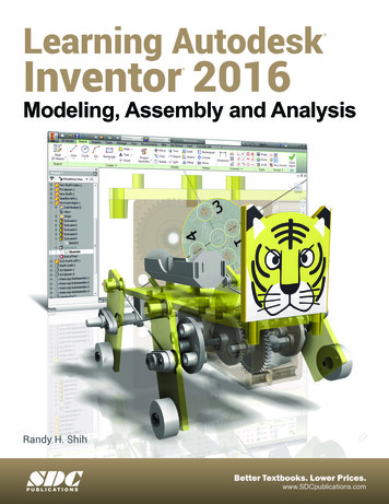
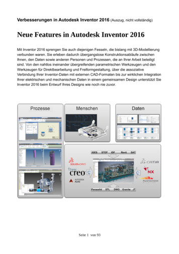
b)Create new sketch by clicking on the bottom plane and click the Create Sketch on the mini-toolbar.15) Sketch for the area that will be removed, right-click on a blank area in the graphics window and click CreateLine on the marking menu and select on the left-vertical line about a quarter of the way up and create a 50mm line.a)While still in the line command, click on the right endpoint of the line and a small gray circle will appear.Click on the small circle, and with the left mouse button pressed down, move the cursor up and to theright until it is touches the top horizontal line and click.b)Start the dimension command and add a 10 mm linear and 120 mm radius dimension as shown.16) Next draw a rectangle by right-clicking on a blank area in the graphics window and click Two PointRectangle on the marking menu, or click Sketch tab Draw panel Rectangle.10
a)Place the first point of the rectangle by clicking on the upper-right corner of the sketch. When the cursoris over the corner, a green circle appears, indicating a coincident constraint will be applied (the pointsare tied to each other).b)Move the cursor down and to the left and enter 40 and press the Tab key to lock in the dimension.c)Enter 16 and press the Tab key to lock in the dimension and then press Enter to create the fullyconstrained rectangle.d)Exit the sketch environment by right-clicking on a blank area in the graphics window and click Finish 2DSketch on the marking menu or click Sketch tab Exit panel Finish Sketch.e)Next you extrude the profile to remove material from the car body. Start the extrude command byclicking on any geometry in the sketch and click Create Extrude from the mini-toolbar, or press the Ekey or click 3D Model tab Create panel Extrude.f)Since there are multiple closed profiles select in the top two areas that you sketched to remove materialfrom, labeled (1).g)In the mini-toolbar or Extrude dialog box change the Extents to All, labeled (2).h)In the mini-toolbar or Extrude dialog box change the Operation to Cut, labeled (3).i)Complete the command by clicking the green check mark in the mini-toolbar or click OK in the Extrudedialog box.17) Save the file by clicking the Save command on the Quick Access toolbar and enter F1 Car Body for the filename.11
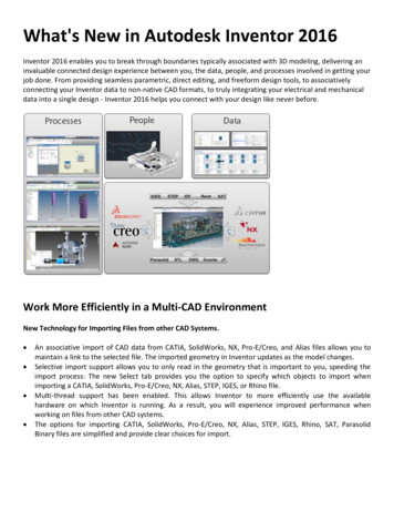
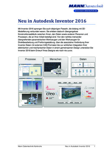
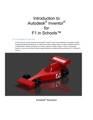
Exercise 1: Section 2 – Define the car body’s shapeIn this section you create a wheel extension that will extend the wheel away from the body.Continue working on the same file or if you were not able to complete the previous section, open the file Ex1Sec2 F1 Car Body.ipt.121)Create new sketch by clicking on the back planar face and click Create Sketch on the mini-toolbar.2)Next draw a circle by right-clicking on a blank area in the graphics window and click Center Point Circle onthe marking menu, or press the C key or click Sketch tab Draw panel Circle.a)Locate the circle by clicking a point on the right side of the planar face.b)Enter 8 for the diameter.c)Create the circle by pressing the Enter key.3)Start the dimension command and add an 8 mm and 40 mm dimension as shown.4)Finish the sketch and extrude the circle 20 mm, click inside the circle to define the profile to extrude.
5)6)7)13If needed you can edit the sketch by selecting on the face of the feature. In this step you edit the sketch ofthe extruded circle. Select the circular face of the extruded circle and click Edit Sketch on the mini-toolbar.a)Double-click on the 8 mm diameter dimension and change its value to 6 mm.b)Click the green check mark in the Edit Dimension dialog box and the sketch should resemble thefollowing image.c)Exit the sketch environment by right-clicking on a blank area in the graphics window and click Finish 2DSketch on the marking menu or click Finish Sketch on the Sketch tab Exit panel.You can also edit a feature selecting on the face of the feature. In this step you edit the extruded distance ofthe circle. Select the circular face of the extruded circle and click Edit Extrude on the mini-toolbar.a)Change distance to 10 mm.b)Com
Then position Autodesk Inventor and the PDF on one screen and then scroll through the PDF as you progress. 5 Chapter 1 – Part modeling Exercise 1: Section 1 – Getting started In this section you start to define the shape of the car body. 1) First you set where Inventor will look for files and where files will be saved. Set the active project by clicking the Projects command either on the .