Transcription
ElectronicsWorkbenchTMMultisim 8 Simulation and CaptureTMGetting Started GuideTitleShort-Hidden (cross reference text)May 2005371589A-01
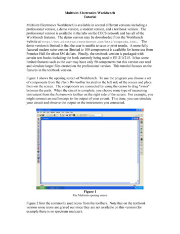
Quick Start with Multisim 8This booklet leads you through the circuit design flow, from schematic capture,through simulation and analysis. You will design and test a circuit that samplesa small analog signal, amplifies it and then counts the occurrences of the signalon a simple digital counter.Schematic CaptureIn this section, you will place and wire the components in the circuit shownbelow.Saving the FileWhen you first launch Multisim, the program opens a blank file on theworkspace called “Circuit1”.To save the default file with a new name:1. Select File/Save to display a standard Windows Save dialog.2. Navigate to the location where you want to store the file, and enter“MyQuickStart” as the filename, and click on the Save button.To guard against accidental loss of data, you can set up a timed auto-backupof the file in the Save tab of the Global Preferences dialog box.To view files from earlier versions of Multisim, select the desired version in theFiles of Type drop-down in the Open dialog.—2—
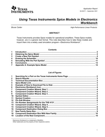
Placing the Components1. Select Place/Component to display the Select a Component browser, navigateto the 7-segment LED display as shown below and click OK. The componentappears as a “ghost” on the cursor.Once you have selected the desired Group and Family, you can start typingthe component’s name. In the above example, type SEVEN SEG DECIMALCOM A BLUE. Matches are displayed as you type.2. Move the cursor to the bottom-right area of the workspace and left-click toplace the component. Note that the Reference ID for this component is “U1”.3. Place the remaining components in the Digital Counter area as shown below.As you place the 200-ohm resistor, rotate it to a vertical orientation.Hit Ctrl-R as you move it to the desired location.Reference IDs (e.g., U1, U2) are assigned in the order the components areplaced. If you place components in a different order than in the originalcircuit, the numbering will differ. This will not effect the operation of thecircuit in any way.—3—
4. Place the parts in the Counter Control section. After placement, right-clickon each of the SPDT switches and select Flip Horizontal.The SPDT switches are in the Basic Group;Switch Family.When a part is on the workspace and you wantto place the same part again, highlight it andselect Edit/Copy, then Edit/Paste.5. Place the parts in the Analog Amplifier and Bypass Capacitors section asshown below, rotating as needed.After you place the AC voltage signal source, double-click on it. Change theVoltage (Pk) to 0.2 V and click OK to close the dialog.6. Place the header and associated parts as shown below.J3 is in the Basic Group; Connectors Family.Once you have wired a circuit, you can droptwo-pinned passive components like resistorsdirectly onto a wire. Multisim automaticallymakes the connection.Wiring the CircuitMultisim is modeless; there is no need to toggle between wiring and partplacement modes. As soon as your cursor is over a pin, Multisim knows you wantto wire and the pointer changes to a crosshair.You can wire the circuit that you placed on the workspace or you can use“QuickStart1.ms8” from the “Samples\QuickStart” folder.—4—
To wire the circuit:1. Click on a pin on a component to start the connection and move the mouse.A wire appears, attached to your cursor.2. Click on the destination pin to finish the connection. Multisimautomatically and intelligently places the wire.3. You can manually control the flow of the wire by clicking on points as youmove the mouse. Each click “fixes” the wire to that point.4. Wire the Digital Counter section as shown below.Use Bus Vector Connect to wire multi-pinned devices like U3 and U1 together.Refer to the Helpfile for details.Virtual Wiring — To avoid clutter, you could use virtual connections betweenthe Counter Control and Digital Counter sections. When two nets have thesame name, they are virtually connected.5. Finish wiring the circuit as shown below.—5—
SimulationIn this section, you will use a virtual instrument and interactive components tosimulate the design. You will explore the circuit behavior using analysis.You can simulate the circuit that you placed and wired or you can use“QuickStart2.ms8” from the “Samples\QuickStart” folder.Virtual Instrumentation1. J1, J2 and R2 are interactive components.Set up the interactive keys for the components by double-clicking on each.In the Key field, enter “E” for J1, “L” for J2, and “A” for R2.Press the “E” key on your keyboard to enable the counter.2. Select Simulate/Instruments/Oscilloscope to place the oscilloscope on theworkspace. Wire the instrument as shown in Step 4.To change the color of traces on the oscilloscope, right-click on the wireconnected to the scope’s input and select Segment Color from the pop-up.3. Double-click on the scope’s icon to show the instrument face. SelectSimulate/Run. The output of the operational amplifier appears on the scope.4. Adjust the Timebase to 2mS/Div and Channel A’s Scale to 500mV/Div.As the circuit simulates, the 7-segment display counts up and the LEDflashes at the end of each count cycle.5. Press “E” on your keyboard while the simulation is running to enable ordisable the counter.Press “L” to load zeros into the counter.Press “Shift-A” to observe the effect of changing the potentiometer’s settingon the oscilloscope. Repeat, pressing “A”.Remember to click on the schematic or the interactive components’ keyswill not work.—6—
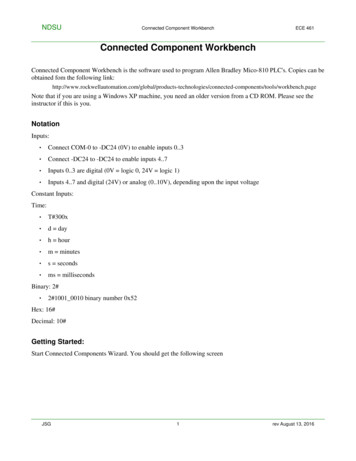
AnalysisFor this circuit, you will use AC Analysis to verify the frequency response of theamplifier.1. Double-click on the wire that is attached to pin 6 of the op-amp, and changethe net name to “analog out” in the Net dialog box.2. Select Simulate/Analyses/ACAnalysis; click on the OutputVariables tab.3. Highlight analog out in theleft column and click Add. analog out moves to the rightcolumn. Remove other tracesfrom the right column.4. Click Simulate. The results ofthe analysis appear in the Grapher.The GrapherThe Grapher is a multi-purpose display tool that lets you view, adjust, save andexport graphs and charts. It displays the results of all Multisim analyses ingraphs and charts and a graph of traces for some instruments. Refer to theHelpfile for details. Select View/Grapher after running a simulation.ConclusionElectronics Workbench understands that it requires valuable time to learn a newsoftware program, or application. This manual helps guide you through onlythe most commonly used features in Multisim 8. We also recommend that youcarefully read the User Guide that has been provided on CD and within theHelpfile.—7—
Installing Multisim 8Before installing the software, please read the detailed installationinstructions found in the Multisim 8 User Guide (found on the separateProduct Documentation CD).The software CD autoruns when inserted. If it does not autorun, chooseRun from the Windows Start menu, type “d:\autorun” at the prompt andclick OK. The software installer appears.Follow the on-screen prompts to install the software. 2004 Interactive Image Technologies. All rights reserved. Electronics Workbench, Multisim and Ultiboard are registered trademarks of Interactive Image Technologies Ltd.All other trademarks are property of their respective owners.8.0.0.1204
When you first launch Multisim, the program opens a blank file on the workspace called "Circuit1". To save the default file with a new name: 1. Select File/Save to display a standard Windows Save dialog. 2. Navigate to the location where you want to store the file, and enter "MyQuickStart" as the filename, and click on the Save button.