Transcription
IAR Embedded Workbench Version 7 for MSP430 User's GuideLiterature Number: SLAU138APJune 2004 – Revised November 2017
ContentsPreface . 51Get Started Now! . 71.11.22Development Flow . 102.12.22.32.42.52.62.72.82.92.102.113Software Installation . 8Flashing the LED . 8Overview.Project Settings .Using Math Library for MSP430 (MSPMathlib) in IAR EW430 5.60.1 and Newer .Additional Project Settings for MSP430L092 and MSP430C092 .2.4.1 MSP430L092 Loader Code .2.4.2 Password Protection of MSP430C092 .Creating a Project From Scratch .Additional Project Settings for Ultra-Low-Power Mode (LPMx.5) Debugging .2.6.1 What is LPMx.5 .2.6.2 Debugging LPMx.5 Mode on MSP430 Devices That Support the Ultra-Low-Power Debug Mode .2.6.3 Debugging LPMx.5 Mode on MSP430 Devices That Do Not Support the Ultra-Low-Power DebugMode .Password Protection for MSP430 Devices .Stack Management and .xcl Files .How to Generate TI .TXT (and Other Format) Files .Overview of Example Programs .Using C-SPY .2.11.1 Breakpoint Types .2.11.2 Using Breakpoints .2.11.3 Using Single Step .2.11.4 Using Watch Windows ce Technology. 243.13.23.33.43.5Introduction .Energy Measurement .IAR Embedded Workbench for MSP430 Integration .3.3.1 Debugging Devices With EnergyTrace Technology Support .3.3.2 Debugging Devices Without EnergyTrace Technology Support .Measuring Low-Power Currents .EnergyTrace Technology FAQs .242424243134354Memory Protection Unit (MPU) and Intellectual Property Encapsulation (IPE) . 38AFrequently Asked Questions . 40A.1A.2A.3BFET-Specific Menus . 47B.12Hardware . 41Program Development (Assembler, C-Compiler, Linker) . 41Debugging (C-SPY) . 43Menus .B.1.1 Emulator Device Information .B.1.2 Emulator Release JTAG on Go .B.1.3 Emulator Resynchronize JTAG .Contents47474747SLAU138AP – June 2004 – Revised November 2017Submit Documentation FeedbackCopyright 2004–2017, Texas Instruments Incorporated
11B.1.12B.1.13B.1.14B.1.15B.1.16B.1.17Emulator Init New Device .Emulator Secure - Blow JTAG Fuse .Emulator Breakpoint Usage .Emulator Advanced Clock Control .Emulator Advanced Emulation Mode .Emulator Advanced Memory Dump .Emulator Advanced Breakpoint Combiner.Emulator State Storage Control .Emulator State Storage Window .Emulator Sequencer Control .Emulator "Power on" Reset .Emulator GIE on/off .Emulator Leave Target Running .Emulator Force Single Stepping .4747474748484848484848484848Revision History . 49SLAU138AP – June 2004 – Revised November 2017Submit Documentation FeedbackCopyright 2004–2017, Texas Instruments IncorporatedContents3
www.ti.comList of FiguresActivate Project1-2.Activate Project in Workspace Overview . 92-1.L092 Mode . 132-2.C092 Emulation Mode . 142-3.C092 Password . 142-4.Enable Ultra-Low-Power Debug Mode . 162-5.LPMx.5 Notifications . 172-6.JTAG Password . 183-1.Pulse Density and Current Flow . 243-2.Debug Session With EnergyTrace Windows . 253-3.Debug Options . 263-4.Emulator Pulldown Menu With EnergyTrace -Related nabling the State Log Window .State Log Window With EnergyTrace Data .State Log Summary With EnergyTrace Data .Power Log Setup Window.Power Log Window With EnergyTrace Data .Timeline With Power Log and State Graphs Disabled .Timeline With EnergyTrace Data .Function Profiler With EnergyTrace Data .Debug Session With EnergyTrace Windows .Emulator Pulldown Menu With EnergyTrace-Related Functions.Power Log Setup Window.Power Log Window With EnergyTrace Data .Timeline With Power Log Graph Disabled .Timeline With EnergyTrace Data .LPM3 Current When Executing Under Debug Control .Release JTAG on Go Option in Emulator Pulldown Menu .LPM3 Current When Executing with JTAG Signals Released .MPU Configuration Dialog .List of 138AP – June 2004 – Revised November 2017Submit Documentation FeedbackCopyright 2004–2017, Texas Instruments Incorporated
PrefaceSLAU138AP – June 2004 – Revised November 2017Read This FirstTrademarksMSP430, E2E, EnergyTrace are trademarks of Texas Instruments.IAR Embedded Workbench is a registered trademark of IAR Systems.ThinkPad is a trademark of IBM.Intel is a registered trademark of Intel Corporation.Motorola is a trademark of Motorola Corporation.All other trademarks are the property of their respective owners.About This ManualThis manual describes the use of IAR Embedded Workbench (EW430) with the MSP430 ultra-lowpower microcontrollers.How to Use This ManualRead and follow the instructions in Get Started Now!. This chapter provides instructions on installing thesoftware, and describes how to run the demonstration programs. After you see how quick and easy it is touse the development tools, TI recommends that you read all of this manual.This manual describes only the setup and basic operation of the software development environment, but itdoes not fully describe the MSP430 microcontrollers or the complete development software and hardwaresystems. For details of these items, see the appropriate TI and IAR documents listed in RelatedDocumentation From Texas Instruments.This manual applies to the use of the TI MSP-FET, TI MSP-FET430UIF, MSP-FET430PIF, and eZ430development tools series.These tools contain the most up-to-date materials available at the time of packaging. For the latestmaterials (including data sheets, user's guides, software, and application information), visit the TI MSP430website at www.ti.com/msp430 or contact your local TI sales office.Information About Cautions and WarningsThis book may contain cautions and warnings.CAUTIONThis is an example of a caution statement.A caution statement describes a situation that could potentially damage yoursoftware or equipment.WARNINGThis is an example of a warning statement.A warning statement describes a situation that could potentiallycause harm to you.The information in a caution or a warning is provided for your protection. Read each caution and warningcarefully.SLAU138AP – June 2004 – Revised November 2017Submit Documentation FeedbackCopyright 2004–2017, Texas Instruments IncorporatedRead This First5
Related Documentation From Texas Instrumentswww.ti.comRelated Documentation From Texas InstrumentsMSP430 development tools documentation:MSP430 Hardware Tools User's GuideeZ430-F2013 Development Tool User's GuideeZ430-RF2480 User's GuideeZ430-RF2500 Development Tool User's GuideeZ430-RF2500-SEH Development Tool User's GuideeZ430-Chronos Development Tool User's GuideMSP Debugger's User's GuideMSP430 device documentation:MSP430x1xx Family User's GuideMSP430x2xx Family User's GuideMSP430x3xx Family User's GuideMSP430x4xx Family User's GuideMSP430x5xx and MSP430x6xx Family User's GuideMSP430FR57xx Family User's GuideMSP430FR58xx, MSP430FR59xx, MSP430FR68xx, and MSP430FR69xx Family User's GuideCC430 device documentation:CC430 Family User's GuideIf You Need AssistanceSupport for the MSP430 devices and the FET development tools is provided by the TI Product InformationCenter (PIC). Contact information for the PIC can be found on the TI website at www.ti.com/support. TheTI E2E Community for the MSP430 is available to provide open interaction with peer engineers, TIengineers, and other experts. Additional device-specific information can be found on the MSP430 website.6Read This FirstSLAU138AP – June 2004 – Revised November 2017Submit Documentation FeedbackCopyright 2004–2017, Texas Instruments Incorporated
Chapter 1SLAU138AP – June 2004 – Revised November 2017Get Started Now!This chapter provides instruction on installing the software, and shows how to run the demonstrationprograms.Topic1.11.2.PageSoftware Installation. 8Flashing the LED . 8SLAU138AP – June 2004 – Revised November 2017Submit Documentation FeedbackCopyright 2004–2017, Texas Instruments IncorporatedGet Started Now!7
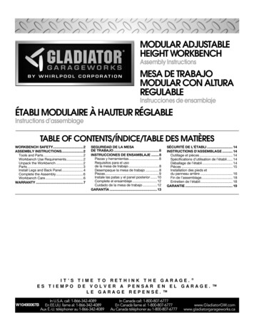
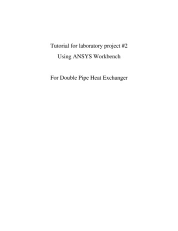
Software Installation1.1www.ti.comSoftware InstallationFollow the instructions on the supplied READ ME FIRST document to install the IAR EmbeddedWorkbench . Read the file Installation Root \EmbeddedWorkbenchx.x\common\doc\EW QuickReference LMS2.ENU.pdf from IAR for the latest information aboutthe Workbench.To install and run IAR Embedded Workbench, you need the following: A Pentium-compatible PC with Microsoft Windows Vista (SP2), Windows 7, Windows 8, Windows 8.1,or Windows 10. Both 32- and 64-bit variants of Windows are supported. Internet Explorer 7 or higher At least 2GB of RAM and 10GB of free disk space Adobe Acrobat Reader to access the product documentationNOTE: If the MSP-FET or eZ-FET debugger driver install fails:Under certain conditions (depending on the hardware and operating system that is used), theMSP-FET or eZ-FET driver install may fail on the first attempt. This can lead to unresponsivebehavior on IDEs. To resolve this issue, disconnect the MSP-FET or eZ-FET and then plug itagain, or plug it in to a different USB port, and restart the IDE.1.2Flashing the LEDThis section demonstrates on the FET the equivalent of the C-language "Hello World!" introductoryprogram. An application that flashes the LED is developed and downloaded to the FET, and then run.1. Start the Workbench (Start Programs IAR Systems IAR Embedded Workbench for MSP430Vxx IAR Embedded Workbench).2. Click File Open Workspace to open the file at: Installation Root \Embedded Workbenchx.x\430\examples\Flashing the LED\Flashing the LED.eww. The workspace window opens.3. Click on the tab at the bottom of the workspace window that corresponds to the MSP430 device(MSP430xxxx) and desired language (assembler or C) to set a project active (see Figure 1-1).Figure 1-1. Activate Project8Get Started Now!SLAU138AP – June 2004 – Revised November 2017Submit Documentation FeedbackCopyright 2004–2017, Texas Instruments Incorporated
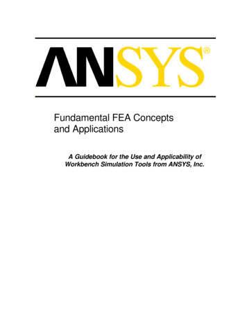
Flashing the LEDwww.ti.comAlternatively, right-click to activate a project in the Workspace Overview tab (see Figure 1-2).Figure 1-2. Activate Project in Workspace Overview4. Click Project Options Debugger Setup FET-Debugger5. Click Project Rebuild All to build and link the source code. You can view the source code by doubleclicking on the project, and then double-clicking on the displayed source file.6. Click Project Download and Debug (CTRL D) to start the C-SPY debugger. C-SPY erases thedevice flash and then downloads the application object file to the device flash.See FAQ Debugging #1 if C-SPY is unable to communicate with the device.7. Click Debug Go to start the application. The LED should flash.8. Click Debug Stop Debugging to stop debugging, to exit C-SPY, and to return to the Workbench.9. Click File Exit to exit the Workbench.Congratulations, you have just built and tested an MSP430 application!SLAU138AP – June 2004 – Revised November 2017Submit Documentation FeedbackCopyright 2004–2017, Texas Instruments IncorporatedGet Started Now!9
Chapter 2SLAU138AP – June 2004 – Revised November 2017Development FlowThis chapter describes how to use IAR EW430 to develop application software and how to use C-SPY todebug view .Project Settings .Using Math Library for MSP430 (MSPMathlib) in IAR EW430 5.60.1 and Newer .Additional Project Settings for MSP430L092 and MSP430C092 .Creating a Project From Scratch .Additional Project Settings for Ultra-Low-Power Mode (LPMx.5) Debugging.Password Protection for MSP430 Devices .Stack Management and .xcl Files .How to Generate TI .TXT (and Other Format) Files .Overview of Example Programs .Using C-SPY .Development FlowPage1112131315161818191919SLAU138AP – June 2004 – Revised November 2017Submit Documentation FeedbackCopyright 2004–2017, Texas Instruments Incorporated
Overviewwww.ti.com2.1OverviewApplications are developed in assembler or C using the Workbench, and they are debugged using C-SPY.C-SPY is seamlessly integrated into the Workbench. However, it is more convenient to make thedistinction between the code development environment (Workbench) and the debugger (C-SPY). C-SPYcan be configured to operate with the FET (that is, an actual MSP430 device) or with a software simulatorof the device. IAR EW430 refers to the Workbench and C-SPY collectively.Documentation for the MSP430 family and IAR EW430 is extensive. The MSP430 home page(www.ti.com/msp430) is another source of MSP430 information.The components of IAR EW430 (IDE, debugger, assembler, compiler, linker) are fully documented in Installation Root \Embedded Workbench x.x\common\doc and Installation Root \EmbeddedWorkbench\430\doc.htm files located throughout the EW430 directory tree contain the most up-to-date information andsupplement the PDF files. In addition, EW430 documentation is available online through Help.ToolUser's GuideIDEEW430 IDEGuide.pdfAssemblerEW430 AssemblerReference.pdfCompilerEW430 CompilerReference.pdfC libraryclib.pdfLinker and Librarianxlink.ENU.pdfDebuggingEW430 DebuggingGuide.pdfSLAU138AP – June 2004 – Revised November 2017Submit Documentation FeedbackCopyright 2004–2017, Texas Instruments IncorporatedDevelopment Flow11
Project Settings2.2www.ti.comProject SettingsThe settings required to configure the Workbench and C-SPY are numerous and detailed. Read andthoroughly understand the documentation supplied by IAR when dealing with project settings. Review theproject settings of the supplied assembler and C examples (the project settings are accessed usingProject Options with the project name selected). Use these project settings as templates whendeveloping your own projects. Note that if the project name is not selected when settings are made, thesettings are applied to the selected file (not to the project).The following project settings are recommended or required: Specify the target device (General Options Target Device). Enable the generation of an executable output file (General Options Output Output file Executable). To most easily debug a C project, disable optimization [C/C Compiler Optimizations Size None (Best debug support)]. Enable the generation of debug information in the compiler output (C/C Compiler Output Generate debug information). Specify the search path for the C preprocessor (C/C Compiler Preprocessor Include Paths). Enable the generation of debug information in the assembler output (Assembler Output GenerateDebug Info). Specify the search path for the assembler preprocessor (Assembler Preprocessor IncludePaths). To debug the project using C-SPY, specify a compatible format [Linker Output Format Debuginformation for C-SPY (with runtime control modules or with I/O emulation modules)]. Specify the search path for any used libraries (Linker Config Search paths). Specify the C-SPY driver. Select Project Options Debugger Setup Driver FET Debuggerto debug on the FET (that is, MSP430 device). Select Simulator to debug on the simulator. If FETDebugger is selected, use Project Options FET Debugger Setup Connection to select theappropriate port: Texas Instruments LPT-IF for the parallel FET Interface (MSP-FET430PIF) or TexasInstruments USB-IF for the USB Interface (MSP-FET430UIF) or for the eZ430. Enable the Device Description file. This file makes C-SPY "aware" of the specifics of the device it isdebugging. This file corresponds to the specified target device (Debugger Setup Devicedescription file Override default). Enable the erasure of the Main and Information memories before object code download (FETDebugger Download Erase main and Information memory). To maximize system performance during debug, disable Virtual Breakpoints (FET Debugger Breakpoints Use virtual breakpoints) and disable all System Breakpoints (FET Debugger Breakpoints System breakpoints on).NOTE:Use Factory Settings to quickly configure a project.Use the Factory Settings button to quickly configure a project to a usable state.The following steps can be used to quickly configure a project. Note that the General Options tab does nothave a Factory Settings button.1. Specify the target device (General Options Target Device).2. Enable the generation of an executable output file (General Options Output Output file Executable).3. Accept the factory settings for the compiler (C/C Compiler Factory Settings).4. Accept the factory settings for the assembler (Assembler Factory Settings).5. Accept the factory settings for the linker (Linker Factory Settings).6. Accept the factory settings for C-SPY (Debugger Factory Settings).12Development FlowSLAU138AP – June 2004 – Revised November 2017Submit Documentation FeedbackCopyright 2004–2017, Texas Instruments Incorporated
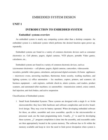
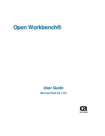
Using Math Library for MSP430 (MSPMathlib) in IAR EW430 5.60.1 and Newerwww.ti.com7. Debug on the hardware (Debugger Setup Driver FET Debugger).8. Specify the active parallel port used to interface to the FET if not LPT1 (FET Debugger Setup Connection Texas Instruments LPT-IF) or specify the USB port (FET Debugger Setup Connection Texas Instruments USB-IF).NOTE:Avoid the use of absolute path names when referencing files.Instead, use the relative pathname keywords TOOLKIT DIR and PROJ DIR . See theIAR documentation for a description of these keywords. The use of relative path namespermits projects to be moved easily, and projects do not require modification when IARsystems are upgraded (for example, from Limited or Baseline to Full).2.3Using Math Library for MSP430 (MSPMathlib) in IAR EW430 5.60.1 and NewerTI's MSPMathlib is part of EW430 5.60.1 and newer releases. This optimized library provides up to 26xbetter performance in applications that use floating point scalar math. For details, see the MSPMathlibweb page (http://www.ti.com/tool/mspmathlib).MSPMathlib may be enabled for new and existing projects on all supported devices. Enable or disableMSPMathlib in the project options (General Options Library Configuration Use TI MathLib).2.4Additional Project Settings for MSP430L092 and MSP430C092The MSP430L092 can operate in two different modes: L092 mode and C092 emulation mode. Thepurpose of the C092 emulation mode is to behave like a C092 with up to 1920 bytes of code at its finaldestination for mask generation.The operation mode is determined by EW430 before starting the debugger. Two radio buttons areavailable for the mode selection. By default the L092 mode is selected (see Figure 2-1 and Figure 2-2).Figure 2-1. L092 ModeSLAU138AP – June 2004 – Revised November 2017Submit Documentation FeedbackCopyright 2004–2017, Texas Instruments IncorporatedDevelopment Flow13
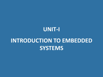
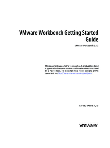
Additional Project Settings for MSP430L092 and MSP430C092www.ti.comFigure 2-2. C092 Emulation Mode2.4.1 MSP430L092 Loader CodeThe Loader Code in the MSP430L092 is a ROM-code from TI that provides a series of services. It enablescustomers to build autonomous applications without needing to develop a ROM mask. Such an applicationconsists of an MSP430 device containing the loader (for example, MSP430L092) and an SPI memorydevice (for example, '95512 or '25AA40); these and similar devices are available from variousmanufacturers.The majority of use cases for an application with a loader device and external SPI memory for native 0.9V supply voltage are late development, prototyping, and small series production.Figure 2-1 shows the selection for loading the application into the external SPI memory.2.4.2 Password Protection of MSP430C092The MSP430C092 is a customer-specific ROM device that is protected by a password. To start a debugsession, the password must be provided to EW430. Figure 2-3 shows how to provide a HEX password inEW430.Figure 2-3. C092 Password14Development FlowSLAU138AP – June 2004 – Revised November 2017Submit Documentation FeedbackCopyright 2004–2017, Texas Instruments Incorporated
Creating a Project From Scratchwww.ti.com2.5Creating a Project From ScratchThis section presents step-by-step instructions to create an assembler or C project from scratch, and todownload and run the application on the MSP430 (see also Section 2.2, Project Settings). The MSP430IAR Embedded Workbench IDE User's Guide presents a more comprehensive overview of the process.1. Start the Workbench (Start Programs IAR Systems IAR Embedded Workbench for MSP430 IAR Embedded Workbench).2. Create a new text file (File New File).3. Enter the program text into the file.NOTE:Use .h files to simplify your code development.IAR EW430 is supplied with files that define the device registers and the bit names for eachdevice. These files can greatly simplify the task of developing your program. The files arelocated in Installation Root \Embedded Workbench x.x\430\inc. Include the .h filecorresponding to your target device in your text file (#include "msp430xyyy.h"). Additionally,files io430xxxx.h are provided and are optimized to be included by C source files.4. Save the program text file (File Save).It is recommended that assembler text files be saved with a file-type suffix of ".s43" and that C text filesbe saved with a file-type suffix of ".c".5. Create a new workspace (File New Workspace).6. Create a new project (Project Create New Project). Select Tool chain: MSP430, Project Templates:Empty project and click OK. Specify a project name and click Save.7. Add the program text file to the project (Project Add Files). Select t
Workbench . Read the file Installation Root \Embedded .pdf from IAR for the latest information about the Workbench. To install and run IAR Embedded Workbench, you need the following: A Pentium-compatible PC with Microsoft Windows Vista (SP2), Windows 7, Windows 8, Windows 8.1, or Windows 10.