Transcription
Application ReportSLOA071 – September 2001Using Texas Instruments Spice Models in ElectronicsWorkbenchBruce CarterHigh-Performance Linear ProductsABSTRACTTexas Instruments provides Spice models for operational amplifiers. These Spice models,however, are in a generic text format. This note describes how to take these models andimport them into a widely used simulation program—Electronics Workbench .ContentsIntroduction . 2Obtaining the Spice Model . 2Create a New Part Symbol . 4Drawing the Schematic . 10Simulating With the Part Symbol . 11Conclusions. 13Appendix A: Example Spice Model. 141234567List of Figures12345678910111213141516171819Searching for a Part on the Texas Instruments Home Page . 2Search Results . 3Technical Documentation Box . 3Spice Model Link. 3Example of How to Download File to Disk . 3Electronics Workbench Icon . 4Component Creation Wizard, Step 1. 4Component Creation Wizard, Step 2. 5Component Creation Wizard, Step 3. 5Symbol Editor. 6Symbol Creation. 6Pin Edit Window . 6Pin Number Assignments for the THS 4131 . 7Component Creation Wizard, Step 4. 7Component Creation Wizard, Step 5. 8Component Destination Dialog Box . 9New Family Name Box . 9Component Destination Box With New Family . 10Location of the New Component. 10Electronics Workbench is a trademark of MultiSim.Other trademarks are the property of their respective owners.1
SLOA071202122231Electronics Workbench Schematic, Using New Symbol . 11AC Analysis Window . 12Output Variables Window. 12Simulation Results. 13IntroductionSpice models have been a mainstay of applications departments at semiconductor companiesfor decades. They have been provided for simulation purposes, and distributed in print, floppydisk—more recently through CDs and the World Wide Web. They are provided in ASCII textformat, which is generic and allows importation into a variety of programs.Unfortunately, the world has long since progressed beyond ASCII text entry Spice. The authorremembers college classes where Spice was implemented on a mainframe. The schematic wasreduced to numbered nodes, and each connection was painstakingly typed onto a punch card. Years later, the schematic was typed into an ASCII .cir file and PSpice was run from DOS, theresulting table of results seemed almost magical.Microsoft Windows introduced a new element to Spice—graphical interface simulation programs.Designers, finally free of the need to meticulously type in ASCII files, could access part symbolsand draw schematics on the screen—The designers produced schematics for documentation.The intuitive advantage is obvious: instead of a list of circuit connections, the designer can seethe schematic. The chance of error transcribing a schematic into a list of connections iseliminated. There is a problem, however. The parts available to the designer are limited to thelist available in the program’s library. From the very beginning, simulation programs provided amethod to enter new part symbols, but few designers have been able to understand the process,which is anything but intuitive. This document walks the designer through the process inElectronics Workbench with a THS4131.2Obtaining the Spice ModelTexas Instruments Spice models are available from the Texas Instruments Web Site:http://www.ti.com. The fastest way to get to a model is to enter the part number into the searchbox on the home page:Figure 1.Searching for a Part on the Texas Instruments Home PageSearch results from the search above produces, among other things, product folders:112PSpice is a trademark of Cadence.Using Texas Instruments Spice Models in Electronics Workbench
SLOA071Figure 2.Search ResultsThe product folder conveniently places all documentation related to the part in one place. Clickon the device product folder for the desired device. When the product folder comes up, the Spicemodels are found in the lower left hand side of the product folder in the technical documentationbox, related docs link:Figure 3.Technical Documentation BoxWhen the related docs link is clicked, the link to the Spice model comes up.Figure 4.Spice Model LinkDifferent web browsers behave differently when the link is clicked. The designer needs to savethe ASCII text file to the desired location on their hard drive:Figure 5.Example of How to Download File to DiskUsing Texas Instruments Spice Models in Electronics Workbench3
SLOA071This download example is from Internet Explorer 5.5. Take note of the filename, and the foldername where it is placed—both are needed in a moment.Texas Instruments Spice models are stored in the .zip format. The designer needs to have sometype of decompression software, such as WinZip, to extract the actual Spice model file from the.zip archive. Once that has been done, the designer will have the file shown in Appendix A,slom129 1.txt.A quick examination shows that it is essentially a .cir file—a legacy from Spice’s past. Thisdocument describes how to create an Electronics Workbench symbol. These techniques aresimilar in many CAD programs, so hopefully this note provides some general guidance for thedesigner who owns a different simulation program.3Create a New Part SymbolOpen the Electronics Workbench Program. Figure 6 shows the Icon:Figure 6.Electronics Workbench IconWhen the program opens, a new schematic window is created automatically.The new part symbol editor is available from the schematic entry window. Click, tools, createnew component. This opens a dialog box that starts a six-step process of creating a newcomponent for simulation:Figure 7.Component Creation Wizard, Step 1Enter a component name, manufacturer name, and component type (analog, from a drop downlist). Next, select a radio button for the use of the part. This part will only be used for simulation,so the simulation only button is selected.Click on Next, and step 2 appears:4Using Texas Instruments Spice Models in Electronics Workbench
SLOA071Figure 8.Component Creation Wizard, Step 2The only option available for a simulation only component is single section. Select the number ofpins in the model. From Appendix A, seven pins.Click on Next, and step 3 appears:Figure 9.Component Creation Wizard, Step 3This is where the real work begins. The generic symbol supplied is unsatisfactory. Select Edit.The symbol editor window opens:Using Texas Instruments Spice Models in Electronics Workbench5
SLOA071Figure 10. Symbol EditorIt is helpful to choose view, zoom, and that makes the part easier to work with. Successive stepscreate a more acceptable component symbol:Figure 11. Symbol CreationThere is some artistic license involved in the creation of a part symbol. The process describedhere creates a symbol, although not necessarily the best symbol. The steps used to create thepart symbol above were: Edit the pins. Highlight the pin, then edit the properties. The pin edit window comes up:Figure 12. Pin Edit WindowHighlight the logical pin IN1, and uncheck the visible check box. This turns off the name IN1on the symbol. Do this with all the pins. 6Select and delete the box. The proper outline for an operational amplifier is a triangle.Using Texas Instruments Spice Models in Electronics Workbench
SLOA071 Resize the part outline. A lot of operational amplifiers are drawn on a 0.4 by 0.4 grid. Use the line tool to create the triangle outline of an operational amplifier body. Move the pins and labels to the desired positions. In this case, the inverting input is on thetop left, the and – power are on the top and bottom, respectively, the outputs is on theright, and V(OCM) is on the bottom. A couple of very important hints: –Be sure to keep track of the logical pin name and where it is moved. This information isneeded later.–When a pin is moved to the top or bottom, it can be rotated 90 clockwise or counterclockwise in the edit menu. It does not matter which end of the pin symbol is connectedto the part.Use the text tool to add the - and to the inputs and the pin numbers to the pins. Be carefulwhere text boxes are placed, because text boxes are not transparent and can hide portionsof the body or pin symbol.Pin number assignments can be obtained from the data sheet:Figure 13. Pin Number Assignments for the THS 4131 Use the line and circle tool to make cosmetic changes, and move the component text closerto the part.When the appearance of the component is acceptable, do a file save, and then file, exit. Thisreturns to the component creation wizard, Step 3. Click next, and to go to step 4:Figure 14. Component Creation Wizard, Step 4Using Texas Instruments Spice Models in Electronics Workbench7
SLOA071Click load model from file, then browse to the location of the model file. The component wizarddefaults to the .cir extension, which is a legacy from the Spice days. Select all files from the dropdown box to overcome this and select the .txt model file. It appears in the window.Click next to go to step 5:Figure 15. Component Creation Wizard, Step 5This is the step where the notes made during component editing come in handy. The rawcomponent made four inputs and three outputs, which were moved around the outline to thedesired location. The order in which they were added when the raw component was edited isimportant, because the order corresponds to the order in the e 1.Mapping Raw Pin Names to ModelModel #123455B17Model NameNoninverting inputInverting inputPositive supplyNegative supplyNoninverting outputInverting outputV(OCM)Raw Symbol NameIN3IN1IN2IN4OUT3OUT2OUT1Click finish to go to step 6, which is back to the component properties window. Click save, and acomponent destination box comes up:8Using Texas Instruments Spice Models in Electronics Workbench
SLOA071Figure 16. Component Destination Dialog BoxNeither choice is particularly good—the component is not a resistor or an ulticap, so click on addnew family. Note that these choices may be different, depending on the installation of theprogram and what components have been previously added. When add new family is clicked, anew family name box comes up:Figure 17. New Family Name BoxThe family group is selected from a drop-down box, and analog is where all the operationalamplifiers are, so it is a good choice. Then enter the desired family name—no spaces allowed.Click OK to return to the select destination box:Using Texas Instruments Spice Models in Electronics Workbench9
SLOA071Figure 18. Component Destination Box With New FamilyThe new Texas Instruments family is now a convenient place where other TI parts can beadded. Click ok, and a confirmation box appears to confirm the addition of the new part. Click okto close the confirmation box, and exit (not save) on the component properties box.4Drawing the SchematicThis document assumes that the designer is familiar with how to use the Electronics Workbenchprogram to draw schematics. The location of the new component, however, needs explanation.Figure 19. Location of the New Component10Using Texas Instruments Spice Models in Electronics Workbench
SLOA071To use the new component, go to the part toolbar, and select ANA (analog). Next, select thegeneric op amp symbol on the upper left. Select the user database name from the drop-downmenu, then Texas Instruments from the component family drop-down menu. There is only onepart in the family, if more are present—highlight the desired part. Finally, click on ok, and theoutline of the new component is available for placement on the schematic window.The schematic that was drawn for this example is a one-pole low pass filter with a breakpoint at10 kHz. The colors have been adjusted for display in this document.C1160 pFR4100 kΩ1610R1100 kΩV31V100 Hz0 0U1THS4131431218 R2100 kΩ-V15V56 2141511050V25VR3100 kΩ13C2160 pFFigure 20. Electronics Workbench Schematic, Using New Symbol5Simulating With the Part SymbolTo simulate, select simulation, analyses, and AC Analysis. The following window opens:Using Texas Instruments Spice Models in Electronics Workbench11
SLOA071Figure 21. AC Analysis WindowSet the start and stop frequencies, select the sweep type—decade or linear, select the numberof points per decade, and select the vertical scale type. It is seldom necessary to select morethan 100 points per decade, except for the highest Q bandpass and notch filters.Next, select which output variables to display on the output variables tab:Figure 22. Output Variables WindowTo move a node to the right, highlight the node number in the list on the left, and then click onplot during simulation. Then click on simulate.12Using Texas Instruments Spice Models in Electronics Workbench
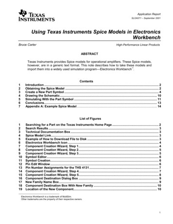
SLOA071Figure 23. Simulation ResultsThis is the result that is expected, although it is not immediately apparent. ElectronicsWorkbench has no command to mathematically add the two outputs, one of which displays inred, and the other in blue. The blue overwrites the red, both of which have an amplitude –6 dB inthe passband. On the phase plot, they are both shown 180 out of phase. Therefore, thedifferential output would have an amplitude of 0 dB in the passband.The Spice model has been successfully translated into an Electronics Workbench simulation.6ConclusionsTexas Instruments Spice models, in their downloaded form, are not directly usable in ElectronicsWorkbench. They can be used successfully, following the procedure given in this note.Using Texas Instruments Spice Models in Electronics Workbench13
SLOA071Appendix A: Example Spice Model* THS4131 SUBCIRCUIT* FULLY DIFFERENTIAL HIGH SPEED MONLITHIC OPERATIONAL AMPLIFIER* WRITTEN 9/18/00* TEMPLATE X @REFDES %IN %IN- %VCC %VCC- %OUT %OUT- %VOCM @MODEL* CONNECTIONS:NON-INVERTING INPUT* INVERTING INPUT* POSITIVE POWER SUPPLY* NEGATIVE POWER SUPPLY* OUTPUT * OUTPUT * VOCM* .SUBCKT THS41311 2 3 4 5 5b 17** INPUT *Q127 1 28 NPN IN 2Q225 2 29 NPN IN 2R226 29 15R126 28 15* SECOND STAGE *Q307 Vref 27 PNP 2Q409 Vref 25 PNP 2Q507 105 06 NPN 1Q709 105 08 NPN 1R34 06 333R44 08 333Cc0 09 25.5pCcb0 07 25.5p* HIGH FREQUENCY SHAPING *Ehf34 0 09 0 1Lhf34 35 7nRhf102 35 25Chf0 102 23pEhfb24 0 07 0 1Lhfb24 33 7nRhfb12 33 25Chfb0 12 23p* OUTPUT *Q8102 102 103 PNP 1Q9102 102 104 NPN 1Q103 103 30 NPN 5Q114 104 31 PNP 7.5R55 30 4R731 5 4Q8b12 12 13 PNP 1Q9b12 12 15 NPN 1Q10b3 13 22 NPN 5Q11b4 15 23 PNP 7.5R5b5b 22 4R7b23 5b 4* Vcm ERROR AMP *Gcm0 105 16 17b 1e-4Vcm17 17b 285e-3Rtop17 3 30k14Using Texas Instruments Spice Models in Electronics Workbench
SLOA071RbotRcmCcmRcm2Ccm217 4 30k16 5 10k16 5b 100p16 5b 10k16 5 100p* BIAS SOURCES *V13 Vref 1.85I13 27 DC 2.1e-3I23 25 DC 2.1e-3I30 103 DC 1.225e-3I426 4 DC 2.1e-3I5104 0 DC 1.86e-3I60 13 DC 1.225e-3I715 0 DC 1.86e-3.MODEL NPN IN NPN IS 170E-18 BF 400 NF 1 VAF 100 IKF 0.0389 ISE 7.6E-18 NE 1.13489 BR 1.11868 NR 1 VAR 4.46837 IKR 8 ISC 8E-15 NC 1.8 RB 25 RE 0.1220 RC 20 CJE 120.2E-15 VJE 1.0888 MJE 0.381406 VJC 0.589703 MJC 0.265838 FC 0.1 CJC 133.8E-15 XTF 272.204 TF 12.13E-12 VTF 10 ITF 0.147 TR 3E-09 XTB 1 XTI 5 KF 7.5E-14.MODEL NPN NPN IS 170E-18 BF 100 NF 1 VAF 100 IKF 0.0389 ISE 7.6E-18 NE 1.13489 BR 1.11868 NR 1 VAR 4.46837 IKR 8 ISC 8E-15 NC 1.8 RB 250 RE 0.1220 RC 200 CJE 120.2E-15 VJE 1.0888 MJE 0.381406 VJC 0.589703 MJC 0.265838 FC 0.1 CJC 133.8E-15 XTF 272.204 TF 12.13E-12 VTF 10 ITF 0.147 TR 3E-09 XTB 1 XTI 5.MODEL PNP PNP IS 296E-18 BF 100 NF 1 VAF 100 IKF 0.021 ISE 494E-18 NE 1.49168 BR 0.491925 NR 1 VAR 2.35634 IKR 8 ISC 8E-15 NC 1.8 RB 250 RE 0.1220 RC 200 CJE 120.2E-15 VJE 0.940007 MJE 0.55 VJC 0.588526 MJC 0.55 FC 0.1 CJC 133.8E-15 XTF 141.135 TF 12.13E-12 VTF 6.82756 ITF 0.267 TR 3E-09 XTB 1 XTI 5.ENDSUsing Texas Instruments Spice Models in Electronics Workbench15
IMPORTANT NOTICETexas Instruments Incorporated and its subsidiaries (TI) reserve the right to make corrections, modifications,enhancements, improvements, and other changes to its products and services at any time and to discontinueany product or service without notice. Customers should obtain the latest relevant information before placingorders and should verify that such information is current and complete. All products are sold subject to TI’s termsand conditions of sale supplied at the time of order acknowledgment.TI warrants performance of its hardware products to the specifications applicable at the time of sale inaccordance with TI’s standard warranty. Testing and other quality control techniques are used to the extent TIdeems necessary to support this warranty. Except where mandated by government requirements, testing of allparameters of each product is not necessarily performed.TI assumes no liability for applications assistance or customer product design. Customers are responsible fortheir products and applications using TI components. To minimize the risks associated with customer productsand applications, customers should provide adequate design and operating safeguards.TI does not warrant or represent that any license, either express or implied, is granted under any TI patent right,copyright, mask work right, or other TI intellectual property right relating to any combination, machine, or processin which TI products or services are used. Information published by TI regarding third–party products or servicesdoes not constitute a license from TI to use such products or services or a warranty or endorsement thereof.Use of such information may require a license from a third party under the patents or other intellectual propertyof the third party, or a license from TI under the patents or other intellectual property of TI.Reproduction of information in TI data books or data sheets is permissible only if reproduction is withoutalteration and is accompanied by all associated warranties, conditions, limitations, and notices. Reproductionof this information with alteration is an unfair and deceptive business practice. TI is not responsible or liable forsuch altered documentation.Resale of TI products or services with statements different from or beyond the parameters stated by TI for thatproduct or service voids all express and any implied warranties for the associated TI product or service andis an unfair and deceptive business practice. TI is not responsible or liable for any such statements.Following are URLs where you can obtain information on other Texas Instruments products & samplifier.ti.comAudiowww.ti.com/audioData andInterfaceinterface.ti.comDigital ilitarywww.ti.com/militaryPower Mgmtpower.ti.comOptical Telephonywww.ti.com/telephonyVideo & Mailing Address:Texas InstrumentsPost Office Box 655303 Dallas, Texas 75265Copyright 2003, Texas Instruments Incorporated
Open the Electronics Workbench Program. Figure 6 shows the Icon: Figure 6. Electronics Workbench Icon When the program opens, a new schematic window is created automatically. The new part symbol editor is available from the schematic entry window. Click, tools, create new component. This opens a dialog box that starts a six-step process of .