Transcription
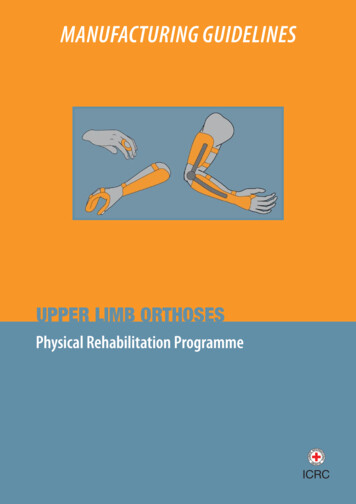
MANUFACTURING GUIDELINESUPPER LIMB ORTHOSESPhysical Rehabilitation Programme
International Committee of the Red Cross19, avenue de la Paix1202 Geneva, SwitzerlandT 41 22 734 60 01 F 41 22 733 20 57Email: shop@icrc.org www.icrc.org ICRC, December 2014All photographs: ICRC/PRP
Table of contentsForeword 2The ICRC polypropylene technology 2Objective of the manuals 3Introduction 4Fundamentals 4Casting and rectification 71. Static interphalangeal splint (Stax finger splint) 82. Static interphalangeal splint (ring splint) 113. Metacarpophalangeal block splint (figure-of-eight splint) 134. Hand-based thumb immobilization splint 155. Wrist immobilization splint 186. Thumb and wrist immobilization splint 247. Hand and wrist immobilization splint 288. Elbow and wrist immobilization orthosis 369. Articulated free-motion elbow orthosis (Tamarack) with wrist support 4210. (Side-bar) hinged free-motion elbow orthosis with wrist support 4411. Overlapping (lockable) articulated elbow orthosis with wrist support 4712. Spiral orthosis 5013. Thoracobrachial orthosis 5414. Wheelchair pushing glove 60Bibliography 63Key 63Manufacturing Guidelines Upper limb orthoses1
ForewordThe ICRC polypropylene technologySince its inception in 1979, the ICRC’s Physical Rehabilitation Programme has developed– and promoted the use of – technology that is suited to the needs of specific contexts in whichthe organization operates, i.e. countries affected by war and low-income or developing countries.The technology must also be adapted to the needs of the physically disabled in the countriesconcerned.Therefore, it must be: durable, comfortable, easy to use and, for the user, easy to maintain as well;easy for professionals to repair;standardized, but compatible with the climate in different regions of the world;affordable, but modern and consistent with internationally accepted standards;readily available.The choice of technology is of great importance for ensuring access to physical rehabilitation servicesand for promoting the sustainability of these services.For all these reasons, the ICRC has chosen to develop its polypropylene technology instead ofbuying ready-made orthopaedic components, which are generally too expensive and unsuited tothe contexts in which the organization works. The cost of the materials used in ICRC prosthetic andorthotic devices is less than that of the materials used in appliances assembled from commercialready-made components.When the ICRC launched its Physical Rehabilitation Programme in 1979, locally available materialssuch as wood, leather and metal were used, and orthopaedic components manufactured locally.In the early 1990s the ICRC began to standardize the techniques used in its various projects aroundthe world; this was done for the sake of uniformity, but an even more important consideration wasimproving the quality of services for people with physical disabilities.Polypropylene was introduced into ICRC projects in 1988, for manufacturing prosthetic sockets.The first polypropylene knee-joint was produced in Cambodia in 1991; other components, such asvarious alignment systems, were first developed in Colombia and gradually improved. In addition,a durable foot, made initially of polypropylene and ethylene vinyl acetate (EVA), and now ofpolypropylene and polyurethane, has replaced the traditional wooden/rubber foot.In 1998, after careful consideration, it was decided to scale down local component productionin order to focus on care for service users and training for personnel at country level.2ICRC Physical Rehabilitation Programme
Objective of the manualsThe ICRC’s Manufacturing Guidelines are designed to provide the information necessary to producehigh-quality assistive devices.The main aims of these informative manuals are as follows: to promote and enhance the standardization of ICRC polypropylene and low-temperaturethermoplastic technologies; to provide support for training in the use of these technologies; to promote good practice.This is another step forward in the effort to ensure that people with physical disabilities have accessto appropriate services of good quality.Physical Rehabilitation ProgrammeHealth UnitAssistance DivisionICRCManufacturing Guidelines Upper limb orthoses3
IntroductionAll orthotics should be prescribed by a doctor. Current upper-limb orthoses (ULO) can be readymade or tailor-made, but both must be fitted to the patient by a professional (if possible, by anorthotist).The aim of this document is to describe methods for manufacturing some of the most widelyused ULO, working with polypropylene and low-temperature thermoplastic technologies. But thepurpose of the document is not to detail all the existing ULO or to specify their positioning, whichvaries according to the pathology presented.FundamentalsThere are several ways of classifying orthoses: ready-made or tailor-made orthoses, depending on how they are manufactured functional/activity orthoses or inactivity orthoses, depending on their use articulated or unarticulated orthoses, depending on their design.But in general, by combining several mechanical principles, orthoses achieve a variety of therapeuticgoals and thus have many indications.Mechanical principlesOne or several principles may be used in the same orthosis.StabilizationStress on the segments is low.MotionlessThe segments are immobilized in a rest position.MobileThe orthosis guides segments in their movements.FreeThe segments can be moved in their full range of motion.With amplitude limitationSegment movements are limited to fixed minimum and maximum amplitudes.PostureConstant directional force is applied to the segments.4ICRC Physical Rehabilitation Programme
StaticStatic and serial staticThe segments are immobilized in a stressed position and the correction is achievedby applying several orthoses (or modifications of the same orthosis), progressivelypositioning the segments in the desired position.Progressive staticThe segments are immobilized in a stressed position and the correction is achievedby using a non-elastic adjustable motor.DynamicWith constant tractionThe force is exerted by an elastic or spring motor; it is constant, regardless of theposition of the segments.DynastaticThe force becomes zero when the segments reach the desired position.CompressiveRigidThe force is continuous and is exercised by a rigid surface.ElasticThe orthosis exerts an elastic stress, adapting to changes in segment volume butpreventing any increase in that volume.Therapeutic goals and indicationsImmobilization- of treatment areasThe orthosis is worn at all times to promote healing (tendon and ligamentinjuries, etc.).Manufacturing Guidelines Upper limb orthoses5
- during rest periodsThe orthosis is worn during periods of inactivity for its analgesic, anti-inflammatoryand protective effects on the joints (rheumatoid arthritis, osteoarthritis, etc.).Where there is constant pain with signs of inflammation, the orthosis immobilizes theaffected joint plus the joint above and/or the joint below, as the case may be. Wherethere is active pain or permanent pain without signs of inflammation, the orthosisimmobilizes only the joint involved.StabilizationFreeThe orthosis stabilizes one or more joints in cases of deformity and improves thegesture (rheumatoid arthritis etc.).With amplitude limitationThe orthosis prevents the joints from reaching painful or unstable amplitude sectors(dislocations etc.).Correction- of range of motion deficit (stiffness)The orthosis positions segments to recover lost range of motion (tendon adhesions,capsular ligament retractions, etc.). The device is of no use in cases of strictly passivelimitation (ankylosis, arthrodesis, etc.).- of deformityThe orthosis positions the segments in the physiological functional position tocombat the deformity.Compensation of a motor deficitThe orthosis positions the segments to compensate the affected muscle groups and avoid muscle powerimbalances leading to deformities and retractions (central and peripheral paralysis, etc.).CompressionRigidBy exerting constant compression on the healing areas, the orthosis reduces theneovascularization that is responsible for hypertrophic scars (burns etc.).ElasticBy exerting variable compression, depending on segment volume, the orthosispromotes the reabsorption of subcutaneous collections of fluid (post-traumatic orvenolymphatic oedema, etc.).Guiding cutaneous healingThe orthosis positions the segments in a position of maximum cutaneous stretch where thereis a retractile scar (burns etc.).6ICRC Physical Rehabilitation Programme
Casting and rectificationPatient assessment, casting and rectification of positive cast impressions are performed inaccordance with prosthetic and orthotic (P&O) standards.Casting includes numerous variables (wrist included or not, angulations of the joints, and so on),depending on the type of orthosis to be created and the indication.RectificationThe correction will free a space in bony areas and areas of nerve vulnerability in the upper limb.Bony areas:EL (Lateral epicondyle), O (olecranon), SU (Ulnar styloid), SR (Radial styloid),MP (Metacarpophalangeal joint), IP (Interphalangeal joint)TS (Scaphoid tubercule), P (Pisiform), SC (Scaphoid), EM (Medial epicondyle).Nerve vulnerability areas:GR (Radial or torsion gutter of the radial nerve), R (Radial nerve), M (Median nerve),U (Ulnar nerve).Manufacturing Guidelines Upper limb orthoses7
1STATIC INTERPHALANGEAL SPLINT (STAX FINGER SPLINT)1.1. Action Stabilization and static posture in extension of thedistal or proximal interphalangeal joint. Immobilization of treatment areas or during restperiods, correction of range of motion deficit ordeformity and compensation of motor deficit (alsostabilization with amplitude limitation). Can be used upside down to produce the oppositeeffect.1.2. Trim line of the splint1.2.1. Static distal interphalangeal splint, Stax finger splintThis orthosis can be adapted to the four distalinterphalangeal joints of the hand.Mark the trim line as follows:A On the dorsum of the finger, the distal edge isproximal to the distal interphalangeal joint.B On the dorsum of the finger, the proximal edgeis distal to the proximal interphalangeal joint.C On the palmar face of the finger, the proximaledge is distal to the distal interphalangeal joint.1.2.2. Static proximal interphalangeal splintThis orthosis can be adapted to the five proximalinterphalangeal joints of the hand.Mark the trim line as follows:A On the dorsum of the finger, the distal edge isproximal to the proximal interphalangeal joint.B On the dorsum of the finger, the proximal edgeis distal to the metacarpophalangeal joint.C On the palmar face of the finger, the distal edgeis proximal to the distal interphalangeal joint,allowing it to flex (except for the thumb).D On the palmar face of the finger, the proximaledge is distal to the proximal interphalangealjoint.8ICRC Physical Rehabilitation Programme
1.3. Creating a paper pattern1.3.1. Static distal interphalangeal splint, Stax finger splintPosition the patient’s hand flat on a sheet of paper with the fingers extended and slightly abducted.Draw the outline of the finger and mark the interphalangeal joints (IPP and IPD).Measure the circumference of the finger at the distal interphalangeal joint and distally to theproximal interphalangeal joint.Draw the pattern as illustrated: At the distal interphalangeal joint (IPD), the widthof the pattern (a) is equal to half the circumferenceof the finger there. Slightly distally to the proximal interphalangealjoint (IPP), the width of the pattern (b) is equal tohalf the circumference of the finger there. Make a slit the width of the finger proximally to thedistal interphalangeal joint (IPD). The pattern should be rounded and must not haveany angles.Cut out the paper pattern and try it on the patient’sfinger; check that the ends match.1.3.2. Static proximal interphalangeal splintPosition the patient’s hand flat on a sheet of paper with the fingers extended and slightly abducted.Draw the outline of the finger and mark the proximal interphalangeal and metacarpophalangeal joints(IPP and MP).Measure the circumference of the finger at the proximal interphalangeal joint and distally to themetacarpophalangeal joint.Draw the pattern as illustrated: At the proximal interphalangeal joint (IPP),the width of the pattern (c) is equal to half thecircumference of the finger there. Slightly distally to the metacarpophalangeal joint(MP), the width of the pattern (d) is equal to halfthe circumference of the finger there. Make a slit the width of the finger proximally to theproximal interphalangeal joint (IPP). The pattern should be rounded and must notinclude angles.Cut out the paper pattern and try it on the patient’sfinger; check that the ends match up.Manufacturing Guidelines Upper limb orthoses9
1.4. Cutting the low-temperature thermoplastic plateDraw the pattern on a low-temperature thermoplasticplate.Heat the plate in a bath at 65 C (C-Lite).Cut the low-temperature thermoplastic plate on asupport so as not to stretch the material.1.5. Moulding the low-temperature thermoplasticPosition the patient’s hand upright with the elbow onthe table, the fingers slightly abducted, and the fingerto be splinted straight.Heat the plate in a bath at 65 C (C-Lite).Insert the patient’s finger into the slit, the rear partbeing dorsal.Mould the thermoplastic, one hand forming the distalpart and the other the proximal part. A twisted creasewill appear on either side; flatten these creases gently.1.6. Preparing the low-temperature thermoplasticshellIf necessary, grind and smooth the trim line.1.7. ClosureStick a Velcro hook 1 cm wide over the entire width ofthe back part of the splint.Cut a Velcro loop strap 1 cm wide and hook it ontothe Velcro hook at both ends.1.8. Initial fitting and finishingIn accordance with international P&O standards, trythe splint on the patient.Modify the shell as required by reheating it locallywith a hot-air gun (nozzle-tipped for greaterprecision), and then grind and smooth the shell.Adjust the Velcro to reduce or limit the flexion of theinterphalangeal joint as required.10ICRC Physical Rehabilitation Programme
2STATIC INTERPHALANGEAL SPLINT (RING SPLINT)2.1. Action Mobile stabilization with extension limitation ofthe proximal or distal interphalangeal joint. Stabilization with amplitude limitation. Can be used upside down to produce the oppositeeffect.2.2. Trim line of the splint2.2.1. Distal interphalangeal ring splintThis orthosis can be adapted to the four distalinterphalangeal joints of the hand.Mark the trim line as follows:A On the dorsum of the finger, the distalpart of the orthosis is distal to the distalinterphalangeal skin folds.B On the dorsum of the finger, the proximalpart of the orthosis is proximal to the distalinterphalangeal skin folds.C On the palmar face of the finger, the orthosisis located on the flexion crease of the distalinterphalangeal joint.2.2.2. Proximal interphalangeal ring splintThis orthosis can be adapted to the five proximalinterphalangeal joints of the hand.Mark the trim line as follows:A On the dorsum of the finger, the distal partof the orthosis is distal to the proximalinterphalangeal skin folds.B On the dorsum of the finger, the proximal partof the orthosis is proximal to the proximalinterphalangeal skin folds.C On the palmar face of the finger, the orthosisis located on the flexion crease of the proximalinterphalangeal joint.Manufacturing Guidelines Upper limb orthoses11
2.3. Measuring and cutting the low-temperature thermoplastic plateMeasure the length of the figure-of-eight splint path using a tape: From the flexion crease on the palmar side of the finger, pass distal to the interphalangeal skinfolds on the dorsum of the finger. Go around the finger to return to the flexion crease. Pass proximal to the interphalangeal skin folds of the dorsum of the finger and return to theflexion crease.Cut a strip of thermoplastic 7 to 10 mm wide and the length of the splint path.2.4. Moulding the low-temperature thermoplasticPosition the patient’s hand upright with the elbow onthe table, the fingers slightly abducted, and the fingerto be splinted slightly flexed.Heat the plate in a bath at 65 C (C-Lite).Mould the thermoplastic describing the samefigure-of-eight path as for the measuring.2.5. Preparing the low-temperature thermoplasticshellIf necessary, grind and smooth the trim line.2.6. Initial fitting and finishingIn accordance with international P&O standards, trythe splint on the patient.12ICRC Physical Rehabilitation Programme
3METACARPOPHALANGEAL BLOCK SPLINT (FIGURE-OF-EIGHT SPLINT)3.1. Action Mobile stabilization with extension limitationof the metacarpophalangeal joints of the fingers(or only of the 4th and 5th), usually at 30-45 offlexion. Treatment, stabilization with amplitude limitationand compensation of motor deficit.3.2. Trim line of the splintMark the trim line as follows:A On the dorsum of the hand, the distal part ofthe splint is distal to the metacarpophalangealskin folds, bearing on the first phalanges.B On the dorsum of the hand, the proximal partof the splint is proximal to the metacarpophalangeal skin folds, bearing on themetacarpals.C On the palmar face of the hand, the orthosis islocated on the metacarpal heads.Note that the distal dorsal part must cover onlythe 4th and 5th finger (ulnar or medio-ulnar nervepalsy), passing between the 3rd and 4th finger to jointhe palmar part.Manufacturing Guidelines Upper limb orthoses13
3.3. Measuring and cutting the low-temperature thermoplastic plateMeasure the figure-of-eight splint using a tape: Starting from the 5th metacarpal head on the palmar side of the hand, pass proximal to themetacarpophalangeal skin folds on the dorsum of the hand. Go through the 1st commissure to return to the 5th metacarpal head. Pass distal to the metacarpophalangeal skin folds on the dorsum of the hand and go throughthe 1st commissure (or between the 3rd and 4th finger if ulnar nerve palsy) to reach the 5thmetacarpal head.Cut a strip of thermoplastic 20 mm wide and the length of the splint path.3.4. Moulding the low-temperature thermoplasticPosition the patient’s hand upright with the elbow onthe table and the fingers slightly abducted and flexedin the desired position.Heat the plate in a bath at 65 C (C-Lite).Mould the thermoplastic describing the samefigure-of-eight as for the measuring.3.5. Preparing the low-temperature thermoplastic shellIf necessary, grind and smooth the trim line.3.6. Initial fitting and finishingIn accordance with international P&O standards, trythe splint on the patient.14ICRC Physical Rehabilitation Programme
4HAND-BASED THUMB IMMOBILIZATION SPLINT4.1. Action Motionless stabilization and static posture of thetrapeziometacarpal, metacarpophalangeal andinterphalangeal joints (if included in the orthosis)of the thumb. Immobilization of treatment areas or during restperiods, correction of range of motion deficit ordeformity and compensation of motor deficit.4.2.Trim line of the splintMark the trim line as follows:A On the dorsum of the hand, the distal edge isproximal to the metacarpal heads.B On the dorsum of the hand, the proximal edgeis distal to the ulnar styloid.C At the thumb trough, the distal edge isproximal to the interphalangeal joint, if ithas to be left free, or distal, if it has to beimmobilized.D On the palmar face of the hand, the distaledge of the C-bar is proximal to the proximalpalmar crease, allowing free flexion of the 2ndfinger.E On the palmar face of the hand, the medialedge of the thumb trough includes the thenarcrease to secure the thumb and stops distally tothe distal wrist crease in order not to interferewith wrist motion.F On the palmar face of the hand, the proximaledge stays distal to the distal wrist crease inorder not to interfere with wrist motion.G On the palmar face of the hand, the distaledge of the ulnar part is proximal to the distalpalmar crease to allow flexion of the 5th finger.Manufacturing Guidelines Upper limb orthoses15
4.3. Creating a paper patternPosition the patient’s hand flat on a sheet of paper with the fingers extended and slightly abducted.Draw the outline of the hand and mark the metacarpal heads of the 2nd and 5th finger, the ulnarstyloid (SU) and the metacarpophalangeal joint of the thumb (MP).Measure the circumference of the wrist.Draw the pattern as illustrated: Draw the proximal edge of the pattern distally tothe ulnar styloid, centred on the wrist, its widthequal to half the circumference of the wrist (e). Draw the ulnar edge of the pattern, at the samedistance from the outline of the hand, and stopproximally to the head of the 5th metacarpal (M V). Draw the distal edge of the pattern with a straightline proximal to the 5th and 2nd metacarpal headsand twice the width of the hand (g). Draw the radial edge of the pattern, firstreaching a point (Y) 7-8 cm (f) outside themetacarpophalangeal joint of the thumb (MP)and then connecting with the proximal edge ofdeparture. The pattern should be rounded and must not haveany angles.Cut out the paper pattern and try it on the patient’shand; check that the ends match up, especially around the thumb.4.4. Cutting the low-temperature thermoplastic plateFollow the procedure for cutting the low-temperature thermoplastic plate described in section 1.4.4.5. Moulding the low-temperature thermoplasticPosition the patient’s hand upright with the elbow on the table, the fingers slightly abducted and thethumb in the desired position of immobilization (in the case of palmar abduction, make the tip of thethumb touch the 2nd and 3rd fingers).Heat the plate in a bath at 65 C (C-Lite).16ICRC Physical Rehabilitation Programme
Mould the thermoplastic: The radial part of the pattern wraps around thethumb and goes through the first web space to bewelded to the dorsal side of the splint. The ulnar part wraps around the hypothenareminence. Flare the proximal edge at the wrist. Roll the distal edge of the thumb trough back tofree the interphalangeal joint if it has to be left free.4.6. Preparing the low-temperature thermoplastic shellIf necessary, grind and smooth the trim line.4.7. ClosureGlue a Velcro hook 3 cm wide to the palmar surface of the thumb trough (the edges can be embeddedin the plastic with a soldering iron).Hook a Velcro loop strap onto the thumb trough, mark its position on the palmar face of the ulnar part,and fix it by embedding it in the plastic, which has been preheated with a hot-air gun (or by sticking aVelcro hook 3 cm wide to the ulnar part).4.8. Initial fitting and finishingIn accordance with international P&O standards, trythe splint on the patient.Modify the shell as required by reheating it locally witha hot-air gun (nozzle-tipped for greater precision), andthen grind and smooth it.Manufacturing Guidelines Upper limb orthoses17
5WRIST IMMOBILIZATION SPLINT5.1. Action Motionless stabilization and static posture of thewrist, splint with palmar, dorsal or ulnar shell. Immobilization of treatment areas or during restperiods, correction of range of motion deficit andcompensation of motor deficit. Immobilization in maximum extension or flexionof the wrist is avoided (except for amplituderecovery) since it can cause carpal tunnelsyndrome.5.2. Trim line of the splintMark the trim line as follows:A The proximal edge is located at the proximalthird of the forearm.B On the palmar face of the hand, the distal edgeis proximal to the distal palmar crease fromthe 5th to the 3rd finger and proximal to theproximal palmar crease at the 2nd finger (forpalmar creases see section 4.2).C At the thumb, the edge leaves the thenareminence free and follows the thenar crease onthe palmar face.D On the dorsum of the hand, the distal edge isproximal to the metacarpal heads.If the splint is made of polypropylene, continuewith section 5.3; if it is made of low-temperaturethermoplastic, skip to section 5.4.18ICRC Physical Rehabilitation ProgrammePP
5.3. Polypropylene splint5.3.1. The EVA layer5.3.1.1. Purpose of the EVA layerThe EVA layer (6 mm) can be moulded beforethe polypropylene is draped, for the followingpurposes: To improve comfort. To prevent skin breakage in patients withsensation loss. For orthoses used at night.If EVA is not required, go directly to the section onvacuum-moulding the polypropylene.5.3.1.2. Moulding the EVA layerPosition the plaster model with the palm facing up.Measurements of the sheet of EVA: Width Length Thickness circumference of the elbow length of the plaster model(forearm hand) 6 mmHeat the EVA at 120 for 3 to 5 minutes.Drape the EVA manually over the plaster model and hold it in place until completely cool.Cut off the surplus.Staple the EVA onto the dorsal face of the plaster model.Manufacturing Guidelines Upper limb orthoses19
5.3.2.Vacuum-moulding the polypropylenePull a stocking over the plaster model.Dust the stocking with talcum powder.Measurements of the sheet of polypropylene:1 Circumference of the elbow 10 cm.2 Circumference of the hand 10 cm.3 Length of the plaster model (forearm hand) 10 cm.Thickness 3 or 4 mm, depending on the patient’ssize.Heat the polypropylene at 180 for 20 to 35 minutes,depending on the thickness of the material and theefficiency of the oven.Drape the polypropylene over the plaster model andstick it together along the dorsal face.Using a cord or band, tighten the polypropylenearound the suction cone.Open the vacuum valve.Cut off the surplus plastic while it is still hot.Keep the vacuum on until the polypropylene cools.5.3.3. Preparing the polypropylene shellDraw the trim line on the plastic as described insection 5.2.Following the outline, cut out the orthosis with anoscillating saw.Remove the plastic shell from the plaster model andthe stocking from inside the shell.Grind and smooth the trim line.If an EVA layer has been moulded, transfer the trimline to the EVA and cut off the surplus.Then go to section 5.5.20ICRC Physical Rehabilitation Programme
5.4. Low-temperature thermoplastic splint5.4.1. Creating a paper patternPosition the patient’s hand and forearm flat on asheet of paper with the fingers extended and slightlyabducted.Draw the outline of the hand and forearm, mark themetacarpal heads of the 2nd (M II) and 5th (M V)fingers and the proximal third of the forearm (1/3 AB).Measure the circumference of the wrist and of theforearm (at its proximal third).Draw the pattern as illustrated: At the proximal third of the forearm, draw theproximal edge of the pattern, centred on theforearm, its width equal to half of the circumferenceat this point (h). Draw the ulnar and radial edges in a straight lineto the wrist, where the pattern is centred, its widthequal to half the circumference of the wrist (e). Continue the ulnar and radial edges on eitherside of the palm at a distance of 3 cm (i) from theoutline of the hand. Draw the distal edge of the pattern proximal to themetacarpal heads (M II and M V). Make a hole 3 cm in diameter, its border about 3 cmfrom the distal edge and 3 cm from the radial edgeof the pattern. The pattern should be rounded and must not haveany angles.Cut out the paper pattern and try it on the patient’shand; check that the ends match up, especially aroundthe thumb.5.4.2. Cutting the low-temperature thermoplastic plateFollow the procedure for cutting the low-temperature thermoplastic plate described in section 1.4.Manufacturing Guidelines Upper limb orthoses21
5.4.3. Moulding the low-temperature thermoplasticPosition the patient’s forearm on its dorsum, the wristresting on a roll (rolled towel) and in the desiredposition of immobilization. The fingers should beslightly abducted and the thumb should touch the 2ndfinger to preserve the physiological arches of the hand.Heat the plate in a bath at 65 C (C-Lite).Slip the patient’s thumb into the hole in the plate. Mould the thermoplastic around the forearm andhand. Roll the plastic around the thenar eminence backto allow free motion of the thumb. Roll the plastic of the distal edge back to allowmotion of the fingers. Flare the proximal edge.5.4.4. Preparing the low-temperature thermoplastic shellIf necessary, grind and smooth the trim line.5.5. Making the straps5.5.1. Simple strapThis is preferred for low-temperature plastic orthotics and for closing small gaps as with patients ofsmall size. Stick a Velcro hook onto the splint surface on both sides of the area to be closed (the edges can beembedded in the plastic with a soldering iron). Hook the ends of a Velcro loop strap onto the Velcro hooks (one end of the Velcro loop strap canalso be fixed to the plastic with a tubular rivet).5.5.2. Strap with loopThis is preferred for polypropylene orthotics and when closure needs to be resistant. Sewn straps fitbetter and are more comfortable than the prefabricated ones. Fix the loop to the plastic orthosis (usually on the outside) with a tubular rivet; it should not be incontact with the patient’s skin. Adjust the length of the straps once they have been fixed to the loop and, if possible, adjust againduring the fitting. Fix the strap after making sure it is perpendicular to the general axis of the orthosis. Cover the surface of the strap in contact with the patient’s skin with 3 mm EVA.22ICRC Physical Rehabilitation Programme
5.5.3. Positioning the straps One forearm strap fixed 10 mm from the proximaledge One wrist strap One hand strap fixed 10 mm from the distal edge5.6. Initial fitting and finishingIf EVA foam is used, glue it temporarily to the inside of the orthosis.Perform the initial fitting in accordance with P&O standards.Modify the plastic as required and smooth the trim line.If the inside is lined with EVA foam, glue it throughout, cut off the surplus and smooth the trim line.Manufa
gesture (rheumatoid arthritis etc.). With amplitude limitation The orthosis prevents the joints from reaching painful or unstable amplitude sectors (dislocations etc.). Correction - of range of motion deficit (stiffness) The orthosis positions segments to recover lost range of motion (tendon adhesions, capsular ligament retractions, etc.).