Transcription
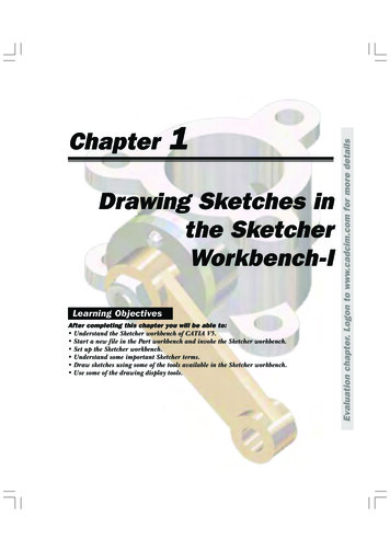
1Drawing Sketches inthe SketcherWorkbench-ILearning ObjectivesAfter completing this chapter you will be able to: Understand the Sketcher workbench of CATIA V5. Start a new file in the Part workbench and invoke the Sketcher workbench. Set up the Sketcher workbench. Understand some important Sketcher terms. Draw sketches using some of the tools available in the Sketcher workbench. Use some of the drawing display tools.Evaluation chapter. Logon to www.cadcim.com for more detailsChapter
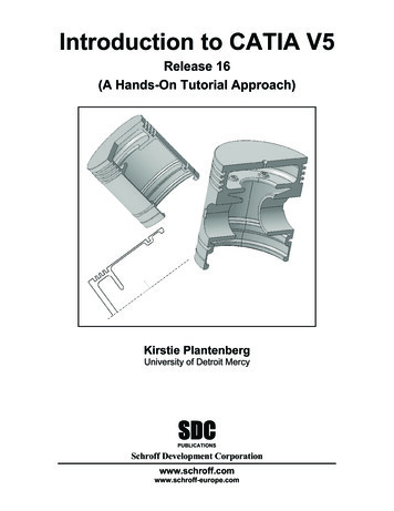
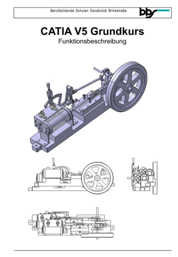
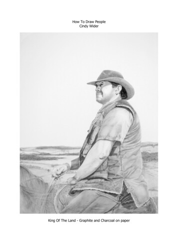
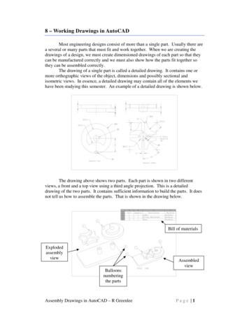
1-2CATIA for Designers (Evaluation Chapter F007/004)Evaluation chapter. Logon to www.cadcim.com for more detailsTHE SKETCHER WORKBENCHMost of the components designed using CATIA are a combination of sketched features, placedfeatures, and derived features. The placed features are created without drawing a sketch,whereas the sketched features require a sketch that defines the shape of the sketched feature.Generally, the base feature of any design is a sketched feature. For example, refer to the solidmodel of the Link shown in Figure 1-1. The base sketch to create this solid model is shown inFigure 1-2.Figure 1-1 Solid Model of a Link.Figure 1-2 Base sketch for the solid model.The Sketcher workbench provides the space and tools to draw sketches of the solid model.Generally, the first sketch that you draw to start the design is called the base sketch, whichcan be converted into a base feature. However, once conversant with the advanced options ofCATIA, you can also use derived feature or a derived part as the base feature. In this chapter,you will learn more about the sketching tools that are available for drawing and displayingthe sketches in the Sketcher workbench.To draw a sketch, you need to invoke the Sketcher workbench in the Part Design workbench orin the Assembly Design workbench. To invoke the Sketcher workbench, choose the Sketchbutton from the Sketcher toolbar and then select a plane on which you need to draw thesketch. After drawing the sketch in this environment, proceed to the Part Design or theWireframe and Surface Design workbench to convert the sketch into a solid model or asurface model.STARTING A NEW FILEWhen you start CATIA V5R13, a new Product file with the name Product1 is displayed onthe screen, as shown in Figure 1-3. Close the Product1 file and start a new file in the PartDesign workbench. You will learn more about the Product files in the later chapters. Afterchoosing Close from File menu, the start screen of CATIA V5 is displayed. Choose Start Mechanical Design Part Design to make sure that you are in the Part Design workbench.Now, to start a new file in the Part Design workbench, choose File from the menu bar. TheNew dialog box is displayed, as shown in Figure 1-4. Select Part from the List of Types list
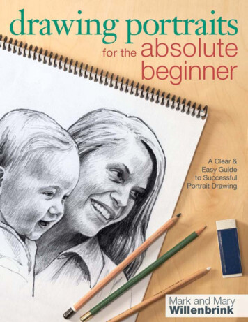
1-3Figure 1-3 Initial screen that appears after starting CATIA V5R13box provided in the New dialog box. You can also write word Part in the Selection edit boxavailable at the bottom of the List of Types list box. Choose the OK button.Figure 1-4 The New dialog boxA new file in the Part Design workbench will be displayed on the screen, as shown in Figure 1-5.The various standard tools like Specification Tree, Compass, Geometry Axis will help youin completing the design. The Specification Tree is displayed on the top left corner of thescreen. The Compass is displayed on the top right corner while the Geometry Axis isdisplayed on the bottom right corner of the screen.Evaluation chapter. Logon to www.cadcim.com for more detailsDrawing Sketches in the Sketcher Workbench-I
Evaluation chapter. Logon to www.cadcim.com for more details1-4CATIA for Designers (Evaluation Chapter F007/004)Figure 1-5 A new Part Design workbench fileNoteYou can hide the Compass, Specification Tree, or the Geometry Axis by using the Viewmenu. By default, check marks are displayed on the left of Geometry, Specifications, andCompass in the menu bar, suggesting that their display is turned on. Choose these optionsagain to turn off their display. The display of these tools should be turned off only when thegeometry area is too small to view the model, else it is recommended not to hide these standardtools.You can also use the F3 key from the keyboard to toggle the display of Specification Tree.INVOKING THE SKETCHER WORKBENCHThe sketch is the basic requirement to create the base feature of any solid model. In CATIA,a sketch is drawn in the Sketcher workbench. To invoke the Sketcher workbench, choose thedown arrow available on the right of the Sketcher button in the Sketcher toolbar; a flyoutappears. Press and hold the left mouse button on the vertical/horizontal line available at theleft/top of the flyout and drag it. The flyout is now detached from its parent toolbar andbecomes an independent toolbar. Figure 1-6 shows the Sketcher flyout as an independenttoolbar. The two buttons that are available with the Sketcher toolbar are Sketcher and Sketchwith Absolute Axis definition. The next section focuses on invoking the Sketcherworkbench using these two buttons.
1-5Figure 1-6 The Sketcher toolbarInvoking the Sketcher Workbench using the Sketcher ButtonTo invoke the Sketcher workbench using the Sketcher tool, choose the Sketcherbutton from the Sketcher toolbar. You are prompted to select a plane, planar face, ora sketch. Select a plane from the three default planes that are available in theSpecification Tree or from the geometry area. The Sketcher workbench, that appears afteryou select the YZ plane as the sketching plane, is shown in Figure 1-7. The selected plane willbe parallel to the screen and you are prompted to select an object or a command. The sketchingcomponents that are displayed in the geometry area are discussed later in this chapter.Figure 1-7 Sketcher workbench invoked using the YZ plane as the sketching planeEvaluation chapter. Logon to www.cadcim.com for more detailsDrawing Sketches in the Sketcher Workbench-I
1-6CATIA for Designers (Evaluation Chapter F007/004)NoteRemember that whenever you invoke the Sketcher workbench, you are always into the Selectmode and are prompted to select an object or a command.Evaluation chapter. Logon to www.cadcim.com for more detailsTo exit the sketcher workbench, choose the Exit workbench button from the Workbench toolbar.Invoking the Sketcher Workbench using the Sketch withAbsolute Axis Definition ButtonIn CATIA, you can also define a user-defined absolute axis while invoking the Sketcherworkbench. This is done using the Sketch with Absolute Axis definition option. To invokethe Sketcher workbench using this option, choose the Sketch with Absolute Axis definitionbutton from the Sketcher toolbar. The Sketch Positioning dialog box appears, as shown in Figure 1-8.You are then prompted to select a plane, two lines, an axis system, a planar face, or a sketch. You canset the absolute axis by using the options available in this dialog box.Figure 1-8 The Sketch Positioning dialog boxSETTING UP THE SKETCHER WORKBENCHAfter invoking the Sketcher workbench, you need to set the workbench as per thesketching or drawing requirements. These requirements include modifying units, grid settings,and so on. The next section focuses on setting these parameters.Modifying UnitsTo modify units, invoke the Options dialog box by choosing Tools Options from the menubar. Click on the sign located on the left of the General option to expand the tree. Choosethe Parameters and Measure option; tabs corresponding to this selection will appear on theright side of the Options dialog box. Now, choose the Units tab. The Options dialog boxafter invoking the Units tab is shown in Figure 1-9.
1-7Figure 1-9 Options dialog box with the Units tab selectedUsing the options available in the Units area, you can set the units for length, angle, time,mass, and so on. After setting units, choose the OK button from the Options dialog box.Modifying the Grid SettingsOn invoking the Sketcher workbench, you will observe two types of lines in the geometryarea, flowing in the horizontal and vertical directions. These are continuous and dotted blacklines. The spacing between two dotted lines is called Graduation, while the spacing betweentwo continuous black lines is called Primary Spacing. The mesh that is formed because ofthe intersection of these lines in vertical and horizontal direction is called Grid. In otherwords, Primary Spacing and Graduation define the Grid.By default, the Graduations is set to 10 in both horizontal and vertical direction. The defaultPrimary Spacing value is 100mm. Though you can change the Primary Spacing andGraduation value in horizontal and vertical direction individually, yet it is recommendednot to change these values. If the values of Primary Spacing or Graduations in horizontalare different than those in the vertical direction, then the Grid is said to be distorted. Tochange the values of Primary Spacing and Graduations, choose Tools Options from themenu bar; the Options dialog box will be displayed. Choose the Mechanical Design optionfrom the tree on the left side of the dialog box. Choose the Sketcher option to display theSketcher tab on the right side of the Options dialog box, as shown in Figure 1-10.The edit boxes of Primary Spacing and Graduations under H row are already enabled.Evaluation chapter. Logon to www.cadcim.com for more detailsDrawing Sketches in the Sketcher Workbench-I
Evaluation chapter. Logon to www.cadcim.com for more details1-8CATIA for Designers (Evaluation Chapter F007/004)Figure 1-10 Options dialog box with the Sketcher option selectedHere, H means the horizontal direction. To enable the edit boxes of Primary Spacing andGraduations under V row, select the Allow Distortions check box. Here, V means verticaldirection. Next, enter the values in the edit boxes corresponding to the H and V directions.Choose OK to apply the newly formed Grid to the Sketcher workbench. Note, all the filesthat you open or start in the Sketcher workbench, henceforth, will use these values for theGrid.UNDERSTANDING THE SKETCHER TERMSBefore learning about the sketching tools, it is important for you to understand some of theterms that are used in the Sketcher workbench. These terms are discussed in the followingsection.Specification TreeThe Specification Tree is a manager, which keeps a track of all the operations that areperformed on the model. When you invoke the Sketcher workbench, a new member or branch,Sketch.1, is added to the Tree. Click on the sign on the right of the PartBody to expand it.Now, you can view the Sketch.1 member of the Specification Tree. A sign is associatedwith the Sketch.1 on the branch. Click on this sign once to further expand the branch.Figure 1-11 shows the Tree in expanded form.The various levels under Sketch.1 in the Tree are discussed next.
1-9Figure 1-11 The expanded form of the Specification TreeTip. While expanding the branch of the Specification Tree, you mayaccidentally click on the branch lines. This will make the Specification Treeactive and consequently the geometry area will be frozen. Note, that the color of thedefault planes will turn grey. Now, zooming and panning will respectively resizeor reposition the Specification Tree, instead of the geometry view. Thegeometry area can be reactivated by clicking on the branch line again.AbsoluteAxisIn Sketcher workbench, the default horizontal and vertical axes passing from the origin (0,0), toinfinity are referred to as AbsoluteAxis. The horizontal and vertical axis in the geometryarea will be highlighted, when the AbsoluteAxis is selected from the Specification Tree . A sign is available on the left of the AbsoluteAxis in the Specification Tree. Click this signonce to expand one down level of the branch. The levels associated with this branch arediscussed below.OriginThe Origin in Sketcher workbench is the point where the absolute horizontal axisintersects the absolute vertical axis. The coordinates for origin are (0,0). Origin is widelyused while applying dimensional constraints to the sketches. You will learn more aboutdimensional constraints in the later chapters.HDirectionThe direction that is parallel to the horizontal axis is referred to as horizontal direction.The HDirection is mostly used to constrain a sketch.VDirectionThe direction that is parallel to the vertical axis is referred to as vertical direction. TheVDirection is mostly used to constrain a sketch.The branches in the Specification Tree will increase as the design process continues. Whiledrawing and constraining sketches, you will learn more about the branches that areassociated with the Specification Tree in Sketcher workbench.Evaluation chapter. Logon to www.cadcim.com for more detailsDrawing Sketches in the Sketcher Workbench-I
1-10CATIA for Designers (Evaluation Chapter F007/004)Snap to PointEvaluation chapter. Logon to www.cadcim.com for more detailsThis option is used to snap to the point of intersection of the Primary Spacing andthe Graduation lines while sketching. By default, the snap mode is active. To activateor deactivate the snap mode, choose the Snap to Point button from the Sketch toolstoolbar, which appears only when you invoke the Sketcher workbench.Construction/Standard ElementAn element that is not a part of the profile while creating features and is used only asa reference or to constrain the elements of the sketch in the Sketcher workbench iscalled a Construction element. The construction elements can be used only in theSketcher workbench. A Standard element is the one that takes part in the featurescreation. Depending on the requirement of the design, you can convert a standard elementto a construction element or vice a versa using the Construction/Standard Element button.Sketcher ToolbarWhile drawing a sketch, you often need to select some elements. The tools that are requiredto perform such a job are available in the Sketcher toolbar, shown in Figure 1-12. Varioustools such as Select, Selection Trap, and so on are available in this toolbar. By default, theSelect tool is activated in the sketcher workbench, unless any other tool or an object is selected.Figure 1-12 The Sketcher toolbarThe tools available with Sketcher toolbar can be invoked by choosing the down arrowavailable on the right of the Select tool. When you choose the down arrow, the Select flyoutis displayed. Detach the Select flyout from the Sketcher toolbar by holding it from the vertical/horizontal line and place it in the geometry area. The Select flyout will now become Selecttoolbar, as shown in Figure 1-13 . The tools available in Select toolbar are discussed in thefollowing section.Figure 1-13 The Select toolbarNoteFor a better understanding and explanation of the buttons available in the flyout, this book willrefer a flyout as a toolbar. This means, whenever you are asked to choose the down arrowavailable on the right of any button, the flyout that appears, will be called a toolbar. You candetach this flyout from the parent toolbar and place it in the geometry area.
Drawing Sketches in the Sketcher Workbench-I1-11SelectSelection TrapThis is a method of selecting elements by creating a selection trap, which is arectangular box drawn by dragging the mouse to define the diagonally oppositecorners. All the objects that lie fully inside the selection trap are selected. To createthis trap, choose the Selection Trap button from the Select toolbar. Now, specify the firstcorner and then drag the mouse to specify the second corner.Intersecting TrapAn intersecting trap is similar to the selection trap, with the only difference that thismethod allows you to select elements of a sketch that are inside or are intersected bythe trap. To create it, choose the Intersecting Trap button from the Select toolbar.Now specify the first corner and then drag the mouse to specify the second corner.Polygon TrapThis method includes selecting elements by drawing a closed polygon as the selection trap.You can select elements of a sketch that are fully inside the polygon by using this method.Choose the Polygon Trap button from the Select toolbar and draw a closed polygon byspecifying its adjacent corners. Polygon creation can be terminated by double-clicking.Paint Stroke SelectionThis method includes selecting elements by dragging the mouse to draw a paintstroke across them. The elements that are intersected by the paint stroke are selected.Outside Trap SelectionThe elements that are outside the selection trap are selected by using this method.The elements that are intersected by the trap are not selected.Intersecting Outside Trap SelectionThe elements that are outside the selection trap or are intersected by the selectiontrap are selected by using this method.Inferencing LinesThe inferencing lines are temporary lines that are used to track a particular point on thescreen. They are automatically displayed from the endpoints of the sketched elements orfrom the origin when you select a sketching tool in the sketcher environment. Consider acase in which you want to draw a line, such that its end point is tangent to the circle. Specifythe start point of the line and then move the cursor in the direction tangent to the circle. Youwill note that the inference line is shown tangent to the existing circle. Now, specify theendpoint of the line. Figure 1-14 shows the use of the inferencing line to draw a line whoseend point is tangent to an existing circle.Evaluation chapter. Logon to www.cadcim.com for more detailsThis tool allows you to make selection of the elements. As you move the arrow cursornear the element with Select tool activated, the arrow cursor is replaced with a handcursor. Left click on the element to select.
Evaluation chapter. Logon to www.cadcim.com for more details1-12CATIA for Designers (Evaluation Chapter F007/004)Figure 1-14 An example of inferencing lineDRAWING SKETCHES USING THE SKETCHER TOOLSThe sketching tools that are used to draw the sketches in the Sketcher workbench arediscussed in the following section.Drawing LinesMenu:Toolbar:Insert Profile Line LineProfile LineThe lines are one of the basic sketching tools available in the Sketcher workbench.The general definition of a line is the shortest distance between two points. BecauseCATIA is parametric in nature, it allows the user to draw a line of any length and atany angle, and then change it to the desired length and angle. To draw a line, choose theLine button from the Profile toolbar. There are two methods to draw a line, in CATIA V5.These methods are discussed next in the following section.Drawing Lines by Specifying Points in the Geometry AreaTo draw a line by specifying points in the geometry area, invoke the Line tool by choosing theLine button from the Profile toolbar. You will observe that as you move the cursor in thegeometry area, the coordinates corresponding to the current location of the cursor aredisplayed above it.After invoking the Line tool, you are prompted to select a point or click to locate the startpoint of the line. The prompt sequence is displayed in the Current Information or DialogBox area of the Status bar available below the geometry area. Click anywhere in the geometryarea to specify the start point of the line. You are then prompted to specify its endpoint.Move the cursor away from the start point to specify the endpoint of the line. On movingfrom the start point, you will notice a rubber band line is attached to the cursor. Now, click
Drawing Sketches in the Sketcher Workbench-I1-13Figure 1-15 Line drawn by selecting the start andendpoints from the geometry areaNoteA line in CATIA V5 consists of three geometric elements, the start point, the line segment, andthe endpoint. The start and endpoint are construction elements, while the line segment is standardelement.Drawing Lines Using the Sketch tools ToolbarLines can also be drawn using the Sketch tools toolbar, which is expanded when you invokethe Line tool. Figure 1-16 shows the expanded Sketch tools toolbar, after you invoke theLine tool. There are two methods to draw a line using the Sketch tools toolbar. Thesemethods are discussed next.Figure 1-16 Expanded form of the Sketch tools toolbar after invoking the Line toolDrawing Lines by entering the Start and End point valuesTo draw a line using the start and endpoint values, invoke the Line tool. The Sketchtools toolbar will expand. In the Start Point H and V edit boxes, specify the horizontaland vertical coordinates values of the start point, respectively, and then press ENTERfrom the keyboard. You are then prompted to enter the coordinates values for the endpoint.Specify the values in the End Point H and V edit boxes and press ENTER again. A line isdrawn in the geometry area corresponding to the entered values of the start andendpoints and these dimensions of the start and endpoints are displayed from the origin.Evaluation chapter. Logon to www.cadcim.com for more detailsanywhere in the geometry area to specify the endpoint of the line. Figure 1-15 shows a linedrawn by selecting the points from the display area. The orange color of the line specifies thatit is selected. Click anywhere on the screen to end the selection mode. You will notice that thecolor of the line is changed to white, which suggests that it is a standard element.
1-14CATIA for Designers (Evaluation Chapter F007/004)Evaluation chapter. Logon to www.cadcim.com for more detailsYou will also observe that the Sketch tools toolbar is compressed to its original size afterthe line is drawn. The color of the line created is orange, suggesting it is selected. To endthe selection mode click anywhere in the geometry area. The line will appear green incolor, which means that the line is fully constrained. You will learn more on constraints inlater chapters.Similarly, you can draw a line by specifying the start point and entering the length andangle values.NoteThe dimension values for the start and endpoint that you have entered are displayed, becausethe Dimensional Constraint button is chosen in the Sketch tools toolbar. Let these valuesremain in the geometry area.You will also notice that the color of construction elements such as the start and endpoints of theline is green. This suggests that element is fully constrained. You will learn more aboutdimensioning and constraining of sketches, in later chapters.Drawing Lines with Symmetrical ExtensionTo draw a line with symmetrical extension, invoke the Line tool and choose theSymmetrical Extension button from the expanded Sketch tools toolbar. Whenyou draw the line using this option, its total length is double the distance youmoved, while specifying the start point and the endpoint.In CATIA, few more types of lines such as, infinite line, bisecting line, and bi-tangentline can be drawn. To draw these lines, choose on the down arrow available on the rightof Line button from the Profile toolbar. The Line toolbar will appear, as shown inFigure 1-17. The types of lines that can be drawn using the Line toolbar arediscussed next.Figure 1-17 The Line toolbarDrawing Infinite LinesMenu:Toolbar:Insert Profile Line Infinite LineProfile Line Infinite LineTo draw an infinite line, invoke the Infinite Line tool from the Line toolbar. The Sketchtools toolbar is expanded. You can draw horizontal infinite line, vertical infinite line,and infinite line through two points using the options available in this toolbar.
Drawing Sketches in the Sketcher Workbench-I1-15Drawing Bi-Tangent LinesInsert Profile Line Bi-Tangent LineProfile Line Bi-Tangent LineBi-Tangent lines are the lines that are tangent to two circles, arcs, ellipses, conics, orany curved geometry. You will learn more about these curved geometries later inthis chapter. To draw a bi-tangent line, invoke the Bi-Tangent Line tool from theLine toolbar. Select the first element or the first curve geometry and then select thesecond element. A line will be drawn between the two selected curved elements. You willnotice that tangency symbol is visible on the endpoints of the bi-tangent line. These are thetangent constraints. You will learn more on the tangent constraints in later chapters.Drawing Bisecting LinesMenu:Toolbar:Insert Profile Line Bisecting LineProfile Line Bisecting LineBisecting lines are the lines that pass through two intersecting lines such that theangle formed between them is divided equally. To draw a bisecting line, invoke theBisecting Line tool from the Line toolbar. Select the first line and then select thesecond line. A bisecting line of infinite length is drawn.Drawing Line Normal To CurveMenu:Toolbar:Insert Profile Line Line Normal To CurveProfile Line Line Normal To CurveTo draw a line normal to a curve, choose the Line Normal To Curve button from theLine toolbar. Specify the start point of the line anywhere in the geometry area; youare prompted to select the curve. After you select the curve, a line normal to theselected curve is drawn.Tip. You can use the ESC key from the keyboard to exit a tool, which is currentlyactive.Drawing Center LinesMenu:Toolbar:Insert Profile AxisProfile AxisYou can draw a center line in CATIA using the Axis tool. Generally, the axis tool isused to create the axis for the revolved feature. You will learn more about therevolved features in the later chapters. To draw an axis, invoke the Axis tool fromthe Profile toolbar. The Sketch tools toolbar is expanded and you are prompted tospecify the start point of the axis. Click in the geometry area to specify the start point. YouEvaluation chapter. Logon to www.cadcim.com for more detailsMenu:Toolbar:
Evaluation chapter. Logon to www.cadcim.com for more details1-16CATIA for Designers (Evaluation Chapter F007/004)are then prompted to specify the endpointof the axis. Move the cursor and click tospecify the endpoint of the axis. An axis withthe specified points is displayed in thegeometry area, as shown in Figure 1-18. Youcan also draw an axis by enteringparameters in the respective edit boxes ofthe expanded Sketch tools toolbar.NoteAn axis is a construction element. Itsapplications are discussed in laterchapters.Figure 1-18 An axis drawn in the geometry areaDrawing Rectangles, Oriented Rectangles, andParallelogramsRectangle is a basic geometry that comprises of four sides. The adjacent sides areperpendicular to each other and opposite sides are equal in length. To draw a rectangle,choose the arrow available on he right of the Rectangle button in the Profile toolbar.The Predefined Profile toolbar will be displayed, as shown in Figure 1-19. The tools available inthis toolbar are Rectangle, Oriented Rectangle, Parallelogram, and so on. Some of thesetools are discussed here and the remaining tools will be discussed in the next chapter.Drawing RectanglesMenu:Toolbar:Insert Profile Predefined Profile RectangleProfile Predefined Profile RectangleTo draw a rectangle invoke, the Rectangle tool from the Predefined Profile toolbar,as shown in Figure 1-19.Figure 1-19 The Predefined Profile toolbarWhen you invoke the Rectangle tool, the Sketch tools toolbar is expanded. You are promptedto click the first point to create a rectangle. Click in the geometry area to specify the firstpoint or the first corner of the rectangle. Next, you are prompted to specify the second point.
Drawing Sketches in the Sketcher Workbench-I1-17NoteThe rectangle drawn in CATIA is a combination of four lines and each line is an individualelement.You can also draw a rectangle by entering the values in the Sketch tools toolbar. On drawinga rectangle by this method, you will notice that few dimensions and constraints are applied to theresulting rectangle. You will learn more about dimensioning and constraining in later chapters.Drawing Oriented RectanglesMenu:Toolbar:Insert Profile Predefined Profile Oriented RectangleProfile Predefined Profile Oriented RectangleTo draw an oriented rectangle, invoke the Oriented Rectangle tool from thePredefined Profile toolbar. You are prompted to specify the first point. Click in thegeometry area to specify the first point of the rectangle. You are then prompted tospecify the end point. Move the cursor away from the first point in any direction to specifythe end point of the first side. You will notice that a line is attached to the cursor. Click in thegeometry area to specify the end point. The angle thus formed between the line and thehorizontal reference is the orientation angle of the rectangle.You are then prompted to define the second side. Move the cursor in the upward ordownward direction of the line and you will notice the rectangle being drawn. Also, thesymbol of perpendicular constraint is displayed between the line drawn and the lineattached with the cursor. You will learn more on constraints in later chapter. Click in thegeometry area to specify the third corner of the rectangle. Figure 1-20 shows an orientedrectangle being drawn.Figure 1-20 Selecting corner points to draw an oriented rectangleEvaluation chapter. Logon to www.cadcim.com for more detailsMove the cursor away from the first point to specify it. You will notice that the preview of therectangle is displayed as you move the cursor in the geometry area. Click in the geometryarea to specify the diagonally opposite corner of the rectangle.
1-18CATIA for Designers (Evaluation Chapter F007/004)Evaluation chapter. Logon to www.cadcim.com for more detailsNoteYou can also use Sketch tools toolbar to enter the coordinates values for first, second, and thirdcorners in the respective edit boxes. To specify the orientation of the rectangle, enter the value ofthe orientation angle in the A edit box of the Sketch tools toolbar. Press Enter once you haveentered the values.Drawing ParallelogramsMenu:Toolbar:Insert Profile Predefined Profile ParallelogramProfile Predefined Profile ParallelogramA parallelogram is a quadrilateral whose opposite si
Understand the Sketcher workbench of CATIA V5. Start a new file in the Part workbench and invoke the Sketcher workbench. Set up the Sketcher workbench. Understand some important Sketcher terms. Draw sketches using some of the tools available in the Ske