Transcription
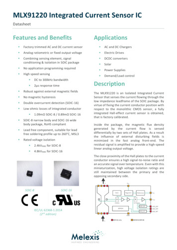
MLX91220 Integrated Current Sensor ICDatasheetFeatures and BenefitsApplications Factory trimmed AC and DC current sensor AC and DC Chargers Analog ratiometric or fixed output voltage Electric Drives Combining sensing element, signalconditioning & isolation in SOIC package DCDC converters Solar No application programming required Power Supplies High speed sensing Demand/Load control DC to 300kHz bandwidth 2µs response time Robust against external magnetic fields No magnetic hysteresis Double overcurrent detection (SOIC-16) Low ohmic losses of integrated conductor 1.09mΩ SOIC-8 / 0.89mΩ SOIC-16SOIC-8 narrow body and SOIC-16 widebody package, RoHS compliant Lead free component, suitable for leadfree soldering profile up to 260 C, MSL3 Rated voltage isolation 2.4kVRMS for SOIC-8 4.8kVRMS for SOIC-16DescriptionThe MLX91220 is an Isolated Integrated CurrentSensor that senses the current flowing through thelow impedance leadframe of the SOIC package. Byvirtue of fixing the current conductor position withrespect to the monolithic CMOS sensor, a fullyintegrated Hall-effect current sensor is obtained,that is factory calibrated.Inside the package, the magnetic flux densitygenerated by the current flow is senseddifferentially by two sets of Hall plates. As a resultthe influence of external disturbing fields isminimized in the fast analog front-end. Theresidual signal is amplified to provide a high-speedlinear analog output voltage.The close proximity of the Hall plates to the currentconductor ensures a high signal-to-noise ratio andan accurate signal over temperature. Even with thisminiaturization, high voltage isolation ratings arestill maintained between the primary and theopposing secondary side.SOIC-8SOIC-16IEC/UL 62368-1:2014(2nd edition)
MLX91220 Integrated Current Sensor ICDatasheetContentsFeatures and Benefits. 1Applications. 1Description . 1Contents. 21. Ordering Information . 42. Functional Diagram . 63. Glossary of Terms . 84. Pinout . 95. Absolute Maximum Ratings . 106. MLX91220 General Electrical Specifications . 117. MLX91220 General Current Specifications . 128. MLX91220 Voltage Isolation Specifications . 139. MLX91220 Timing Specifications . 1410. MLX91220 Accuracy Specifications. 1510.1. Definitions . 1510.2. MLX91220KDx-ABF-117 Specifications. 1710.3. MLX91220KDx-ABR-020 Specifications . 1810.4. MLX91220KDx-ABR-025 Specifications . 1910.5. MLX91220KDx-ABF-025 Specifications. 2010.6. MLX91220KDx-ABR-030 Specifications . 2110.7. MLX91220KDx-ABR-050 Specifications . 2210.8. MLX91220KDx-ABF-050 Specifications. 2310.9. MLX91220KDx-AUF-050 Specifications . 2410.10. MLX91220KDx-ABR-075 Specifications . 2510.11. MLX91220KDx-ABF-075 Specifications . 2611. MLX91220 Overcurrent Detection . 2711.1. General . 2711.2. Electrical Specifications . 2811.3. Internal Overcurrent Detection Principle . 2811.4. External Overcurrent Detection Principle . 29DOC. 3901091220, REVISION 3.0 - MAY 6, 2022Page 2 of 38
MLX91220 Integrated Current Sensor ICDatasheet12. Recommended Application Diagrams . 3012.1. Resistor and Capacitor Values. 3012.2. SOIC8 Application Diagram . 3112.3. SOIC16 Application Diagram . 3112.3.1. OCD functions not used . 3213. Standard information regarding manufacturability with different soldering processes . 3314. ESD Precautions. 3415. Package Information. 3515.1. SOIC-8 150mils - Package Dimensions. 3515.2. SOIC-16 300mils - Package Dimensions. 3615.3. Packaging marks . 3716. Contact . 3717. Disclaimer . 38DOC. 3901091220, REVISION 3.0 - MAY 6, 2022Page 3 of 38
MLX91220 Integrated Current Sensor ICDatasheet1. Ordering InformationProduct CodePackageCurrentMeasurementRangeOutput typeSensitivityOCD levelMLX91220KDC-ABF-025-RESOIC825 AFixed, Bipolar80 mV/AMLX91220KDC-ABF-050-RESOIC850 AFixed, Bipolar40 mV/AMLX91220KDC-AUF-050-RESOIC850 AFixed, Unipolar80 mV/AMLX91220KDC-ABR-020-RESOIC820 ARatiometric, Bipolar100 mV/AMLX91220KDC-ABR-025-RESOIC825 ARatiometric, Bipolar80 mV/AMLX91220KDC-ABR-030-RESOIC830 ARatiometric, Bipolar66 mV/AMLX91220KDC-ABR-050-RESOIC850 ARatiometric, Bipolar40 mV/AMLX91220KDF-ABF-117-RESOIC1617 AFixed, Bipolar120 mV/A14.8 AMLX91220KDF-ABF-025-RESOIC1625 AFixed, Bipolar80 mV/A27.8 AMLX91220KDF-ABF-050-RESOIC1650 AFixed, Bipolar40 mV/A55.6 AMLX91220KDF-AUF-050-RESOIC1650 AFixed, Unipolar80 mV/A55 AMLX91220KDF-ABF-075-RESOIC1675 AFixed, Bipolar26.7 mV/A83.4 AMLX91220KDF-ABR-075-RESOIC1675 ARatiometric, Bipolar26.7 mV/A83.4 AMLX91220KDF-ABR-025-RESOIC1625 ARatiometric, Bipolar80 mV/A27.8 AMLX91220KDF-ABR-050-RESOIC1650 ARatiometric, Bipolar40 mV/A55.6 ATable 1: Ordering informationDOC. 3901091220, REVISION 3.0 - MAY 6, 2022Page 4 of 38
MLX91220 Integrated Current Sensor ICDatasheetLegend:Temperature Code:K: from -40 C to 125 C ambient temperaturePackage Code:“DC” for SOIC-8 NB (Narrow Body – 150mils) package“DF” for SOIC-16 WB (Wide Body – 300mils) packageOption Code:Axx-xxx: die versionxBx-xxx: “B” for bipolar(1) and “U” for unipolarxxF-xxx: “F” for fixed mode output and “R” for ratiometric outputxxx-0xx: “0” for default trimmingxxx-x50: “50” for Full Scale current measurement (corresponding to 2V excursion fromVOQ in bipolar case, and 4V excursion in unipolar case)Packing Form:“RE” for ReelOrdering Example:MLX91220KDC-ABF-050-RETable 2: Legend(1) Bipolar output indicates that the sensor provides a symmetrical output around the 0A point which is set at half the outputvoltage (50% V DD) in case of ratiometric mode, and V REF equals 50%V DD in case of fixed mode. Both designs imply sensingof positive and negative currents.Melexis is continuously expanding its product portfolio by adding new option codes to better meet the needsof our customer’s applications. This table is being updated frequently, please go to the Melexis website todownload the latest version of this datasheet. For custom transfer characteristics, please contact your localMelexis Sales representative or distributor.DOC. 3901091220, REVISION 3.0 - MAY 6, 2022Page 5 of 38
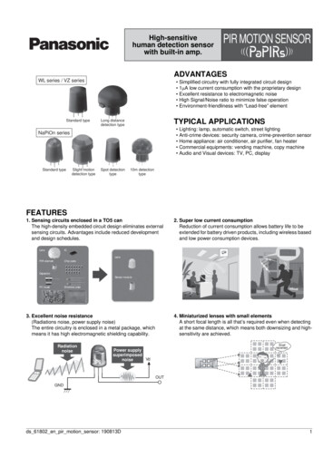
MLX91220 Integrated Current Sensor ICDatasheet2. Functional DiagramFigure 1: Functional Diagram for MLX91220The sensor can be used in 2 different modes, depending on the application. Both modes rely on the output voltageof the sensor being proportional to the flow of current, but the difference resides in the signal reconstruction.Ratiometric ModeFigure 2: Schematic of ratiometric modeNo matter if the VDD line is at 5V or deviating /-10%, the ADC code for a given measured current will always be thesame as the ADC is supplied by the same voltage as the sensor. The sensor has a sensitivity expressed in %VDD/A.DOC. 3901091220, REVISION 3.0 - MAY 6, 2022Page 6 of 38
MLX91220 Integrated Current Sensor ICDatasheetDifferential or Fixed Mode (1)Figure 3: Schemaic of fixed modeIn this particular case the ADC does not necessarily share the same supply voltage with the sensor. For this reason,the sensor is calibrated with an absolute sensitivity regardless of the actual supply voltage. The output signal canbe reconstructed by taking the difference between the output and the reference voltage from the IC. The ADC getsthese two signals as inputs for establishing the sensed current accurately, and is not influenced by the supplyvoltage differences between both sensor and microcontroller, if applicable.ParameterRatiometric ModeDifferential or Fixed ModeVOUT [%VDD]VOUT - VREF [V]Example: output is 2.5V when supply is 5V output is then 50%VDD. If the supply (VDD)increases with 5% to 5.25V the sensor outputwill (for the same measured input current)scale proportionally with the supply voltage,becoming 2.625V, but as a percentage (i.e.ratiometrically seen) it remains at 50% of VDD.Example: output is 2.501V andVREF is 2.501V when supply is 5V.When the supply voltage isincreasing to 5.1V due to supplysystem variation, the sensor willstill maintain the same “fixed”output values VOUT and VREF.OffsetVOUT[0A] 50 [%VDD] (factory trimmed)VREF 2.5 [V] (factory trimmed)VOUT[0A]-VREF 0 [V]Offset ty ratiometricYesNoMeasured Current(VOUT-VOUT[0A]) / Sensitivity(VOUT-VREF) / SensitivityOutput SignalTable 3: Parameters of differential and fixed modes(1) More information can be found in Application Note AN91220 ReferencePin on www.melexis.comDOC. 3901091220, REVISION 3.0 - MAY 6, 2022Page 7 of 38
MLX91220 Integrated Current Sensor ICDatasheet3. Glossary of TermsGauss (G), Tesla (T)Units for the magnetic flux density - 1 mT 10 GTCTemperature Coefficient (in ppm/ C)NCNot ConnectedIPIntegrated PrimaryASPAnalog Signal ProcessingDSPDigital Signal ProcessingACAlternate CurrentDCDirect CurrentEMCElectro-Magnetic CompatibilityFSFull ScaleOCDOverCurrent DetectionTable 4: Glossary of TermsDOC. 3901091220, REVISION 3.0 - MAY 6, 2022Page 8 of 38
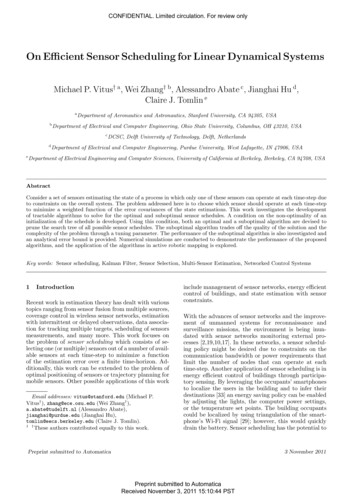
MLX91220 Integrated Current Sensor ICDatasheet4. PinoutFigure 4 SOIC-16 and SOIC-8 pinoutsPINSOIC-8SOIC-16PinFunctionIP Primary Current Path InputIP-Primary Current Path Output9VSSGround Voltage10VREFReference Voltage11NCNot connected12VOUTOutput Voltage13OCDEXTExternal Overcurrent detection14VDDSupply Voltage15VOCEXTExternal Overcurrent threshold voltage16OCDINTInternal Overcurrent Detection123PinFunctionIP Primary Current Path InputIP-Primary Current Path Output5VSSGround Voltage6VREFReference Voltage7VOUTOutput Voltage8VDDSupply Voltage4Table 5: Pinout definitionFor optimal EMC behavior, it is recommended to connect the unused pin (NC) to VSS (see Chapter 12).DOC. 3901091220, REVISION 3.0 - MAY 6, 2022Page 9 of 38
MLX91220 Integrated Current Sensor ICDatasheet5. Absolute Maximum RatingsExceeding the absolute maximum ratings may cause permanent damage. Exposure to absolute maximumrated conditions for extended periods may affect device reliabilityParameterValuePositive Supply Voltage (overvoltage) 8VPositive Supply Voltage (maintaining applicationmode) 6.5 VReverse Supply Voltage- 0.3 VPositive Pin Voltage(1)VDD 0.3 VOutput Sourcing Current 25 mAReverse Pin Voltage(1)- 0.3 VOutput Sinking Current 50 mAOperating Ambient Temperature Range, TA- 40 C to 125 CStorage Temperature Range, TS- 40 C to 150 CMaximum Junction Temperature, TJ (2) 165 CTable 6: Absolute maximum ratings(1) Except for V DD and VSS(2) For more information on how the junction temperature relates to the applied current and ambient temperature range,please refer to section 7.DOC. 3901091220, REVISION 3.0 - MAY 6, 2022Page 10 of 38
MLX91220 Integrated Current Sensor ICDatasheet6. MLX91220 General Electrical SpecificationsDC Operating Parameters at VDD 5V (unless otherwise specified) and for T A as specified by the Temperaturesuffix (K).ParameterSymbolTest ConditionsMinTypMaxUnitsIDDWithout RLOAD, in applicationmode2026mAVOUT output resistanceROUTVOUT 50%VDD, ILOAD 10 mA15 Voltage Reference OutputResistanceRREFVREF 50%VDD, ISINK 5 mA orISOURCE 0.2 mA120200333 Output Capacitive LoadCLOADOutput amplifier stability isoptimized for this typical value04.76nFCommon Mode FieldSensitivity(1)CMFSOutput Short Circuit CurrentISHORTOutput shorted to VDD or VSS PermanentOutput Leakage currentILEAKHigh impedance mode,TA 125 CTJ 150 CSupply CurrentOutput Voltage Linear SwingVOUT LSWFor SOIC160.4mA/GFor SOIC80.4mA/GVDD 4.6 V for Fixed Modeversions210180mA20µA90%VDDTable 7: General electrical specifications(1) Common Mode Field Sensitivity expresses the sensor's susceptibility to a homogenously applied field perpendicular to thepackage surface. The differential measurement cancels out such common mode magnetic fields, but due to the matchingbetween both Hall plate clusters flanking the current conductor, this is not perfect. This parameter expresses the mAoutput error as a result of such 1 mT applied field. It has to be noted, that ma gnetic fields generated by nearbyconductors are not homogenous but introduce gradients. More information in this regard can be found in ApplicationNote AN91220 ExternalFieldImmunity on www.melexis.comDOC. 3901091220, REVISION 3.0 - MAY 6, 2022Page 11 of 38
MLX91220 Integrated Current Sensor ICDatasheet7. MLX91220 General Current SpecificationsDC Operating Parameters at V DD 5V (unless otherwise specified) and for T A as specified by the Temperaturesuffix (K).ParameterSymbolTest ConditionsElectrical Resistance of thePrimary Current PathRIP SOIC8RIP SOIC16TA 25 C1.090.89mΩmΩIPMAXOption Code ABx-117Option Code ABx-025Option Code ABx-030Option Code ABx-050Option Code AUF-050Option Code ABx-07516.72530505075AAAAAAIPNOMOption Code ABx-117Option Code ABx-025Option Code ABx-030Option Code ABx-050Option Code AUF-050Option Code ABx-0756.71012202030AAAAAAMeasurement RangeNominal CurrentLinearity ErrorCurrent Capability(1)MinTypMaxUnitsNLCurrent in range IPNOM, TA 25 C 0.3%FSNLCurrent in range IPMAX, TA 25 C 0.6%FSIPC85 SOIC8IPC25 SOIC8Continuous, TA -40 to 85 CContinuous, TA 25 C 25 40AAIPC85 SOIC16IPC25 SOIC16Continuous, TA -40 to 85 CContinuous, TA 25 C 30 45AATable 8: General current specifications(1) Current capability based on the reference Melexis PCB made of 2x 105 µm copper layer without any forced air or other form ofcooling. Continuous or RMS current ranges in application are typically higher than this. More information can be found inApplication Notes AN91220 FuseCurrent Capability and AN91220 ThermalManagement on www.melexis.com.DOC. 3901091220, REVISION 3.0 - MAY 6, 2022Page 12 of 38
MLX91220 Integrated Current Sensor ICDatasheet8. MLX91220 Voltage Isolation SpecificationsParameterDielectric Strength Test Voltage (1) (2)SymbolTest ConditionsVISO SOIC8IEC 62368-1:2014 (secondedition)VISO SOIC16DCL SOIC8Clearance (primary to secondary)DCR SOIC8DCR SOIC16Comparative tracking indexWorking Voltage for Basic IsolationShortest path along body2400VRMS4800VRMS4mm8.1mm3.6mm7.1mm600CTIVWV SOIC8UnitsShortest distance through airDCL SOIC16Creepage (primary to secondary)Rating500VRMSIEC 62368-1:2014 (2nd edition)707VDCBased on Pollution degree 2,Material Group II1000VRMS1414VDC(3)VWV SOIC16Table 9: Voltage isolation specifications(1) Agency type tested, measured between IP (pin 1-4 on SOIC8, pin 1-8 on SOIC16) and Secondary side (pin 5-8 on SOIC8, pin9-16 on SOIC16).(2) Melexis performs routine production-line tests, for all SOIC8 & SOIC16 devices produced.(3) Tension de service pour une isolation principale spécifiée pour un Degré de Pollution 2 et un groupe de matériaux II selonla norme IEC/UL-62368-1:2014 (2ème édition)DOC. 3901091220, REVISION 3.0 - MAY 6, 2022Page 13 of 38
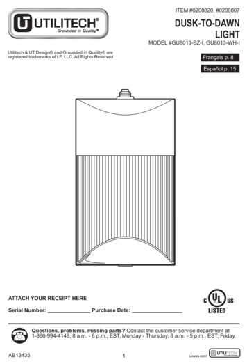
MLX91220 Integrated Current Sensor ICDatasheet9. MLX91220 Timing SpecificationsDC Operating Parameters at V DD 5V (unless otherwise specified) and for T A as specified by the Temperaturesuffix (K).ParameterSymbolTest ConditionsStep Response TimeTRESPDelay between the input signalreaching 90% and the outputreaching 90% (see Figure 5)BandwidthBW-3dB, TA 25 CPower on Delay(1)TPODVREF capacitor 47nFMinTypMaxUnits2μs300kHz0.6msTable 10: Timing specificationsin, Vout100%Responsetime90%time1 µsFigure 5: Response Time definition(1) During the Power-on delay, the output will remain within the 10% fault band at all time.DOC. 3901091220, REVISION 3.0 - MAY 6, 2022Page 14 of 38
MLX91220 Integrated Current Sensor ICDatasheet10. MLX91220 Accuracy Specifications10.1. DefinitionsThermal Reference DriftThe thermal reference drift is the variation of the reference voltage (V REF) over temperature. It is expressed inppm/ C. ΔT𝑉𝑅𝐸𝐹 (𝑉𝑟𝑒𝑓[125 ]1 1) . 106𝑉𝑟𝑒𝑓[35 ](125 35) ΔT𝑉𝑅𝐸𝐹 (𝑉𝑟𝑒𝑓[ 40 ]1 1) . 106𝑉𝑟𝑒𝑓[35 ]( 40 35)Voltage Output QuiescentVOQ corresponds to the output when no current is flowing through the MLX91220 at T A 25 C.Thermal Offset DriftΔTVOQ corresponds to variation of V OQ in temperature.SensitivityThe sensitivity is the ratio between the output of the MLX91220 and the input current.For ratiometric devices, as the output will scale with the supply, sensitivity is expressed as [%V DD]/A.For fixed devices, the output does not vary with the V DD, sensitivity is thus expressed as mV/A.Linearity ErrorThe linearity error is the deviation of the output from the expected linear behaviour. To obtain the linearityerror, the current is swept from -𝐼𝑃𝑀 to 𝐼𝑃𝑀 . To decorrelate the thermal drift from the linearity error, thejunction temperature should be fixed below 50 C.𝑁𝐿 𝑉𝑜𝑢𝑡 [𝐼] 𝐵𝐸𝑆𝑇𝐹𝐼𝑇(𝑉𝑜𝑢𝑡 [𝐼]). 100 [%𝐹𝑆]𝑉𝑜𝑢𝑡 [𝐼𝑃𝑀 ] 𝑉𝑜𝑢𝑡 [ 𝐼𝑃𝑀 ]DOC. 3901091220, REVISION 3.0 - MAY 6, 2022Page 15 of 38
MLX91220 Integrated Current Sensor ICDatasheetRatiometry Offset and Sensitivity ErrorRatiometric ModeIn Ratiometric mode, V OUT and VREF are scaled with the supply voltage. 𝑉𝐷𝐷𝑛𝑜𝑚 5𝑉Ratiometric VOQ Error:ΔR 𝑉𝑂𝑄 𝑉𝑂𝑄 [𝑉𝐷𝐷𝑛𝑜𝑚 ] 𝑉𝑂𝑄 [𝑉𝐷𝐷𝑛𝑜𝑚 �𝑛𝑜𝑚 10%Ratiometric Sensitivity Error:ΔR𝑆 100. (1 𝑆[𝑉𝐷𝐷𝑛𝑜𝑚 10%]𝑉. 𝑉 𝐷𝐷𝑛𝑜𝑚)𝑆[𝑉𝐷𝐷𝑛𝑜𝑚 ]𝐷𝐷𝑛𝑜𝑚 10%[%]Fixed ModeIn Fixed mode, V OUT and VREF are not scaled with the supply voltage. Ideally, they do not vary. 𝑉𝐷𝐷𝑛𝑜𝑚 5𝑉Non-Ratiometric VOQ Error:ΔR 𝑉𝑂𝑄 𝑉𝑂𝑄 [𝑉𝐷𝐷𝑛𝑜𝑚 10%] 𝑉𝑂𝑄 [𝑉𝐷𝐷𝑛𝑜𝑚 ] [𝑚𝑉]Non-Ratiometric Sensitivity Error:ΔR𝑆 (𝑆[𝑉𝐷𝐷𝑛𝑜𝑚 10%] 1) . 100 [%]𝑆[𝑉𝐷𝐷𝑛𝑜𝑚 ]DOC. 3901091220, REVISION 3.0 - MAY 6, 2022Page 16 of 38
MLX91220 Integrated Current Sensor ICDatasheet10.2. MLX91220KDx-ABF-117 SpecificationsDC Operating Parameters at V DD 5V (unless otherwise specified), for TA as specified by the Temperature suffix(K) and for TJ 150 C.ParameterSymbolTest ConditionsMinPrimary currentIPMFor VDD 4.6 V-16.7Nominal Supply VoltageVDDFor I such as VOUT VDD-0.1 V4.5Voltage ReferenceVREFTA 25 C. No resistive load onVref pin2.48Thermal Reference DriftVoltage Output QuiescentΔTVREFVOQNo current flowing throughIP, VOUT-VREF, TA 25 CNo resistive load on VOUT andVREFΔRVOQTA 25 C and for 10% VDDThermal Offset DriftΔTVOQReferred to TA 25 C, IP 0ALifetime Offset DriftΔLVOQSMaxUnits16.7A55.5V2.52.52V 150ppm/ C-7.5-637.563mVmA-55mV 10 84mVmAVariation versus 25 CRatiometry Offset ErrorSensitivityTyp 5 42 2At TA 25 CFor Tj 50 C-1118.8mV1121.2%mV/A0.6% 1 1.5%S 1 2%S120Ratiometry Sensitivity ErrorΔRSTA 25 C and for 10% VDD-0.6Thermal Sensitivity DriftΔTSCurrent range IPMAXSensitivity Drift over lifetimeΔLSOutput Noise SpectralDensityNSDIP 0 A, TA 25 Cwithin BW 1 100kHz179µA/ HzOutput RMS NoiseNRMSIP 0 A, TA 25 CBW 300kHz116mARMSOCDINT Threshold Current(1)IOCD14.8AOCDINT Accuracy(1)εIOCD9.717.6%%OCD EXT threshold error(1)εEOCDTA 25 CTA -40 C to 85 C-66%Table 11: MLX91220KDx-ABF-117 specifications(1) For SOIC16 versionDOC. 3901091220, REVISION 3.0 - MAY 6, 2022Page 17 of 38
MLX91220 Integrated Current Sensor ICDatasheet10.3. MLX91220KDx-ABR-020 SpecificationsDC Operating Parameters at V DD 5V (unless otherwise specified),for T A as specified by the Temperature suffix(K) and for Tj 150 C.ParameterSymbolTest ConditionsMinPrimary currentIPM-20Nominal Supply VoltageVDD4.5Voltage Output QuiescentVOQRatiometry Offset ErrorΔRVOQThermal Offset DriftΔTVOQLifetime Offset DriftΔLVOQSensitivitySTyp5MaxUnits20A5.5VNo current flowing throughIP, VOUT –VDD/2, TA 25 CNo resistive load on VOUT andVREF-7.5-757.575mVmATA 25 C and for 10% VDD-1010mV 7.5 75mVmAReferred to TA 25 C, IP 0A 5 50 2At TA 25 CFor Tj 50 CRatiometry Sensitivity ErrorΔRSTA 25 C and for 10% VDDThermal Sensitivity DriftΔTSCurrent range IPMAXSensitivity Drift over lifetimeΔLSOutput Noise SpectralDensityNSDOutput RMS NoiseNRMSOCDINT Threshold Current(1)IOCDOCDINT Accuracy(1)εIOCDOCD EXT threshold error(1)εEOCD-199100mV1101 0.5IP 0 A, TA 25 Cwithin BW 1 100kHz% 1 1.5%S 1 2%S186IP 0 A, TA 25 CBW 300kHzµA/ HzmARMS120TA 25 CTA -40 C to 85 C-6%mV/A22.2A812%%6%Table 12: MLX91220KDx-ABR-020 specifications(1) For SOIC16 versionDOC. 3901091220, REVISION 3.0 - MAY 6, 2022Page 18 of 38
MLX91220 Integrated Current Sensor ICDatasheet10.4. MLX91220KDx-ABR-025 SpecificationsDC Operating Parameters at V DD 5V (unless otherwise specified), for TA as specified by the Temperature suffix(K) and for TJ 150 C.ParameterSymbolTest ConditionsMinPrimary currentIPM-25Nominal Supply VoltageVDD4.5Voltage Output QuiescentVOQRatiometry Offset ErrorΔRVOQThermal Offset DriftΔTVOQLifetime Offset DriftΔLVOQSensitivitySTyp5MaxUnits25A5.5VNo current flowing throughIP, VOUT –VDD/2, TA 25 CNo resistive load on VOUT andVREF-7.5-947.594mVmATA 25 C and for 10% VDD-1010mV 7.5 94mVmAReferred to TA 25 C, IP 0A 5 63 2At TA 25 CFor Tj 50 C-179.280mV180.8 0.5%mV/ARatiometry Sensitivity ErrorΔRSTA 25 C and for 10% VDDThermal Sensitivity DriftΔTSCurrent range IPMAXLifetime Sensitivity DriftΔLSOutput Noise SpectralDensityNSDIP 0 A, TA 25 Cwithin BW 1 100kHz190µA/ HzOutput RMS NoiseNRMSIP 0 A, TA 25 CBW 300kHz129mARMSOCDINT Threshold Current(1)IOCD27.8AOCDINT Accuracy(1)εIOCD7.511.5%%OCD EXT threshold error(1)εEOCDTA 25 CTA -40 C to 85 C-6% 1 1.5%S 1 2%S6%Table 13: MLX91220KDx-ABR-025 specifications(1) For SOIC16 versionDOC. 3901091220, REVISION 3.0 - MAY 6, 2022Page 19 of 38
MLX91220 Integrated Current Sensor ICDatasheet10.5. MLX91220KDx-ABF-025 SpecificationsDC Operating Parameters at V DD 5V (unless otherwise specified), for TA as specified by the Temperature suffix(K) and for TJ 150 C.ParameterSymbolTest ConditionsMinPrimary currentIPMFor VDD 4.6 V-25Nominal Supply VoltageVDDFor I such as VOUT VDD-0.1 V4.5Voltage ReferenceVREFTA 25 C. No resistive load onVref pin2.48Thermal Reference DriftVoltage Output QuiescentΔTVREFVOQRatiometry Offset ErrorΔRVOQThermal Offset DriftΔTVOQLifetime Offset DriftΔLVOQSensitivitySTypMaxUnits25A55.5V2.52.52V 150ppm/ C-7.5-947.594mVmA-55mV 7.5 94mVmAVariation versus 25 CNo current flowing throughIP, VOUT-VREF, TA 25 CNo resistive load on VOUT andVREFTA 25 C and for 10% VDDReferred to TA 25 C, IP 0A 5 63 2At TA 25 CFor Tj 50 C-179.2-0.6mV180.8%mV/A0.6% 1 1.5%S 1 2%S80Ratiometry Sensitivity ErrorΔRSTA 25 C and for 10% VDDThermal Sensitivity DriftΔTSCurrent range IPMAXLifetime Sensitivity DriftΔLSOutput Noise SpectralDensityNSDIP 0 A, TA 25 Cwithin BW 1 100kHz190µA/ HzOutput RMS NoiseNRMSIP 0 A, TA 25 CBW 300kHz129mARMSOCDINT Threshold Current(1)IOCD27.8AOCDINT Accuracy(1)εIOCD7.511.5%%OCD EXT threshold error(1)εEOCDTA 25 CTA -40 C to 85 C-66%Table 14: MLX91220KDx-ABF-025 specifications(1) For SOIC16 versionDOC. 3901091220, REVISION 3.0 - MAY 6, 2022Page 20 of 38
MLX91220 Integrated Current Sensor ICDatasheet10.6. MLX91220KDx-ABR-030 SpecificationsDC Operating Parameters at V DD 5V (unless otherwise specified), for TA as specified by the Temperature suffix(K) and for TJ 150 C.ParameterSymbolTest ConditionsMinPrimary currentIPM-30Nominal Supply VoltageVDD4.5Voltage Output QuiescentVOQRatiometry Offset ErrorΔRVOQThermal Offset DriftΔTVOQLifetime Offset DriftΔLVOQSensitivitySTyp5MaxUnits30A5.5VNo current flowing throughIP, VOUT –VDD/2, TA 25 CNo resistive load on VOUT andVREF-7.5-1127.5112mVmATA 25 C and for 10% VDD-1010mV 7.5 112mVmAReferred to TA 25 C, IP 0A 5 75 2At TA 25 CFor Tj 50 C-166.066.7mV167.4 0.5%mV/ARatiometry Sensitivity ErrorΔRSTA 25 C and for 10% VDDThermal Sensitivity DriftΔTSCurrent range IPMAXLifetime Sensitivity DriftΔLSOutput Noise SpectralDensityNSDIP 0 A, TA 25 Cwithin BW 1 100kHz197µA/ HzOutput RMS NoiseNRMSIP 0 A, TA 25 CBW 300kHz131mARMSOCDINT Threshold Current(1)IOCD33.7AOCDINT Accuracy(1)εIOCD711%%OCD EXT threshold error(1)εEOCDTA 25 CTA -40 C to 85 C-6% 1 1.5%S 1 2%S6%Table 15: MLX91220KDx-ABR-030 specifications(1) For SOIC16 versionDOC. 3901091220, REVISION 3.0 - MAY 6, 2022Page 21 of 38
MLX91220 Integrated Current Sensor ICDatasheet10.7. MLX91220KDx-ABR-050 SpecificationsDC Operating Parameters at V DD 5V (unless otherwise specified), for TA as specified by the Temperature suffix(K) and for TJ 150 C.ParameterSymbolTest ConditionsMinPrimary currentIPM-50Nominal Supply VoltageVDD4.5Voltage Output QuiescentVOQRatiometry Offset ErrorΔRVOQThermal Offset DriftΔTVOQLifetime Offset DriftΔLVOQSensitivitySTyp5MaxUnits50A5.5VNo current flowing throughIP, VOUT –VDD/2, TA 25 CNo resistive load on VOUT andVREF-7.5-1887.5188mVmATA 25 C and for 10% VDD-1010mV 7.5 188mVmAReferred to TA 25 C, IP 0A 5 125 2At TA 25 CFor Tj 50 C-139.640mV140.4 0.5%mV/ARatiometry Sensitivity ErrorΔRSTA 25 C and for 10% VDDThermal Sensitivity DriftΔTSCurrent range IPMAXLifetime Sensitivity DriftΔLSOutput Noise SpectralDensityNSDIP 0 A, TA 25 Cwithin BW 1 100kHz186µA/ HzOutput RMS NoiseNRMSIP 0 A, TA 25 CBW 300kHz126mARMSOCDINT Threshold Current(1)IOCD55.6AOCDINT Accuracy(1)εIOCD4.26.2%%OCD EXT threshold error(1)εEOCDTA 25 CTA -40 C to 85 C-6% 1 1.5%S 1 2%S6%Table 16: MLX91220KDx-ABR-050 specifications(1) For SOIC16 versionDOC. 3901091220, REVISION 3.0 - MAY 6, 2022Page 22 of 38
MLX91220 Integrated Current Sensor ICDatasheet10.8. MLX91220KDx-ABF-050 SpecificationsDC Operating Parameters at V DD 5V (unless otherwise specified), for TA as specified by the Temperature suffix(K) and for TJ 150 C.ParameterSymbolTest ConditionsMinPrimary currentIPMFor VDD 4.6 V-50Nominal Supply VoltageVDDFor I such as VOUT VDD-0.1 V4.5Voltage ReferenceVREFTA 25 C. No resistive load onVref pin2.48Thermal Reference DriftVoltage Output QuiescentΔTVREFVOQRatiometry Offset ErrorΔRVOQThermal Offset DriftΔTVOQLifetime Offset DriftΔLVOQSensitivitySTypMaxUnits50A55.5V2.52.52V 150ppm/ C-7.5-1887.5188mVmA-55mV 7.5 188mVmAVariation versus 25 CNo current flowing throughIP, V
Product Code Package Current Measurement Range Output type Sensitivity OCD level MLX91220KDC-ABF-025-RE SOIC8 25 A Fixed, Bipolar 80 mV/A MLX91220KDC-ABF-050-RE SOIC8 50 A Fixed, Bipolar 40 mV/A MLX91220KDC-AUF-050-RE SOIC8 50 A Fixed, Unipolar 80 mV/A MLX91220KDC-ABR-020-RE SOIC8 20 A Ratiometric, Bipolar 100 mV/A