Transcription
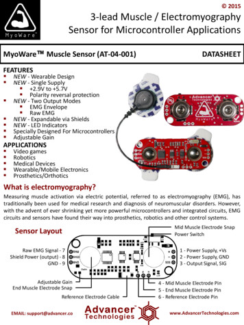
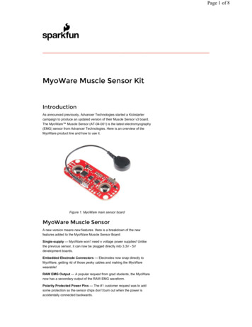
Page 1 of 8 MyoWare Muscle Sensor KitIntroductionAs announced previously, Advancer Technologies started a Kickstartercampaign to produce an updated version of their Muscle Sensor v3 board.The MyoWare Muscle Sensor (AT-04-001) is the latest electromyography(EMG) sensor from Advancer Technologies. Here is an overview of theMyoWare product line and how to use it.Figure 1. MyoWare main sensor boardMyoWare Muscle SensorA new version means new features. Here is a breakdown of the newfeatures added to the MyoWare Muscle Sensor Board:Single-supply — MyoWare won’t need voltage power supplies! Unlikethe previous sensor, it can now be plugged directly into 3.3V - 5Vdevelopment boards.Embedded Electrode Connectors — Electrodes now snap directly toMyoWare, getting rid of those pesky cables and making the MyoWarewearable!RAW EMG Output — A popular request from grad students, the MyoWarenow has a secondary output of the RAW EMG waveform.Polarity Protected Power Pins — The #1 customer request was to addsome protection so the sensor chips don’t burn out when the power isaccidentally connected backwards.
Page 2 of 8ON/OFF Switch — Speaking of burning out the board, AdvancerTechnologies also added an on-board power switch so you can test yourpower connections more easily. It’s also handy for saving power.LED Indicators — Advancer Technologies added two on-board LEDs oneto let you know when the MyoWare’s power is on and the other will brightenwhen your muscle flexes.For more information, please have a look at the official MyoWare MuscleSensor datasheet.What is electromyography (EMG)?An EMG is used to record (graph) the electrical activity (electro) of muscles(myo).Embedded Electrode ConnectorsThe embedded electrode connectors allow you to stick the board right tothe target muscle and avoid the hassle of wires.Embedded electrode connectorsThe embedded snap connectors mate well with our Biomedical Sensor Pad(10 pack).Cable ShieldThere may still be cases where you want to mount the sensor pads awayfrom the other hardware. For these cases, we sell the MyoWare CableShield.MyoWare Cable Shield
Page 3 of 8The cable shield provides a jack where you can attach the three electrodecable shown here.Three electrode cableInstead of attaching the sensor pads to the MyoWare Muscle Sensor,attach them to the end of the cable. Both sets of contacts are connected, somake sure to only use one pad for each (Reference, End, and Middle).Power ShieldMyoWare Power ShieldThe MyoWare Power Shield is designed to take two coin cell batteries suchas some standard CR2032s. They are connected in parallel for extendedcapacity at a nominal 3.0V. One thing to note is that due to the size of thebatteries, the remote cable header can’t be passed through. If you needaccess to these connections, this Power Shield must be stacked above theboard(s) that need access.Battery power allows for a cleaner signal and also eliminates the possibilityof creating a dangerous current path to the power grid.Proto Shield
Page 4 of 8MyoWare prototyping shieldThe MyoWare Proto Shield passes all signals to a bit of protoboard. Usethis area to solder on whatever custom circuitry you can come up with.The Cable Shield and the Proto Shield have two rows of 3-pin platedthrough holes on each end. This allows ‘standard’ 0.1" headers to be usedto stack them with other boards. Use the outer rows to connect to theMuscle Sensor, connect these two boards with the inner rows. The outerrow on the top can also be used to stack another shield on top for a total of4 boards in a stack.LED ShieldFor those users looking for a large display of the signal level, we offer thethe MyoWare LED Shield.MyoWare LED ShieldThe LED shield provides a large 10-segment bar graph corresponding tothe level of the muscle signal measured. This shield is likely to be the topboard in a stack. Solder on some 1x3 male headers, and plug it into thesensor board. The power is supplied on the LED shield, but controlled bythe power switch on the sensor. Once the stack is assembled, snap onsome electrodes, and stick the sensor on the target muscle.
Page 5 of 8MyoWare LED Shield on an armThe more muscle activation measured, the higher up the board the lit LEDswill go. In the image above, the two segments near the ‘MIN’ label are lit,and, if the voltage measured were to increase, the segments to the leftwould begin to light until the last one labeled ‘MAX’ is reached. The LEDsare bright enough to be seen in full light, but really glow nice in low light.MyoWare LED Shield in the darkPutting it All TogetherAs mentioned above, there are two ways to attach the sensor pads to auser. They can be attached directly to the sensor board, or to the the end ofa cable via the MyoWare Cable Shield.In the image below, the left most electrode connection should be connectedto the muscle being measured. This is equivalent to using the red insulatedconductor on the cable. The mid muscle electrode on the right breaks outon the black snap. The reference electrode has continuity with the bluesnap on the cable.MyoWare sensor layoutAs shown in the image above, there are three rows of three 0.1" spacedplated through holes. On the right is the power supply Vs, & ground, alongwith the processed output signal (holes 1, 2, & 3).Along the long edge near the mid muscle electrode snap are the thru-holesfor remote electrode connection (holes 4, 5, & 6).
Page 6 of 8On the opposite end are three ‘outputs’. Hole 7 is the raw, unprocessedEMG signal. Hole 8 is the switched power. Power goes into the board viahole 1, is switched, and comes back out hole 8 ( if you believe in passivesign convention (PSC) ). Hole 9 is the ground reference for the switchedpower.The shields come with assorted support for these pins. Some shields suchas the Power Shield don’t support the remote connections. If you needaccess to these pins the boards that use or can pass them through must golower in the stack. Both the Cable Shield and the Proto Shield have thisconnection capability.Danger! The power shield and the LED shield both provide power, butat slightly different voltages. Don't use both of these shields at thesame time.MyoWare Power Shield (top view)MyoWare LED Shield (top view)MyoWare Cable Shield (bottom view)MyoWare Proto Shield (top view)Take note of the second row of holes on the Cable and Proto shields. Thisallows for stacking multiple shields using standard 0.1" headers or thestackable variety.
Page 7 of 8Break Away Headers StraightFemale Headers PRT-00 115 PRT- 00116Stackable Header - 3 Pin(Female, 0.1") PRT- 13875The MyoWare sensor should be populated with female headers. If using thestackable headers supplied with the kit, it is likely that you will want to flushcut the long leads from the bottom. It’s possible to use a setup including thecable shield, where you might want to leave them, so we’ve given thatoption. The shield desired to mate with the MyoWare sensor should in mostcases have male headers populated on the outer bottom rows to mate withthe female headers. If using the parts provided on the kit, these maleheaders will likely be the bottom half of stackable headers. The top side ofthis shield can then be populated with female headers. The next board inthe stack will then need male headers on the bottom inside. This shield canhave female headers mounted to the outside row on the top side.To make stacking easier, the MyoWare Muscle Sensor Kit includes 3-pinstackable headers. Using these on all of the shields allows for easystacking in more configurations. Note: We have included three 1x3 maleheaders in the kit. The normal use case will to be to put two of them on theLED shield, but some of you might want a clean top surface on the cable orproto shields so we thew in an extra one for this option.3 pin stackable headerResources and Going FurtherThanks for reading. For more information on the MyoWare product line,please visit the following links. Official MyoWare datasheet
Page 8 of 8 Advancer Technologies Website MyoWare GitHub Repository For more cool projects and ideas,check out the following SparkFun tutorials.Hackers in Residence Hacking MindWave MobileAD8232 Heart Rate MonitorHookup GuideReview, teardown, and hackingtutorial for the MindWave Mobile, a 99 commercial grade EEG sensor.Learn how to create your very ownheart rate monitor.MyoWare Muscle Sensor KitMAX30105 Particle and PulseOx Sensor Hookup GuideLine of products to work with theMyoWare muscle sensor fromAdvancer TechnologiesThe SparkFun MAX30105 ParticleSensor is a flexible and powerfulsensor enabling sensing of distance,heart rate, particle detection, eventhe blinking of an eye. Get ready.Set. -muscle-sensor-kit? ga 1.210083858.648079. 1/16/2017
MyoWare Muscle Sensor Kit Introduction As announced previously, Advancer Technologies started a Kickstarter campaign to produce an updated version of their Muscle Sensor v3 board. The MyoWare Muscle Sensor (AT-04-001) is the latest electromyography (EMG) sensor from Advancer Technologies. Here is an overview of the MyoWare product line and how to use it. Figure 1. MyoWare main sensor