Transcription
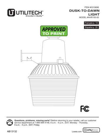
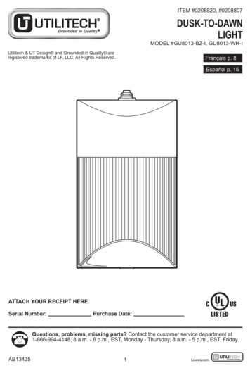
ITEM #0208820, #0208807DUSK-TO-DAWNLIGHTMODEL #GU8013-BZ-I, GU8013-WH-IUtilitech & UT Design and Grounded in Quality areregistered trademarks of LF, LLC. All Rights Reserved.Français p. 8Español p. 15ATTACH YOUR RECEIPT HERESerial Number:Purchase Date:Questions, problems, missing parts? Contact the customer service department at1-866-994-4148, 8 a.m. - 6 p.m., EST, Monday - Thursday, 8 a.m. - 5 p.m., EST, Friday.AB134351Lowes.com
PACKAGE TY11PARTCDDESCRIPTIONBulbDusk-to-Dawn SensorQUANTITY11HARDWARE CONTENTS (shown actual size)AABBWire NutMachineScrewSensorCapQty. 3Qty. 4Qty. 1CCDDSensorHoodQty. 1SAFETY INFORMATIONWARNING Shut off power at the circuit breaker or fuse panel before removing the old fixture orinstalling the new one.CAUTION DO NOT USE THIS FIXTURE WITH A DIMMING CIRCUIT. If you presently have dimmer controls,you will need to remove them, and replace them with regular electrical switches. If you have a threeway dimmer, you will have to replace it with a regular three-way switch. If you are unfamiliar withelectrical installations, it is recommended you have a qualified electrician do your installation.HgLAMP CONTAINS MERCURYManage in accordance with Spills, Disposal and Site Cleanup Requirements.In case of breakage, follow clean-up procedures provided by contacts IONBefore beginning assembly of product, make sure all parts are present. Compare parts withpackage contents list and diagram above. If any part is missing or damaged, do not attempt toassemble the product. Contact customer service for replacement parts.Estimated Assembly Time: 45 minutesTools Required for Assembly (not included): Flathead Screwdriver, Safety Glasses, Electrical TapePhillips head Screwdriver, Wire Cutters, Pliers, Wire Strippers, Step Ladder, Level.2Lowes.com
ASSEMBLY INSTRUCTIONSWith power disconnected to your electrical box, remove the old fixture. If your old fixture is attached toan electrical box having more than two (2) wire leads, it is recommended you use tape and markingsto keep track of which wires were attached to each other.1. Screw the machine screws (BB) into the electrical boxuntil there is about 3/8 in. between the wall and theunderside of the machine screw (BB) head (Fig. 1).1BBHardware UsedBBMachineScrew3/8 in.x21 cmBB2. Remove the diffuser (B) from the fixture (A) bysqueezing the tab on the bottom of the diffuser (B)while pulling the diffuser (B) up and out of thefixture (A) (Fig. 2).2DAB3. Once you have determined the position the fixture (A)will be mounted, mark the corresponding knock-outsand remove them (Fig. 3). CAREFULLY REMOVE THEKNOCK-OUT BY HAMMERING A FLATHEADSCREWDRIVER OR PUNCH UNTIL THE SURFACEBREAKS. If the knock-out did not break free, use pliersand bend it back and forth until it snaps off.33ALowes.comBB
ASSEMBLY INSTRUCTIONS4. For safety and proper operation, the fixture (A) mustbe properly grounded. If you are unfamiliar with themethods of properly grounding your fixture (A), consult aqualified electrician. A green or bare copper ground wireis pre-attached to your fixture (A). If the electrical box isplastic and has a green or bare copper grounding wireinside, the bare end of the fixture grounding wire mustbe secured to the green grounding wire inside theelectrical box using one of the wire nuts (AA) (Fig. 4). Ifthe electrical box is metal and contains no ground wireas part of a grounded electrical system, refer to STEP 6for grounding instructions.4BBAABBHardware UsedAAWire Nutx15. Connect the supply leads from the electrical box to the 5fixture wire leads using the wire nuts (AA) supplied inyour installation hardware kit as per the illustration. Theblack lead from the fixture goes to the black supplylead and the white lead from the fixture goes to thewhite supply lead (Fig. 5). Secure the wire nuts properlyto prevent the wires from coming loose. Tape the wirenuts to the wire using electrical tape. Carefully push theexcess wires back inside the electrical box.BBAAAAAHardware UsedAAWire Nutx2BBAAAA6. Position the fixture pan (A) over the electrical box andline them up the slots in the fixture pan with the slots inthe electrical box. Hold in place and tighten the machinescrews (BB) very tightly. The hardware kit includes two(2) screws (BB) specifically designed to ground thefixture (A) to a metal electrical box. Tighten the screws(BB) until the underside of the screwhead is cuttingthrough the paint on the fixture's (A) surface and thepan is tight up against the mounting surface (Fig. 6).The underside of the screwhead is designed with aserrated edge or is affixed with one that when tightenedagainst a painted surface will cut through to makecontact with the metal underneath. In order for a groundto be made, the screws (BB) must be tightened to makea bare metal to bare metal contact.Hardware UsedBBMachineScrew6ABBBBx24Lowes.com
ASSEMBLY INSTRUCTIONS7. In the event of outdoor installation, you will need touse silicon or other waterproof caulk around the outerperimeter of the fixture (A) pan to prevent water seepinginto the wiring compartment (Fig. 7).7A8. Insert the proper GU24 base 13W compactfluorescent bulb (C) into the socket (Fig. 8). Hold thebulb (C) by its base, insert the pins into the 2 curvedslots in the bulb socket and twist clockwise until thebulb (C) "seats". The bulb can only go into the socketone way. Do NOT force the bulb (C). CAUTION: DONOT HOLD THE BULB (C) BY THE GLASS DURINGINSERTION OR REMOVAL TO PREVENTACCIDENTAL BREAKAGE! HOLD THE BULB (B) BYTHE PLASTIC BASE.9. Slide the diffuser (B) into the fixture (A) and push on the tabat the bottom of the diffuser (B) so the diffuser (B) locks intoplace (Fig. 9).Restore power to the electrical box to make sure yourfixture (A) is working properly.8AC9ABBAOPERATING INSTRUCTIONSYour indoor/outdoor lantern is controlled by a dusk-to-dawn photo light sensor (E). Therefore, for yourlantern to work properly, the electrical switch to the lantern MUST be turned ON at ALL times.1. If your security light cycles ON and OFF, thedusk-to-dawn sensor (D) may be activating due to reflectedlight from a nearby surface. Place the sensor hood (DD)firmly over the dusk-to-dawn sensor (Fig. 1). This shouldprevent extraneous light from ‘tripping’ the dusk-to-dawnsensor (D).Hardware UsedDDSensorHoodx151DDADLowes.com
OPERATING INSTRUCTIONS2. To disable the dusk-to-dawn sensor (D), you will need toinstall the sensor cap (CC) over the dusk-to-dawn sensor(D) (Fig. 2). This will prevent the dusk-to-dawn sensor (D)from controlling the ON/OFF function, and should allow youto control the fixture (A) with the wall switch.2CCHardware UsedCCSensorCapx1DABULB REPLACEMENT INSTRUCTIONSYour bulb should last up to 10,000 hours in normal use. When bulb replacement is necessary, youmust replace the bulb with a CFL13W self-ballasted GU24 base fluorescent bulb. These bulbs arereadily available at your local home center and most larger hardware stores.Before replacing bulb (C), shut off power to the fixture at the circuit breaker or fuse panel. Allowsufficient time for fixture and lamp to cool.1. Remove the diffuser (B) from the fixture (A) by squeezing the sides of the diffuser (B) while pullingthe diffuser (B) up and out of the fixture (A).2. Remove the defective bulb by grasping it by the plastic base and unscrewing it from the bulbsocket 1/4 turn in counterclockwise direction.3. Install the new bulb in the same manner youremoved the old bulb (Fig. 1). Slide the diffuser (B) intothe fixture (A) and push on the tab at the bottom of thediffuser (B) so the diffuser (B) locks into place. Restorepower to the fixture.1AC4. Dispose of the old lamp(s) in accordance with local, state, and/or federal laws, or go towww.lamprecycle.org for more information.CARE AND MAINTENANCEYou may want to periodically clean the fixture using a mild, non-abrasive glass cleaner and softcloth. Do NOT use solvents or cleaners containing abrasive agents. When cleaning the fixture,make sure you have the power turned off and do not spray liquid cleaner directly onto the bulb,socket, ballast, or wiring.6Lowes.com
TROUBLESHOOTINGMinor problems often can be fixed without the help of an electrician. Before doing any work on thefixture, shut off power supply at the circuit breaker panel to avoid electrical shock.PROBLEMPOSSIBLE CAUSECORRECTIVE ACTIONFixture doesn’t light.1. Check circuit breaker or wall switch.2. Check wire splices.3. Replace bulb(s).4. Replace switch.5. Cap sensor or wait until dark.1. Power is off.2. Bad wire connection.3. Defective bulb(s).4. Defective wall switch.5. Photo sensor is inactive.1. Crossed wires or power wireCircuit breaker tripsis grounded out.when light is turned on.1. Check wiring connections.WARRANTYThe manufacturer warrants this lighting fixture to be free from defects in materials and workmanship for aperiod of (3) years from the date of original purchase by the consumer. We will repair or replace (at ouroption) the unit in the original color and style if available, or in a similar color and style if the original itemhas been discontinued, without charge. The manufacturer warrants the lamp for 3 years, providing thelamp is not used in a commercial application where it is on 24 hours per day, but is used in a residentialenvironment for 3 - 5 hours per day. Defective units must be properly packed and returned to themanufacturer with a letter of explanation and your original purchase receipt showing date of purchase.Call 1-866-994-4148 to obtain a return authorization number and an address where to ship your defectiveproduct. Note: No C.O.D. shipments will be accepted. The liability of the manufacturer is in any caselimited to replacement of the defective light fixture product. The manufacturer will not be liable for anyother loss, damage, or injury which is caused by the product. This limitation upon the liability of themanufacturer includes any loss, damage, or injury which is (I) to person or property or otherwise; (II)incidental or consequential in nature; (III) based upon theories of warranty, contract, negligence, strictliability, tort, or otherwise; or (IV) directly, or indirectly related to the sale, use, or repair of the product.This warranty gives you specific rights, and you may also have other rights which vary from state to state.REPLACEMENT PARTS LISTFor replacement parts, call our customer service department at 1-866-994-4148, 8 a.m. - 6 p.m., EST,Monday - Thursday, 8 a.m. - 5 p.m., EST, Friday.PARTAABBCCDDDESCRIPTIONWire NutMachine ScrewSensor CapSensor HoodPART CDDAABBAABBAAPrinted in ChinaUtilitech & UT Design and Grounded in Quality areregistered trademarks of LF, LLC. All Rights Reserved.7Lowes.com
CARE AND MAINTENANCE 2 CC D A Hardware Used Sensor CC Cap x 1 2. To disable the dusk-to-dawn sensor (D), you will need to install the sensor cap (CC) over the dusk-to-dawn sensor (D) (Fig. 2). This will prevent the dusk-to-dawn sensor (D) from controlling the ON/OFF function, and should allow you to control the fixture (A) with the wall switch. 1.