Transcription
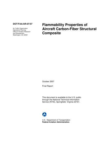
Slide 1AVIONICS FUNDAMENTALSNOTE: This course covers the theory of the general operation, not model specific Avionics equipment. This course does notsupersede Original Equipment Manufactures instructions or operation. It is for training purposes only!!Upon completion of this course the student will be able to state the purpose and function for the following: Theory of Flight and Control Surfaces Electrical Safety Electrical Power Sources Altimetry and the Atmosphere Pitot Static Systems Servo Motors and Tach Rate Generators Inertial Reference Compass Systems Inertial Navigation/Reference Systems Automatic Direction Finder (ADF) Global Positioning System (GPS) Very High Frequency Omni-Range (VOR) Instrument Landing System (ILS) Air Traffic Control System (ATC) Distance Measuring Equipment (DME) Marker Beacon System (MB) Radio Altimeter Principle (RA) Air Data Systems (ADS) Ground Proximity Warning System (GPWS)
Flight Directors Auto Pilot Autopilot Yaw Damper- Rudder Channel Automatic Flight Guidance Systems Area Navigation (RNAV) Radio Altimeter Weather Radar Traffic Collision Avoidance System (TCAS)
Slide 2AIRCRAFT AVIONICSAIRCRAFT AVIONICSDuring the Wright brothers first flight they had no idea of speed, altitude, the direction theaircraft was flying. They also did not know fuel consumption, engine temperature, prop RPM ex.So basically they had no aircraft system, just flight controls.The term avionics was not in general use until the early 1970s. Up to this point instruments, radios,radar, fuel systems, engine controls and radio navigation had individual mechanical systems.In the 1970s era, avionics was born, driven by military modernization rather than civil development.Military aircraft had become flying computer platforms, and making large amounts of electronic equipmentwork together had become the new norm.Today, avionics as used in civil aircraft. The glass cockpit (TV type screens instead of individualinstruments ) Under the floor and nose of an aircraft is a major location for avionic equipment, includingcontrol, monitoring, communication, navigation, weather, and anti-collision systems. The majority ofaircraft avionics are using 14 or 28 volt DC electrical systems.There are several major vendors of flight avionics just to list a few, including Honeywell Bendix King,Baker Electronics, Allied Signal, Rock Well Collins, Thales Group Garmin, and Ayidyne Corporation ex.
Slide 3MODERN AIRCRAFTAVIONICSMODERN AIRCRAFT AVIONICS:The pilot programs the Flight Management System (FMS) for destination and the computers take over after take-off.The Avionics system in today’s Aircraft are based on the computer hardware and software interface. The Modern Avionics systemof today enhances flight safety and pilot comfort:Improves pilot situational awareness,Complete man-machine interface,Better crew coordination,Reduced flight crew workload,It keeps the pilot and co-pilot well informed.The Navigation system includes the navigation with:Two or more Air Data Systems (ADS),Two Radar Altimeter (RA),One Weather Radar System (WX),One Enhance Ground Proximity Warning System (EGPWS),One Traffic Collision Avoidance System (TCAS),The Indicating-Recording system provides:Visual and Aural Warnings,
Crew Alerting Systems (CAS)Data Recording,Data Collecting,Data Calculating for Different Systems.Flight Data recorderWhen Auto Pilot is engaged, the primary flight controls computers controls the aircraft through the flight control surfaces thatfollow Automatic Flight Control System commands.The auto flight system includes the computer and servo systems that automatically control the flight of the aircraft. These systemsuse data from different sources and feedback circuits to control the direction, heading, attitude, and speed of the aircraft.The auto flight system has the subsystems that follow:Automatic Flight Control System (AFCS),Auto throttle.The Automatic Flight Control System (AFCS) controls the aircraft heading and altitude automatically and provides systemindications. The Navigation system management is provided by:Two or more Primary Display Unit (PDU),One or two Head Up Guidance System (HGS) (optional).Autopilot (AP),Yaw Damper (YD),Mach trim,Flight Director (FD).The aircraft basically controls the Flight envelope to protect itself during flight.Auto Throttle The auto throttle supplies automatic speed control, this is similar to your Cruise Control on your car. This systemsets the speed and fuel management with a minimum of flight crew inputs.The Communications system performs the radio transmissions in an aircraft, between pilot ,co-pilot, other aircraft, and groundstations. The antennas for the systems are installed on the fuselage and vertical stabilizer of most aircraft.The communications system include the avionics equipment used for:Voice and data communications, cockpit audio and monitoring.The Electrical system architecture is built upon the main parts that follows:The Electrical System provides:DC electrical power,AC electrical power,Batteries that store electrical powerDistribution system (Buses) for electric power distribution to different systems in the aircraft,Protect aircraft wiring from overheating during fault problems,Breakers so power source failures can be reset,Allow the flight crew to manually shut down systems,Provide APU starting and electrical power capability,Allow connection to an external Ground Power Unit (GPU).
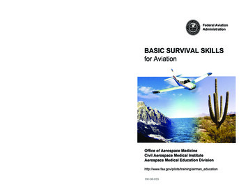
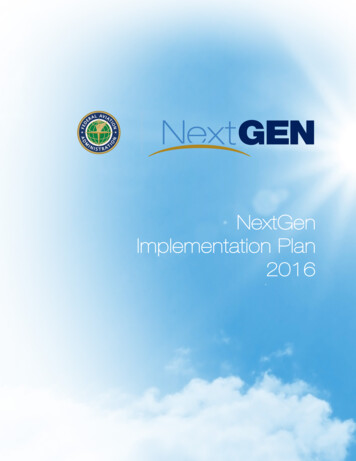
Slide 4THEORY OF FLIGHTTHEORY OF FLIGHTTo achieve flight certain 4 forces have to be put in balance. First the force of GRAVITY holds the aircraft on the ground. Secondly DRAG prevents forward motion. Engines are installed to produce THRUST(forward motion) to overcome drag and create forward motion. (Air Speed) This is the force which is (Air Speed) overcomes drag. Once forward motion isachieved the wing can begin to produce LIFT, the force that overcomes gravity.
Slide 5THEORY OF FLIGHTTHEORY OF FLIGHTFor the Aircraft to fly there are certain forces to overcome: First the force is GRAVITY that holds the aircraft on the ground has to be overcome.Lift will overcome gravity. The Wing creates lift by using forward motion. LIFT is produced by air flowing over the curved upper wing surface at a velocity higherthan airflow on the lower surface. Increased airflow causes an increase in velocity anda subsequent drop in air pressure. (Vacuum effect) Airflow is achieved by maintainingforward movement. (Air Speed) The larger the wing area the thicker the wing require less air flow at lower air speed tomaintain lift. The thin wing requires more airspeed for more airflow to maintain lift. In Flight you must have Flight Control, which is controlled by Flight Surfaces. The Pilot can control Flight Surfaces or the Avionics Systems.
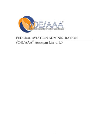
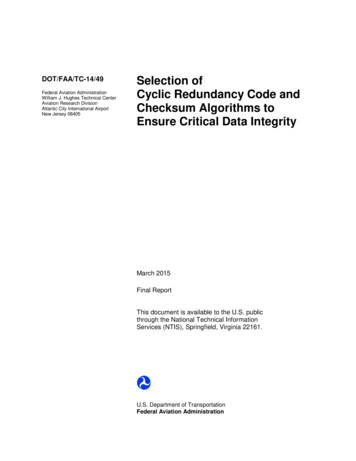
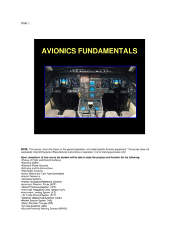
Slide 6FLIGHT LELEVATORCONTROLSPITCHFlight Control SurfacesYaw: Is Controlled By The RudderFoot pedals are connected by means of push-pull tubes and or Cables and hydraulics tothe rudder of the tail section. The rudder is the vertical part of the tail that can movefrom side to side. (left to right) Pushing on the left rudder pedal moves the rudder to the left, causing the nose of theairplane to move to the left. Pushing on the right rudder pedal moves the rudder to the right, causing the nose ofthe airplane to move to the right.
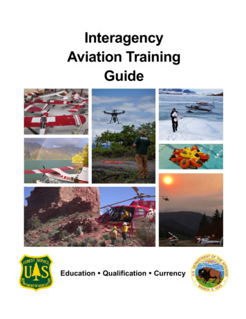
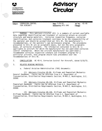
Slide 7FLIGHT CONTROLSURFACESTheory of Flight and Control SurfacesROLL: Is Controlled By The Ailerons.The control wheel (yoke) is connected by means of push-pull tubes and or Cables andhydraulics to the wings' ailerons. By turning the left or right, the pilot can change thepositions of the ailerons. When the control wheel is turned to the right, the right aileron goes up and the leftaileron goes down, rolling the airplane to the right. Turned to the left, the right aileron goes down and the left aileron goes up, rolling theairplane to the left.
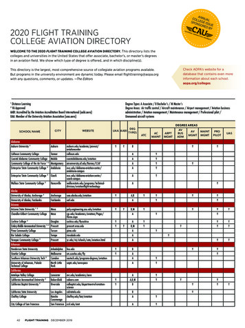
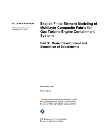
Slide 8FLIGHT CONTROL SURFACESTheory of Flight Control SurfacesPITCH: Is Controlled By The Elevator. nose up, nose downThe control column (Yoke) is connected by means of push-pull tubes and or Cables andhydraulics to the tail section's elevators. By moving the yoke, the pilot can change theposition of the elevators. Pushing the control column forward, the elevators move down, pitching the tail of theairplane up and the nose down, rolling the airplane down. Pulling the control column back makes the elevators move up, pitching the tail of theairplane down an the nose up, rolling the airplane upwards.
Slide 9FLIGHT CONTROL SURFACESFlight Control SurfacesThese Flight Control Surfaces can provide control for the following: Turns Nose up, Nose Down for climbing or descending.The first 2 bullets are usually controlled by Avionics systems after the pilot programs thetrip into the system prior to flight. (Auto Pilot) Height above the earth (Altitude) 0 is considered Sea Level. Compass Headings: (Direction the aircraft is to fly) They also provide control for Take-off and Landings.( Usually controlled by thePilots) The following slides we will go into Avionics Fundamentals.
Slide 10ALTIMETRY AND THEATMOSPHEREAltimetry and the AtmosphereAltimetry is the height above sea level. (The measurement of altitude)Atmosphere is the mixture of gases (Air) that surrounds the Earth. Atmospheric Pressure is the force per unit area that is applied perpendicularly to asurface by the surrounding gas. It is determined by the Earths gravitational force incombination with the total mass of a column of air above a location. (Barometricpressure) The pressure is greater at sea level than at 45,000 feet.
Slide 11ALTITUDE DEFINITIONSALTITUDE DEFINITIONS Indicated altitude is read directly from the altimeter when set to current barometricpressure. Earths Pressure altitude is read from the altimeter when set to the standardbarometric pressure of 29.92 in. Hg. True altitude is the exact height above mean Sea level. Absolute altitude is the l height above the Terrain surface.
Slide 12BASIC AVIONICSAVIONICS: Avionics is defined as "aviation electronics". It consist of electronic systems for use on aircraft, comprising communication,navigation with display and management of multiple systems. It also includes multiple variants of systems that are used on aircraft to meet theirindividual roles, these can be simple avionics or more complex computer systems inultra modern aircraft. Today's aircraft being built using more complicated avionics systems than the aircraftbuilt in the previous 50 years. Usually there are 2 sets of instruments 1 set each side of the aircraft, Right hand sidefor Co-Pilot, Left Hand side for Pilot. The FAA requires that avionics systems be redundant in case of failure of one system,there is a back up system.
The following information will help you have better basic understanding of the how, andwhy of Avionics Instruments.
Slide 13ELECTRICAL SAFETYELECTRICAL SAFETYRemember the life you save could be yours!!!Before working on any Avionics systems/Wiring ask your self the following: Is Aircraft power On or Off? Any Batteries connected? Are switches and breakers On or Off? Are there breakers locked out tagged out for other maintenance? Can I safely apply power to the Aircraft? Do I have the proper Approved Aircraft Data for the job I am doing? I am using correct Electro Static Discharge (ESD) procedures?
Slide 14ELECTRICAL POWERSOURCESELECTRICAL POWER SOURCES FOR THE AVIONICS SYSTEMSAircraft Electrical Power can come from several sources.This is the list of Power sources that can be used to put Power on the Aircraft AvionicsSystems. Auxiliary Power Unit (APU) Aircraft Batteries (Short duration only) Ground Power Unit (GPU) Turbine Engines Generators or Alternators
Slide 15PITOT STATIC SYSTEMSPITOT STATIC SYSTEMSAircraft atmosphere pressure changes as it climbs, descends, accelerates ordecelerates. The pitot-static system is sensitive to airspeed, altitude, and rates of altitude changethus provides the pressure information displayed on instrumentation. Pitot-static system is a system of Atmospheric Pressure -sensitive instruments that ismost often used in aviation to determine: an aircraft's airspeed , Mach number, Vertical Speed Indicator altitude. A pitot-static system generally consists of a 2 pitot tubes, one on each side of theaircraft , and 2 static ports one on each side of the aircraft and the instruments. These type systems must be Maintained in accordance with applicable regulations 91-411 / 91-413 (per FAR 43 Appendix F, forUS registered A/C) Inspected per FAR 91.409, for US registered A/C), and (JAR 145,and JAR1.15.4.3 for European A/C)
(There are FAA regulations governing scratches and damage to the Static plate andpitot Tubes.)
Slide 16PITOT PRESSUREPITOT PRESSUREPitot-static system is a system of Atmospheric Pressure -sensitive instruments that ismost often used in aviation to determine:PITOT PRESSURE DEFINITIONPITOT TUBE DEFINITION The pitot pressure is obtained from the PITOT TUBE. The pitot pressure is a measure of ram air pressure (the dynamic air pressurecreated by air speed or the air ramming into the tube), which, under ideal conditions, isequal to stagnation pressure. The pitot tube is most often located on the wing or front section of an aircraft, facingforward, where its opening is exposed to the movement of air. By placing the pitot tube in these locations, the ram air pressure is more accuratelymeasured since it will be less distorted by the aircraft's structure. When airspeedincreases, the ram air pressure is increased, which can be translated by airspeed
indicator. Airspeed, Mach number, Altitude. A pitot-static system generally consists of a pitot tube, a static port, and theinstruments.
Slide 17BASIC AIRSPEEDINSTRUMENTBASIC AIRSPEED INSTRUMENT The airspeed indicator uses the ram pressure from the pitot tube. The airspeedindicator is connected to both t
AVIONICS FUNDAMENTALS NOTE: This course covers the theory of the general operation, not model specific Avionics equipment. This course does not supersede Original Equipment Manufactures instructions or operation. It is for training purposes only!! Upon completion of this course the student will be able to state the purpose and function for the following: Theory of Flight and Control .