Transcription
DOT/FAA/AR-04/40,P3Office of Aviation ResearchWashington, D.C. 20591Explicit Finite Element Modeling ofMultilayer Composite Fabric forGas Turbine Engine ContainmentSystemsPart 3: Model Development andSimulation of ExperimentsNovember 2004Final ReportThis document is available to the U.S. publicthrough the National Technical InformationService (NTIS), Springfield, Virginia 22161.U.S. Department of TransportationFederal Aviation Administration
NOTICEThis document is disseminated under the sponsorship of the U.S.Department of Transportation in the interest of information exchange. TheUnited States Government assumes no liability for the contents or usethereof. The United States Government does not endorse products ormanufacturers. Trade or manufacturer's names appear herein solelybecause they are considered essential to the objective of this report. Thisdocument does not constitute FAA certification policy. Consult your localFAA aircraft certification office as to its use.This report is available at the Federal Aviation Administration William J.Hughes Technical Center's Full-Text Technical Reports page:actlibrary.tc.faa.gov in Adobe Acrobat portable document format (PDF).
Technical Report Documentation Page1. Report No.2. Government AccessionNo.3. Recipient's Catalog No.DOT/FAA/AR-04/40,P34. Title and Subtitle5. Report DateEXPLICIT FINITE ELEMENT MODELING OF MULTILAYER COMPOSITEFABRIC FOR GAS TURBINE ENGINE CONTAINMENT SYSTEMSPART 3: MODEL DEVELOPMENT AND SIMULATION OF EXPERIMENTSNovember 20047. Author(s)8. Performing Organization Report No.6. Performing Organization CodeJeffrey Simmons, David Erlich, and Donald Shockey9. Performing Organization Name and Address10. Work Unit No. (TRAIS)SRI International33 Ravenswood AvenueMenlo Park, CA 9402511. Contract or Grant No.12. Sponsoring Agency Name and Address13. Type of Report and Period Covered01-C-AW-ASUFinal Report8/2001 – 5/2003U.S. Department of TransportationFederal Aviation AdministrationOffice of Aviation ResearchWashington, DC 2059114. Sponsoring Agency CodeANE-100, ANM-10015. Supplementary NotesThe FAA William J. Hughes Technical Center COTR was Donald Altobelli.16. AbstractUnder the Federal Aviation Administration Airworthiness Assurance Center of Excellence and with support from the AircraftCatastrophic Failure Prevention Program, SRI International collaborated with Arizona State University; Honeywell Engines, Systemsand Services; and the National Aeronautics and Space Administration Glenn Research Center to develop a computational model fordesigning and evaluating ballistic fabric containment structures. This report describes the model and compares the results of staticand impact penetration tests with the results of computational simulations.17. Key Words18. Distribution StatementFan containment, Jet engine, Composite fabric,Ballistic impact, Zylon, KevlarThis document is available to the public through the National TechnicalInformation Service (NTIS) Springfield, Virginia 22161.19. Security Classif. (of this report)20. Security Classif. (of this page)UnclassifiedForm DOT F1700.721. No. of PagesUnclassified(8-72)Reproduction of completed page authorized5922. Price
TABLE OF CONTENTSPageEXECUTIVE ndFINITE ELEMENT ANALYSIS22.12.2BackgroundThe Finite Element Model for Ballistic 2.92334566782.32.42.52.62.72.82.9Fabric Response in Uniaxial TensionFabric Response Under Cyclic LoadingModel BasicsDamage MechanicsRate Dependence for FailureModel ResponseOff-Diagonal and Shear ResponseMultiple PliesFabric SlackAnalysis Considerations82.3.1 Mesh Size2.3.2 Contact Parameters88Approach for Model DevelopmentSingle-Ply, Quasi-Static Uniaxial TestsAnalysis of ASU Static Ring Tests88102.6.1 Kevlar Ring2.6.2 Zylon Ring1012NASA Tests132.7.1 Ballistic Test Simulation Results2.7.2 Computational Results: Comparing With Data2.7.3 Kevlar Tests2.7.4 Zylon Tests14151617Discussion of ResultsOther Items Worthy of Consideration and Further Investigation1818iii
3.4.SWATH PUSH TESTS193.13.23.33.420222426Swath Push Test ResultsMultiple-Ply Swath Push Test ResultsUnloading BehaviorSummaryREFERENCES26APPENDICESA—User’s GuideB—SRI Summary Report, March 2002LIST OF FIGURESFigurePage1Response of Kevlar Fabric to Uniaxial Tension Loading32Cyclic Response of Fabric to Uniaxial Tension33Stress-Strain Curve for a Fiber44Fiber Damage as a Function of Strain55Uniaxial Stress-Strain Curve for Ballistic Fabric Model66Static Ring Test Results77Fabric Model for Uniaxial Tests98Finite Element Model of Static Ring Test119Calculated Force Displacement for Static Ring Test With Kevlar1110Calculated Response of Single-Layer Zylon1211Calculated Force Displacement for Static Ring Test With Zylon1312Test Setup for the NASA Ballistic Tests1313Experiment and Simulation Results for NASA Test LG408, Eight-Ply Target ofZylon15iv
14Dimensionless Plot of V50 Results of Fabric Armor Systems1615Simulation Results for Ballistic Tests on Kevlar Fabric1716Simulation Results for Ballistic Tests on Zylon Targets1717Load-Stroke Response of Kevlar Swaths2118Stress-Strain Response of Kevlar Swaths2119Load-Stroke Response of Zylon Swaths2220Stress-Strain Response of Zylon Swaths2221Averaging Two Kevlar Plies Displaced by a Strain of 0.012322Strain Offset Model Results for Two-, Four-, and Eight-Ply Kevlar2423Cyclic Unloading Response of Kevlar Swaths2524Cyclic Unloading Response of Zylon Swaths25LIST OF TABLESTable123456PageProperties of Zylon and Kevlar FabricsConstants for Kevlar and ZylonRing Test Force and PlyBallistic Test Results for KevlarBallistic Test Results for ZylonSummary of Swath Test Data on 1.5-in.-Wide Baseline Fabric Swathsv21012141420
LIST OF ACRONYMSACFPPASUFAALSTCNASA GRCSRIAircraft Catastrophic Failure Prevention ProgramArizona State UniversityFederal Aviation AdministrationLivermore Software Technology CompanyNational Aeronautics and Space Administration Glenn Research CenterSRI Internationalvi
EXECUTIVE SUMMARYModeling a multilayer fabric composite for engine containment systems during a fan blade-outevent has been a challenging task. Nonlinear transient (explicit) finite element (FE) analysis hasthe greatest potential of any numerical approach available to industry for analysis of theseevents. Significant research is still required to overcome difficulties with numerical stability,material modeling (pre- and postfailure), and standardizing model methods to achieve accuratesimulation of the complex interactions between individual components during these high-speedevents. The primary focus of this research was to develop the methodology for testing,modeling, and analyzing a typical fan blade-out event in a multilayer fiber fabric compositecontainment system. ABAQUS FE code was used to verify the basic material model (prefailurestate) developed through laboratory testing. LS-DYNA was the primary modeling tool used inthe explicit FE analysis of ballistic events.During the Fourth Federal Aviation Administration (FAA) Uncontained Engine DebrisCharacterization Modeling and Mitigation Workshop (held in May 2000 at SRI International,Menlo Park, CA), a representative of Honeywell Engines, Systems & Services presented thecapability of modeling complicated engine hub-burst and fan blade-out events. Predicting mostof the event with high confidence was shown. At the same time, SRI presented their efforts onmodeling the material characteristics within LS-DYNA and developing a new composite fibermaterial called Zylon that appeared to be stronger, lighter, and more temperature-resistant thanKevlar . Both parties showed interest in each other’s work, and both agreed they could benefitfrom each other if collaborative mechanisms could be arranged. After the workshop, Honeywelland SRI contacted each other and began talks of a joint project. The FAA, the NationalAeronautics and Space Administration (NASA) Glenn Research Center (GRC), and ArizonaState University (ASU) were later invited into the discussion, resulting in this FAA-fundedresearch under the Aircraft Catastrophic Prevention Program and the Airworthiness AssuranceCenter of Excellence Program.The goal of this research, was to use the technical strengths of Honeywell, SRI, NASA GRC, andASU for developing a robust explicit FE analysis modeling methodology for the purposesmentioned above. Since the development of an experimental set of data to support thecalibration of the FE models is essential, various experimental methods to measure material andstructural response of the fabrics were conducted. NASA GRC, under the NASA AviationSafety Program, conducted a series of fabric engine containment ring tests that were used formodeling in this program.Each member of the team took a leadership role and developed a comprehensive reportdescribing the details of the research task and the findings. The complete FAA report iscomprised of the following four separate reports (parts 1 through 4). Part 1: Static Tests and Modeling by Arizona State University Department of CivilEngineering Part 2: Ballistic Testing by NASA Glenn Research Centervii
Part 3: Material Model Development and Simulation of Experiments by SRIInternational Part 4: Model Simulation for Ballistic Tests, Engine Fan Blade-Out, and Generic Engineby Honeywell Engines, Systems & ServicesSRI’s role was to produce a FE model for multilayer fabric, implement the model into LSDYNA, determine material properties for Zylon and Kevlar from static tests, and evaluate themodel by simulating fragment impact experiments. This report describes the model developmentand the results of the computational simulations.The form of the fabric model and the material parameters were based on observations andmeasurements from uniaxial and cyclic load experiments on single plies of fabric performed atASU and SRI. Multiple fabric plies were modeled with one shell element, whose thickness wasproportional to the number of plies. A single set of material constants was determined for eachfabric.Additional experiments were performed in which a fragment simulator penetrated multiple layersof fabric wrapped around a steel ring, a configuration representative of an engine containmentring. Quasi-static tests were performed at ASU, and ballistic tests were performed at NASAGRC. The model was evaluated by simulating these tests.Overall, the simulation results agreed well with test results. For the quasi-static tests on Kevlar,the calculated values for peak load and strain to failure were close to the measured averagevalues. For Zylon, the calculated peak load was about 15% below the measured average for thequasi-static tests.For the ballistic tests on Kevlar, the model closely predicted the energy absorbed for the 4-, 8-,16- and 24-ply tests, but underpredicted the energy absorbed for the 1- and 2-ply tests. ForZylon, the model predicted the energy-absorbed values within the test data scatter for 4, 8, and16 layers, but underpredicted the energy absorbed for 24 plies.The results showed that the choice of analysis parameters and solution algorithms (particularlythe choice of slideline parameters) has a big effect on the energy absorbed that was calculated inballistic tests. Future work will need to determine the sensitivity of the model to theseparameters. An improved treatment of rate effects is also needed. In addition, a procedure forusing multiple layers of shell elements to model many fabric plies will facilitate designcomputations.viii
1. INTRODUCTION.1.1 PURPOSE.This research effort was undertaken as a direct result of discussions from the Fourth FederalAviation Administration (FAA) Uncontained Debris Characterization Modeling and MitigationWorkshop (held in May 2000 at SRI International). A teaming effort between government,academia, and industry was seen as an excellent opportunity to transition fabric modeling andtesting research, that was being sponsored by the FAA Aircraft Catastrophic Failure PreventionProgram (ACFPP), into commercial aircraft.1.2 BACKGROUND.Over the last 7 years, under the sponsorship of the ACFPP of the FAA, SRI conducted a researchprogram aimed at enhancing the safety of civilian air travel by reducing the likelihood of acatastrophic accident in the event of an uncontained engine failure.SRI began by reviewing advanced military armor technology to identify materials, armorstructures, and projectile defeat concepts that could be used in designing barriers to turbineengine fragments for commercial aircraft. Experiments and computations were then performedto evaluate these findings. The work identified an advanced material with significantly betterresistance to fragment penetration, demonstrated barrier structures that can protect against smallto medium turbine engine blade fragments at a tenth of the weight of aluminum barriers, anddeveloped a computational capability for designing fragment barriers. Full-scale ballisticexperiments on fuselage sections with advanced polymer fabric barriers confirmed the ballisticeffectiveness of lightweight fabric barriers.The results attracted the attention of the commercial aircraft industry. Under continuedsponsorship by the ACFPP and new grants from the Airworthiness Assurance Center ofExcellence (AACE), SRI worked with an aircraft engine manufacturer and an airframemanufacturer to transfer this technology to industry and to address specific needs of the aircraftindustry. This project with Arizona State University (ASU), Honeywell Engines, Systems &Services, and National Aeronautics and Space Administration (NASA) Glenn Research Center(GRC) aimed at adapting the SRI fabric model to address fragment containment issues, whileanother project with the University of California at Berkeley and The Boeing Companyevaluated the effectiveness of multilayer Zylon fabric in protecting fuselage structures fromuncontained debris.SRI’s effort in the ASU, Honeywell, and NASA GRC program is presented here. The objectiveof this research was to develop and demonstrate a computational model of ballistic response offabrics under engine containment conditions. The desired end product was a computationalcapability for designing multilayer fabric engine containment structures for commercial transportaircraft. SRI’s part was (1) to perform static laboratory experiments (swath tests) to measureresponse of multilayer fabrics to slow penetration, (2) to use the data and observations along withring test data from ASU and ballistic data from NASA GRC to develop a computational modelof fabric response, and (3) to evaluate the model by simulating the experiments and comparing1
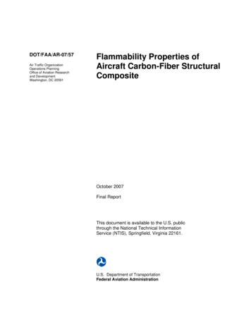
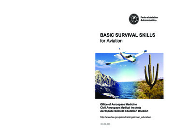
computed and observed behavior. The procedures and results of this effort are presented in thefollowing sections.2. FINITE ELEMENT ANALYSIS.2.1 BACKGROUND.A computational model is being developed that can be used as a design tool for choosing orevaluating parameters for fragment barriers containing ballistic fabric. The design model,implemented into the LS-DYNA finite element code, uses shell elements with an orthotropiccontinuum formulation to model the fabric. Because calculations run relatively quickly (about15 minutes using a four-processor Pentium III Linux cluster for a 20,000 element simulation of agas gun experiment), the model allows design parameters to be varied and evaluated. Theresponse of barrier characteristics, such as size of fabric, gripping conditions, number of fabricplies, and yarn pitch, can be simulated as well as the size, orientation, and velocity of a fragment.Thus, the model is intended to be useful in designing and certifying fragment barriers, i.e., indetermining how many plies of woven fabric are needed to stop a given fragment threat and incomputing the loads applied to the supporting structure. The physical properties of the ballisticfabrics used in this program, Zylon AS and Kevlar 49 , are listed in table 1.TABLE 1. PROPERTIES OF ZYLON AND KEVLAR FABRICSTrade NameMaterialVolume Density (from manufacturer)Yarn Denier—As-OrderedYarn Denier—MeasuredYarn Linear Density—MeasuredYarn Cross-Sectional AreaYarn CountFabric Ply thickness (approx.)Fabric Areal Density—Measured3(g/cm )(g/9 km)(g/9 km)(mg/cm)(cm2 x 10-4)(in2 x 10-5)(yarns/cm)(in.)(mm)(g/cm2)(lb/ft2)Zylon ASPolybenzobisoxazole1.545005000.5563.615.5935 x 350.0080.210.015750.0323Kevlar 49P-Aramid1.44142014901.65611.5017.8217 x 170.0110.280.022750.04662.2 THE FINITE ELEMENT MODEL FOR BALLISTIC FABRIC.2.2.1 Fabric Response in Uniaxial Tension.The response of a single ply of Kevlar fabric tested in uniaxial tension, shown in figure 1, isrepresentative of ballistic fabric, and has the following features: (1) a low initial modulus due tostraightening of yarn crimp, followed by (2) a linear response up to initial damage (breaking of2
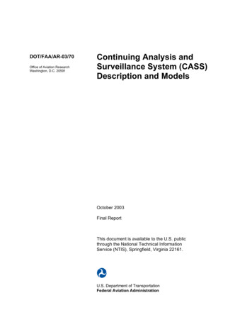
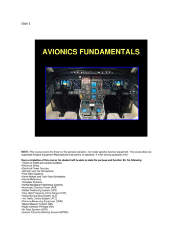
fibers), which results in (3) a reduced and nonlinear modulus up to a peak loading, followed by(4) a postpeak drop in strength with increased strain.FIGURE 1. RESPONSE OF KEVLAR FABRIC TO UNIAXIAL TENSION LOADING2.2.2 Fabric Response Under Cyclic Loading.The cyclic response of ballistic fabric in tension is shown in figure 2. Zylon (figure 2(a)) andKevlar (figure 2(b)) show a similar response. Unloading and subsequent reloading of the fabricfollow a single curve that is nearly linear with a modulus that is stiffer than the original loadingmodulus for unloading before the peak stress is reached. As the fabric acquires damage, theunloading modulus decreases.(a) Zylon(b) KevlarFIGURE 2. CYCLIC RESPONSE OF FABRIC TO UNIAXIAL TENSION2.2.3 Model Basics.The ballistic fabric model being developed is an orthotropic model with a stress-strain responsefor each of the two yarn (local x and y) directions. The stress-strain responses in the twodirections are assumed to be uncoupled, that is, the interaction between the orthogonal yarns dueto the weave pattern is ignored. However, the failure response is coupled.3
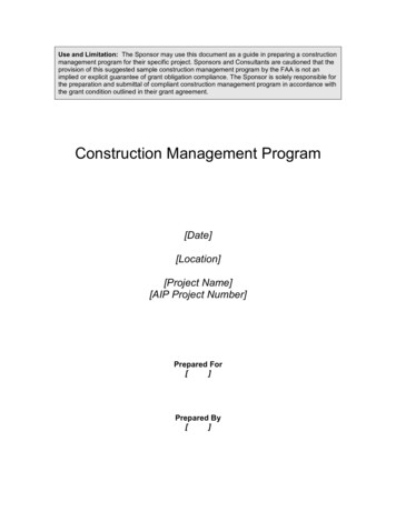
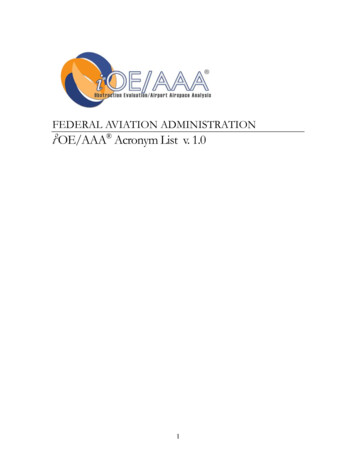
2.2.4 Damage Mechanics.The approach to modeling the response of ballistic fabric was to combine a mechanisticconstitutive law for the fibers in the yarns in each direction with a damage law that governs fiberbreakage.Figure 3 shows the stress-strain curve for a fiber in a yarn for cyclic loading. Cyclic loading isimportant because it gives data in the amount of fabric damage that has been experienced in theloading process. Initially, the fiber has a low modulus corresponding to the stress required tostraighten the crimp in the yarn. Once the fiber is straightened, the response in loading is linearelastic up to a peak stress at which failure occurs, i.e., the fibers begin to break. On unloadingand subsequent reloading, the fiber is linear elastic with a modulus twice as stiff as the originalelastic modulus. It is believed that the change in modulus on unloading and subsequenthysteresis corresponds to the rearrangement of yarns in the fabric. These effects may depend onfabric weave or yarn twist, but this dependence was not investigated. In compression, the modelfiber has a very small (but nonzero) modulus.FIGURE 3. STRESS-STRAIN CURVE FOR A FIBERTo model damage and failure for the fabric, the mechanism of tensile failure of the fibers in theyarn was considered. Each yarn is typically made up of 200 to 250 fibers. As shown in figure 3,the fibers are assumed to be elastic until they break in tension. For the continuum model, theaxial stress in the fabric, σ a , is assumed to be the stress from the strain in the unbroken yarns.Under monotonic loading, the axial stress is given byσ a Eε a (1 d σ )4(1)
where, E is the fiber axial modulus, d σ is the fraction of broken yarns (which varies from zero toone), and ε a is the effective axial strain defined as the total axial strain, ε a , minus the crimpstrain, ε cr . For a dynamic analysis, the rate of axial stress, σ& a , is given byσ& a E (1 d σ )ε &a Ed&σ ε a(2)It is assumed that the fibers do not all break at the same time,
Aeronautics and Space Administration (NASA) Glenn Research Center (GRC), and Arizona State University (ASU) were later invited into the discussion, resulting in this FAA-funded research under the Aircraft Catastrophic Prevention Program and the Airworthiness Assurance Center of Excellence Program.