Transcription
DOT/FAA/AR-07/57Air Traffic OrganizationOperations PlanningOffice of Aviation Researchand DevelopmentWashington, DC 20591Flammability Properties ofAircraft Carbon-Fiber StructuralCompositeOctober 2007Final ReportThis document is available to the U.S. publicthrough the National Technical InformationService (NTIS), Springfield, Virginia 22161.U.S. Department of TransportationFederal Aviation Administration
NOTICEThis document is disseminated under the sponsorship of the U.S.Department of Transportation in the interest of information exchange. TheUnited States Government assumes no liability for the contents or usethereof. The United States Government does not endorse products ormanufacturers. Trade or manufacturer's names appear herein solelybecause they are considered essential to the objective of this report. Thisdocument does not constitute FAA certification policy. Consult your localFAA aircraft certification office as to its use.This report is available at the Federal Aviation Administration William J.Hughes Technical Center's Full-Text Technical Reports page:actlibrary.tc.faa.gov in Adobe Acrobat portable document format (PDF).
Technical Report Documentation Page1. Report No.2. Government Accession No.3. Recipient's Catalog No.DOT/FAA/AR-07/574. Title and Subtitle5. Report DateFLAMMABILITY PROPERTIES OF AIRCRAFT CARBON-FIBERSTRUCTURAL COMPOSITEOctober 20077. Author(s)8. Performing Organization Report No.6. Performing Organization CodeJames G. Quintiere*, Richard N. Walters, and Sean Crowley9. Performing Organization Name and Address10. Work Unit No. (TRAIS)Federal Aviation AdministrationWilliam J. Hughes Technical Center*Dept of Fire Protection EngineeringAirport & AircraftUniversity of MarylandSafety Research & Development Division OISI Glenn L. Martin Hall (Bldg. 088)Fire Safety SectionCollege Park, MD 20742Atlantic City International Airport, NJ 0840512. Sponsoring Agency Name and Address11. Contract or Grant No.13. Type of Report and Period CoveredU.S. Department of TransportationFederal Aviation AdministrationAir Traffic Organization Operations PlanningOffice of Aviation Research and DevelopmentWashington, DC 20591Final Report14. Sponsoring Agency CodeANM-11515. Supplementary Notes16. AbstractThis study investigated the flammability of a carbon-fiber composite material for use in aircraft structures. In particular, itconsidered a composite material manufactured by Toray Composites (America) to Boeing Material Specification 8-276. Theobjective was to establish a complete set of properties pertaining to the heating and burning characteristics of these materials infires. Several apparatuses were used, including the cone calorimeter, microscale combustion calorimeter, thermogravimetricanalyzer, differential scanning calorimeter, and a flame spread rig to promote spread with preheating by radiation. An attemptwas made to measure the thermal conductivity of the composite over a range of temperatures through its decomposition, but theheat losses from the apparatus likely caused an overestimate in the measurement. Data from standard tests were also reported forthe Ohio State University calorimeter and the smoke density chamber.The material burns in a manner similar to a charring material, in that the carbon fibers comprise most of its mass. The compositeburns primarily from the vaporization of its resin. It can ignite with a pilot flame after preheating at a low heat flux. When itburns, the resin vapor is forced out of the fiber pores, and pressure causes the material to swell to over twice its volume. In mostall cases studied, the composite maintained its rigidity, but its structural strength was not examined after degradation. Thematerial appears to maintain homogeneity in swelling. The fibers create an insulating, char-like structure that causes a reductionin the internal heating, and consequently, the burning rate drops in time. As the burning rate drops, extinction can naturally occurdue to insufficient heating. As is common of charring materials, external heat flux is required to sustain burning and flamespread. It should be noted that the carbon fiber can also oxidize under high-temperature conditions, and this was observed even atlow heat fluxes. Furthermore, the properties in this report pertain primarily to the characteristics of the resin material, as thecarbon fibers are essentially inert.The data in this report can be used for modeling and explaining the fire behavior of the composite in fire scenarios associated withaircraft operations.17. Key Words18. Distribution StatementCarbon fiber, Composite, Flame spread, Heat releaseThis document is available to the U.S. public through theNational Technical Information Service (NTIS) Springfield,Virginia 22161.19. Security Classif. (of this report)UnclassifiedForm DOT F1700.7 (8-72)20. Security Classif. (of this page)UnclassifiedReproduction of completed page authorized21. No. of Pages4322. Price
ACKNOWLEDGEMENTSJ.G. Quintiere is indebted to Gus Sarkos and Dick Hill for their support and motivation for thisstudy of carbon-fiber composite material for aircraft construction. Discussions with RichardLyon on the approach and interpretation of the data have been rewarding and critical to the fullunderstanding of the composite characteristics. Also, the author is grateful to Dr. Lyon forextending the hospitality of the facilities and resources of his group for this study. His staff,Sean Crowley and Richard Walters, are co-authors of this report, and their contributions aregreatly appreciated.iii/iv
TABLE OF CONTENTSPageEXECUTIVE SUMMARYix1.INTRODUCTION12.EXPERIMENTAL MEASUREMENTS22.12.22.32.42.52.62.72.8Thermal ConductivityThermodynamic PropertiesKinetics of DegradationIgnitionBurningYields and Morphology of BurningYields of Incomplete Combustion ProductsFlame Spread3468111925283.SUMMARY OF RESULTS314.CONCLUSIONS335.REFERENCES33v
LIST OF c20d20e20f20g20h212223242526272829303132PageToray Carbon-Fiber Composite: Smooth Face, Edge, and Rough Face, Left to RightConduction Apparatus: Heater Plate in Specimen Sandwich With Edge InsulationComposite Thermal Conductivity Versus TemperatureThe DSC Results, Specific Heat, and Heat of DecompositionMicroscale Combustion Calorimeter ResultsArrhenius Plot to Determine Kinetic Parameters of Thermal DecompositionThe TGA Results and Comparison to First-Order ModelTime to Ignite: Piloted and AutoThermal Response Parameter Values From Ignition Delay ExperimentsThermally Thick Theory Compared to Data for Piloted IgnitionHeat Release in OSU CalorimeterHeat Release Rate per Unit Area at Fluxes From 25 to 100 kW/m2Average Peak HRR Over Burning RangeHeat of Combustion Over Range of BurningThe HRR During the Critical Burning Series With IgniterTotal Energy Released in BurningBurning Rate of Carbon Fibers in SmolderingSurface Temperatures of Carbon Fiber SmolderingVertical Burning in the OSU ApparatusAfter Burning Front and Back, 8.2 kW/m2After Burning Front and Back, 12.3 kW/m2After Burning Front and Back, 14.7 kW/m2After Heating Front and Back, 17.5 kW/m2After Burning Front and Back, 18.7 kW/m2After Burning Front and Back, 40.0 kW/m2After Burning Front and Back, 60.0 kW/m2After Burning Front and Back, 85 kW/m2Thickness Increase on BurningMorphology of Composite After BurningCross Section of the 40 kW/m2 Heated CompositeYield of CO for Flaming ConditionsYield of Smoke for Flaming ConditionsThe Ds for the Smoke Density ChamberResidue Fraction After FlamingFlame Spread ApparatusVertical Flame SpreadPyrolysis and Flame Tip in Vertical SpreadFlame Speed Dependence on Heat FluxUpward Flame Spread 212222232425252627272829293031
LIST OF TABLESTable12PageThe Results for FAA 14 CFR 25.853 OSU Calorimeter TestSummary of Toray Carbon-Fiber Compositevii1232
LIST OF SYMBOLS AND ACRONYMSapβCOCO2cpdΔTΔhcDmDsEahchgkLmδPq ATHRTRPWPre-exponential factorHeating rateCarbon monoxideCarbon dioxideHeat capacityDiameterTemperature differenceAverage heat of combustionMass optical densitySpecific optical densityActivation energyHeat of combustionHeat of gasification per unit massThermal conductivityHeat of gasificationMassThicknessPorosityHeat fluxGas constantTemperatureTimeIgnition temperatureTime to ignitionChar (residue) fraction Combustion efficiencyBoeing Material SpecificationCode of Federal RegulationsCritical heat fluxDifferential scanning calorimeterFederal Aviation AdministrationHeat release parameterHeat release rateJoulesKelvinOhio State UniversitySmoke density chamberThermal gravimetric analysisTotal heat releaseThermal Response ParameterWattsviii
EXECUTIVE SUMMARYThis study investigated the flammability of a carbon-fiber composite material for use in aircraftstructures. In particular, it considered a composite material manufactured by Toray Composites(America) to Boeing Material Specification 8-276. The objective was to establish a complete setof properties pertaining to the heating and burning characteristics of these materials in fires.Several apparatuses were used, including the cone calorimeter, microscale combustioncalorimeter, thermogravimetric analyzer, differential scanning calorimeter, and a flame spreadrig to promote spread with preheating by radiation. An attempt was made to measure the thermalconductivity of the composite over a range of temperatures through its decomposition, but theheat losses from the apparatus likely caused an overestimate in the measurement. Data fromstandard tests were also reported for the Ohio State University calorimeter and the smoke densitychamber.The material burns in a manner similar to a charring material, in that the carbon fibers comprisemost of its mass. The composite burns primarily from the vaporization of its resin. It can ignitewith a pilot flame after preheating at a low heat flux. When it burns, the resin vapor is forced outof the fiber pores, and pressure causes the material to swell to over twice its volume. In most allcases studied, the composite maintained its rigidity, but its structural strength was not examinedafter degradation. The material appears to maintain homogeneity in swelling. The fibers createan insulating, char-like structure that causes a reduction in the internal heating and consequentlythe burning rate drops in time. As the burning rate drops, extinction can naturally occur due toinsufficient heating. As is common of charring materials, external heat flux is required to sustainburning and flame spread. It should be noted that the carbon fiber can also oxidize under hightemperature conditions, and this was observed even at low heat fluxes. Furthermore, theproperties in this report pertain primarily to the characteristics of the resin material, as the carbonfibers are essentially inert.The data in this report can be used for modeling and explaining the fire behavior of thecomposite in fire scenarios associated with aircraft operations.ix/x
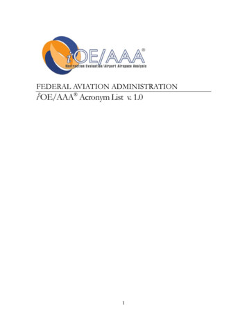
1. INTRODUCTION.This study was motivated by the need to investigate the fire hazard of carbon-fiber compositematerial for use in aircraft structures. In particular, it considers the material fabricated to Boeingmaterial specification (BMS) 8-276 by Toray Composites (America) in a quasi-isotropic lay-up[-45,0,45,90]2s of 16 plies. The material consists of resin and continuous carbon fibers, typically7 μm in diameter. The thickness of the material is 3.2 mm, and the two faces (smooth andrough) along with the edge view are shown in figure 1.Figure 1. Toray Carbon-Fiber Composite: Smooth Face, Edge, and Rough Face, Left to RightThe density of the composite is 1530 30 kg/m3. Other physical properties of the composite arelisted below: Carbon fiber density 1750 kg/m3Volume fraction of carbon in the composite 0.60Resin density 1220 kg/m3Char fraction (typical) of resin alone in flaming combustion 0.25During heating or combustion, the resin material will vaporize and leave a char residue. Theescaping resin vapor must escape through closely spaced carbon fibers. This produces internalpressures in the composite, and the sample will swell. Therefore, the physical properties of thecomposite will change on heating as the resin vaporizes, because the composite expands inresponse to the internal pressure. First, the bulk density of the material decreases, then poresform, and finally, the thermal conductivity of the matrix decreases. The strength of the degraded1
material is not addressed in this report, but should be a consideration for the effects of fire on itsperformance. While the vaporization of the resin will allow a flame to form in combustion, theremaining char and carbon can burn as a surface oxidation (smoldering) and even produce acarbon monoxide flame near the oxidizing surface. Typically, surface combustion needs a hightemperature to be sustained, which is usually in excess of 500 C.The use of a carbon composite for aircraft construction can have advantages over aluminum. Forexample, aluminum will melt at 660 C in large fires. Typically, for a composite material, thedegradation temperature to cause burning is 300 -500 C, but it will maintain structural integrityduring burning.Fire produces complex effects in a new material application that are not always anticipated.Since fire is commonly assessed in standard tests, the performance of a new material is notalways fully determined. This lack of determination is due to limitations in the tests to indicatepass/fail only, tests designed for traditional materials, and typical scenarios. This report is notintended to address these limitations or scenario considerations, but the data in this report shouldprovide a sufficient basis to make these further analyses. This report will only address theproperties of the composite in combustion.The controlling variable in fire is the heat flux that the material is subjected to. Consequently,the full performance of a material can only be judged by displaying its behavior over anappropriate range of heat flux. This report describes the fire performance over a range of heatflux that encompasses the peak in typical fire situations ( 100 kW/m2) to the lowest or criticalflux that initiates its fire behavior. This report examines the degradation of the material and itsbehavior in ignition, burning, and flame spread. Special and standard apparatuses have beenused to make these measurements. In addition, the thermal, thermodynamic, and chemicaldegradation kinetics of the material were measured. It should be noted that heat flux in firewould arise due to the flame itself and the thermal feedback of heated surroundings. So, a fire ina confined space will accelerate due to thermal feedback, and oxygen depletion will deceleratethe fire.Therefore, the effect of oxygen is an important factor in combustion, and the use of oxygensupply sources on an aircraft can produce enhanced oxygen. No experiments were conducted toaddress enhanced oxygen effects, but the theoretical response of this variable is well known, andestimates can be made for its effects.2. EXPERIMENTAL MEASUREMENTS.Various apparatuses were used to obtain the data for thermal and combustion effects on thecomposite. The measurements comprise properties pertaining to thermal, chemical kineticdegradation, and combustion phenomena.Physical properties pertaining to sampledecomposition were also measured after combustion. The principal variable varied in themeasurements was heat flux, or temperature. The measurements and a description of theapparatus are discussed in the following section.2
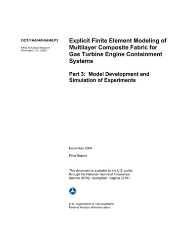
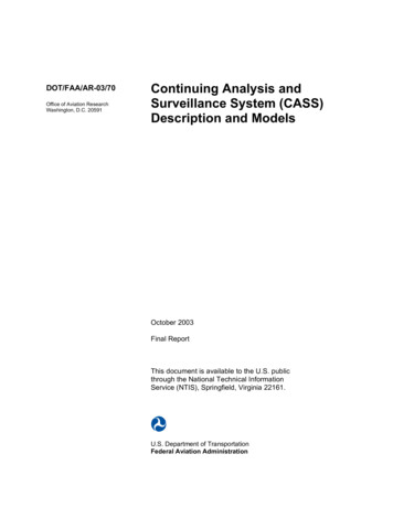
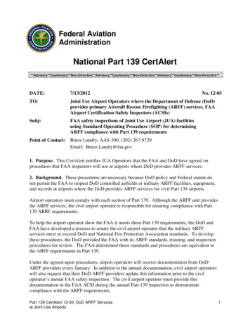
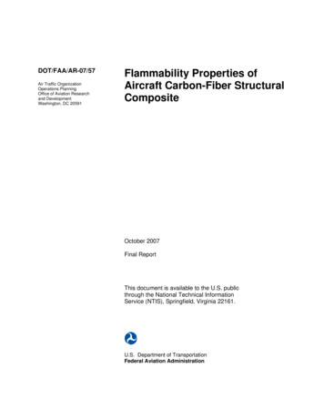
2.1 THERMAL CONDUCTIVITY.A flat power source was sandwiched between two identical materials to be measured (see figure2). The temperature difference ( T) across both samples of material was measured. At steadystate, half the power (recorded by current and voltage flow) constitutes steady heat conductionthrough the sample. Consequently, the thermal conductivity (k) can be measured fromk q ′′δΔT(1)where δ is the thickness, and q ′′ is the heat flow rate per unit area (heat flux).Figure 2. Conduction Apparatus: Heater Plate in Specimen Sandwich With Edge InsulationMeasurements were made for the composite by taking the power up in steps, and thereby raisingthe temperature across the specimen. The results, without accounting for any possible heatlosses, are shown in figure 3. A check on the accuracy of the method was made by using14-mm-thick ThermalCeramics Kaowool M-board for the sample. Then, the results werecompared to ThermalCeramics’ published results. The thicker, more insulating M-board causedend heat loss errors of up to 50%. This effect, in the denser, thinner composite suggested heatloss errors could cause a reduction in the results of figure 3 of about 20%. A more accurate,standard test measurement method is recommended to determine the conductivity of thecomposite. This should be done over the temperature range relevant to burning, as indicated infigure 3.3
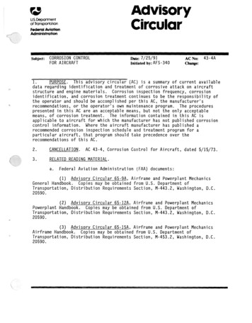
0.50.45k 0.023 x T(ºC)0.46k eOriginalComposition0.3DecompostionRangeof re ( C)Figure 3. Composite Thermal Conductivity Versus Temperature2.2 THERMODYNAMIC PROPERTIES.Specific heat and heat of decomposition were measured by differential scanning calorimetry(DSC) [1]. Appropriate calibrations were done to account for the baseline empty cup, and theheat losses from the heated cup to the surroundings. The sample was taken throughdecomposition, and then the residue (primarily carbon) was run separately to determine itsspecific heat. Three repeated runs were averaged for a final value. The results as a function oftemperature are shown in figure 4, where J Joules and K temperature in Kelvin.The microscale combustion calorimeter was also used to establish the complete heat ofcombustion of the volatiles [2]. It measures the energy of complete combustion per unit mass ofsample degraded as a function of the sample temperature. These results are shown in figure 5.The heat of complete combustion of the volatiles is determined as q′′ 1 dT .β(1 μ ) 0 mi .Δhc ,complete4(2)
Specific Heats per Original MassEffective Specific Heat (J/g-K original)30original C 0.75 0.0041 T (ºC) J/g-K originalPresidue CP,O 0.84 0.0035 T (ºC) J/g-K original2520Heat of DecompositionArea Under Curves Shaded152.07, 2.22, 3.12 kJ/gAverage 2.5 0.5 kJ/g10500100200300400500600Temperature ( C)Figure 4. The DSC Results, Specific Heat, and Heat of Decomposition(per Unit Mass of Original Sample)The heating rate, β, is 1 K/s, and the residue (char) fraction, µ, is 0.74.integration yields Δhc,complete 26.5 kJ/g volatiles.Energy Release Rateper Mass of Original Material (W/g)100η 96 J/g-K originalRun 1Run 2Run 3c80β 1 K/s60402000100200300400500600700800Temperature (ºC)Figure 5. Microscale Combustion Calorimeter Results5Performing the
2.3 KINETICS OF DEGRADATION.Standard thermal gravimetric analysis (TGA) was used to establish the degradation and massloss behavior of the composite in nitrogen. Several runs were made at different heating rates toobtain sufficient data to determine kinetic degradation parameters. A one-step, first-orderdecomposition model was assumed having activation energy (Ea) and the pre-exponential factor(ap) for the composite. The char fraction (µ) was also measured. The governing equation for themodel is [3]dα (1 α ) k (T )dt (1 μ )where(3)m 1m mimiα m f miμ 1 E aand m is the mass (i-initial, f –final), and k a p e RT is the Arrhenius rate. Based on equation 3,the activation energy and pre-exponential constant were determined for four TGA runs of 1 , 3 ,10 , and 30 C/minute at α mass loss rate corresponding to the peak decomposition rate. Theresult is shown in figure 6, and the kinetic parameters follow asEa 182 kJ/molap 9.67 x
16 Total Energy Released in Burning 17 17 Burning Rate of Carbon Fibers in Smoldering 17 . It can ignite with a pilot flame after preheating at a low heat flux. When it burns, the resin vapor is forced out of the fiber pores, and pressure causes th