Transcription
HVAC system size: Getting it rightRight-sizing HVAC systems in commercial buildings
SYRTGONMDepartment of MainMain RoadsRoadsDepartment of Public WorksDepartment of State Development,Trade and InnovationVERINDUCRC for Construction Innovation participantsENTRESEARCH
HVAC system size ― getting it rightPC Thomas and Steven Moller
Icon.Net Pty Ltd 2007Cooperative Research Centre for Construction InnovationLevel 9, L block, QUT Gardens Point2 George Street, Brisbane, Qld, Australia 4000Telephone: 61 7 3138 1393Email: enquiries@construction-innovation.infoWeb: www.construction-innovation.infoAll intellectual property in the ideas, concepts and design for this publication belongs toIcon.Net Pty Ltd.This industry publication is an outcome of the CRC for Construction Innovation project“Right-sizing Air Conditioning Systems”. The lead authors from the project team werePC Thomas, Arup Australasia (now at Team Catalyst Pty Ltd) and Project leader, StevenMoller, CSIRO (now at Sustainable Built Environments) with other team members beingHelen Lewis (RMIT) and Gregory Nowak (Rider Hunt).For more information on the project and the final research report refer p?id 395.The authors, the Cooperative Research Centre for Construction Innovation, Icon.Net Pty Ltd,and their respective boards, stakeholders, officers, employees and agents make norepresentation or warranty concerning the accuracy or completeness of the information inthis work. To the extent permissible by law, the aforementioned persons exclude all impliedconditions or warranties and disclaim all liability for any loss or damage or otherconsequences howsoever arising from the use of the information in this book.ISBN 978-0-9803503-8-8AcknowledgementsThe authors would like to thank the following organisations and people for their generoussupport and assistance, without which this project could not have been successful: Richard Hough of Arup, who supported this project from the beginning, as did KenStickland and Graham Paul the CSIRO for assistance and support, particularly Peter Newton Greg Nowak of Rider Hunt who put the conceptual framework for the LCC analysisthen carried out ably by Jason Moradi Alison Terry from RMIT who kept the project on track and did the occupant surveyresearch, with support from Helen Lewis the building owners and operational staff from each of the case study buildings whowere patient and helpful to a fault, and who for reasons of confidentiality, we cannotname.Project partners
Contents1.0Project overview12.0Symptoms of over-sizing13.0Impacts of over-sizing3.1Component over-sizing3.2Inefficient operation3.3Cost impact3.4Thermal comfort223474.0Barriers to right-sizing4.1Occupancy loads4.2Internal loads4.3Temperature setpoints4.4Discrete design process4.5Overshadowing4.6Unknown tenants4.7Contractual obligations888999995.0Over-sizing recommendations5.1Challenge “rules of thumb”5.2Accurate load estimation5.3Dynamic calculation methods5.4Systems approach5.5Design for flexibility5.6Separate high load areas5.7Integrated design process5.8Recognise the value of design5.9Commissioning and maintenance5.10 Life Cycle Cost Analysis5.11 Mandatory disclosure1010101010111111111212126.0Future work127.0References13
CRC for Construction Innovation1.0Project overviewMany heating, ventilating and air-conditioning (HVAC) systems installed in commercialbuildings, have more capacity than is ever required to keep the occupants comfortable. Such“oversized” HVAC systems can have negative effects on the environment, on occupantcomfort, as well as on the economic outcomes for the building.Studies of two large office buildings ― Case study 1 in Sydney and Case study 2 inMelbourne ― were the focus of this project. The project team’s approach was to: study as-built drawings and specifications undertake site visits perform technical and economic analyses hold interviews with members of the buildings’ design team, building managers andoccupants in order to obtain a wide range of perspectives organise and hold an industry workshop with input from consultants, contractors anddevelopers to get insights on the issue of HVAC over-sizing from a range ofviewpoints hold focus groups to get a user’s perception of comfort in the office spaces.Drawing on all of this material, this project collated and documented the following: the symptoms of over-sizing the impacts of over-sizing the barriers to right-sizing suggestions and solutions to reduce over-sizing.2.0Symptoms of over-sizingFor comfort cooling applications, standard design practice uses the concept of a “designday” ― conditions that are exceeded, on average, on 10 days per year. Thus the HVACsystem in a building will be fully loaded, that is, will run at full cooling capacity, on these 10days. Cooling systems can also operate fully loaded when removing heat built up after a hotweekend. The loading on the HVAC system will be reduced due to load diversity in theseinstances. Load diversity may be due to such elements as occupancy being less than designload, staff being on leave or otherwise out of the office, the installed and the operatingequipment load being less than the design load in many areas.If an HVAC system is undersized, there will be more hours per year when the plant isrunning fully loaded, and the system will not be able to hold indoor design conditions evenon a design day, let alone any hotter days; that is, temperatures in these air-conditionedspaces will rise.If an HVAC system is over-sized, it will never run fully loaded ― a log of chiller loading willreveal that utilised capacity will almost always be less than 80 or 90 percent of installedcapacity.Other symptoms that over-sized HVAC systems may exhibit are: frequent short cycling of individual chiller machines difficulty in maintaining design conditions during periods of high humidity excessive re-heat energy consumption.HVAC system size ― getting it right1
CRC for Construction InnovationSome of the conditions that must be fulfilled for the definition of “over-sized HVAC” system tobe warranted are as follow. System components and controls must have been correctly designed andcommissioned. If chilled water system flow rates are lower than designed, the chillerset will never be fully loaded. Cooling loads can also be reduced if outside air ratesare low or if space temperatures are not controlled within designed limits. The building must be fully occupied. False loading of heating and cooling systems must not be occurring; that is, if heatingis fighting cooling, due to dampers or valves leaking, the chiller plant may beartificially loaded, giving the impression of correct sizing. Spare capacity, intentionally included in the design, must be excluded from theanalysis. This spare capacity provides redundancy to cover breakdowns or anallowance for future increased tenant loads.This report studies over-sizing of HVAC systems; that is, when significantly more capacitythan is required to meet the design brief is installed on a large commercial building project.There is evidence in research literature of such over-sizing overseas. Surveys of 30 systemsin Wales (Knight and Dunn, 2004) and 50 systems in the UK (Crozier, 2000) concluded thatvirtually all systems were over-sized.3.0Impacts of over-sizing3.1Component over-sizingOver-sizing of cooling plant can mean that at least some of the following items are overspecified due to the flow-on effect across the whole HVAC system: chillers and cooling towers pumps, pipes and valves plant rooms, risers, and ductwork fans, motors, cables, switchboards, and sub-station variable air volume (VAV) boxes, grilles and registers.Analysis of the two case-study buildings in Sydney and Melbourne was undertaken todetermine whether over-sizing had occurred. A load estimate was made using design briefsand building simulation software. This was compared to the installed equipment in thebuildings. Chiller capacity was estimated to be over-sized by 34 percent in Case study 1 and10 percent in Case study 2.Significant flow-on changes in pump, fan and associated motor sizes were predicted byperforming a re-sizing exercise on the case-study buildings.Piping and ductwork can accommodate a range of flow rates for each discrete size ofdiameter (pipe) or cross-section (duct). Reviewing the case-study designs indicated thatthere was less potential to replace the smaller on-floor branches of piping or ductwork. Inmost cases, the existing pipe or ductwork was still the correct dimension to cater for thereduced flow.However, estimating changes in the size of main pipe and duct runs provided importantinsights. There can be large savings for both these components if the particular design is atthe limit of a pipe/duct size, and right-sizing of the HVAC system resulted in a step down insize for the main branches. However, there are significant advantages in ensuring that mainbranch pipes and ductwork are generously sized, as explained below.HVAC system size ― getting it right2
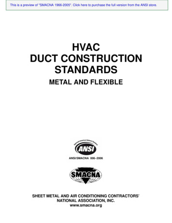
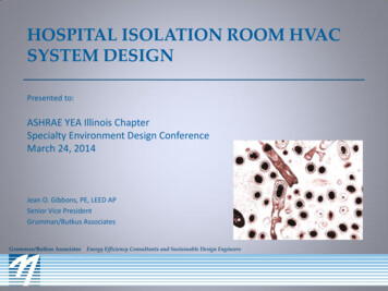
CRC for Construction InnovationReduction in the size of the main ducts could potentially reduce riser size requirements, witha possible increase in nett lettable area (NLA). However, in the authors’ experience, manybuildings have insufficient riser areas, forcing the mechanical engineer to design with highair velocities (and high static pressure) in associated ductwork. The result is significantlyincreased fan motor sizing and energy use for every single hour of fan operation. Reducingriser sizing is false economy!The impacts on cable sizes and switchboards were not studied in detail for these casestudies. However, it is anticipated that cable sizes would be affected in a similar way to pipesand ductwork. The potential for a commercially viable reduction in cable diameterspecification for larger components is more likely, as compared to cable size reductions foron-floor electrical circuits.3.2Inefficient operationOver-sized plant will operate inefficiently on a number of levels, as described in this section.Since the entire system is over-sized to handle even the peak design day conditions, almostall installed equipment and machinery will operate at low part load factors for largepercentages of their total operational time.One of the symptoms of over-sizing has already been mentioned, that of chiller logsproviding proof that a significant fraction (20% or more) of installed chiller capacity is neverused. Figure 1 plots the predicted outputs from a building energy simulation model that showestimated run time at various part load capacities for a single chiller plant room. The graphsdisplay a right-sized chiller (Chiller 1) and an over-sized chiller (Chiller 2). It is clearly seenthat the over-sized chiller runs most of the time at below 30 percent of rated capacity.1200Chiller 1Chiller 2Hours of %5060%6070%7080%8090%90- 100%100%Percentage Part LoadFigure 1Estimated run time at various part load capacities for a single chiller plantroom design — Chiller 1 (right-sized chiller) and Chiller 2 (over-sized chiller)HVAC system size ― getting it right3
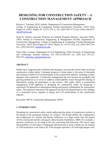
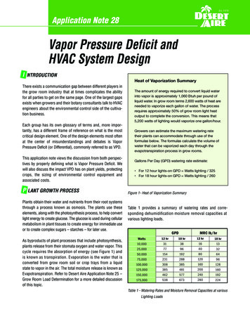
CRC for Construction InnovationAnother symptom of over-sizing is intermittent plant operation. This occurs when thediversified loads, during off-peak conditions, are so small that the cooling plant is unable toturn down to low load levels that allow the plant components to operate in a stable manner.This results in frequent stop-and-start operation, which could lead to shorter mean timebetween failures, and higher maintenance costs.Over-sized fans on variable-speed drives (VSD) will turn down to the lowest speed possibleand work as a virtual constant speed system. There is no control of flow in such a situation.This is illustrated by Figure 2 which plots simulated annual results for the operation of anover-sized fan system.4500NorthWestSouthInteriorInterior EastEast4000Hours of 0%3040%4050%5060%6070%7080%8090%90- 100%100%Percentage Part LoadFigure 2Simulated results depicting annual operation of a VSD controlled, oversizedAHU (air-handling unit) fans. The fans turns down to the lowest allowed partload (30% in this case) for approximately 60 percent of operational hours.Air volume at this lowest speed setting may still be too high, and excessive re-heat energyuse can be another symptom of over-sizing.Cost impact3.3Components with the largest capital cost penalties in an over-sized HVAC system design arethe major items of cooling plant; namely chillers, pumps and cooling towers.Other components like air-handlers (fans, motors and coils), pipework and ductwork can alsohave significant cost penalties, because of the large quantities involved.Right-sizing would lead to energy-efficient operation, resulting in annual energy and energycost saving. Additionally, savings in maintenance from lower equipment breakdown rateswould result as the systems would operate for a greater number of hours nearer their designpoint.HVAC system size ― getting it right4
CRC for Construction InnovationTable 1 provides the results of a costing exercise for Case-study 1 ― the higher level ofover-sizing (chillers estimated to be oversized at 34%). A typical floor plate was modelled,using a whole building energy simulation program. Estimates of peak demands with detailedglazing and geometry were entered into the model and the results used to recalculate plantcapacities. On-floor loads were also calculated and AHU sizes were recalculated. Thesedifferences were costed and listed in Table 1. In this instance, the estimated savings onmain plant are seen to be substantial, almost 29 percent for cooling towers and 21 percentfor chillers. Savings on air-handlers are estimated at 24 percent. In this project, the predictedabsolute savings are well in excess of 0.5 million.The degree of ove
Chiller capacity was estimated to be over-sized by 34 percent in Case study 1 and 10 percent in Case study 2. Significant flow-on changes in pump, fan and associated motor sizes were predicted by performing a re-sizing exercise on the case-study buildings. Piping and ductwork can accommodate a range of flow rates for each discrete size of diameter (pipe) or cross-section (duct). Reviewing the .