Transcription
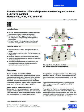
Bulletin H-TECH 06High-Pressure ValvesSeries H
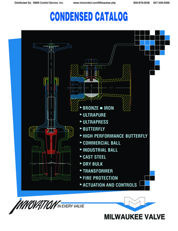
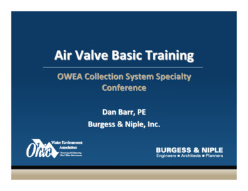
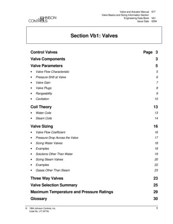
The H Series Leak-Proof, High-Pressure ValvesVersa Products Company has been supplying high qualitypneumatic and hydraulic directional control valves andcomponents for over 50 years. We have built a reputation forquality that is unsurpassed in a wide range of markets for highperformance solenoids, pneumatic relays and resets andrelated components.Versa’s H Series is a range of leak-proof high-pressure valvessuitable for low viscosity fluids that are ideally suited for theunique needs in the most demanding markets and applications.Low viscosity fluid may be mineral oils, high water based fluids,compressed air or natural gas. Standard valves are rated forhydraulic fluids up to 10.5 gpm (40 l/min) in 2-way and 3-wayfunctions.Corrosion resistant materials.Standard materials are 316stainless steel for compatiblywith the widest range of mediasin almost any service.Apply Versa’s optional pneumatic service suffix and manyforms of gas can be controlled in various flow configurations.Valves are available with solenoid or pilot actuation and manualoverrides are standard. H Series valves are constructed ofstainless steel materials, as standard. All valves are manifoldmounted style with a number of standard manifoldconfigurations. Custom manifolding, circuitry and nonstandard functions can be a easily developed upon request.Major market applications are within the Oil and Gas industry,however H Series valves have been successfully applied inmining, steel, utility, fire-fighting, desalination and more.Standard override on every valve.Easy setup of equipment. Fieldtesting and equipment troubleshooting are greatly simplified.Ceramic sealing for leakfree sealing. Hardened sealingsurfaces for long service life.Materials compatible with thewidest range of medias andservices.Dynamically balancedsealing assembly.Regardless ofapplication pressures,internal components arebalanced via theoperating fluid to assurepositive shifting.No false shiftsdue to pressure spikes.Actuator shifting lever.The ASL assures positiveshifting through mechanicaladvantage. The ASL alsoreduces the force or powerrequirements to allow for anumber of actuators. Manydifferent solenoids are offeredwith low wattage requirements.A pilot actuator may also beselected, shifting the valve witha low-pressure signal.Pullout design.Internals pullout foreasy removal of keyparts simplifyingservice andmaintenanceModular design forstandardized components.This modular design allowsfor field conversions and theavailability of replacementassemblies. O’ Ring static sealing.Positive sealing viastandard O’ rings.No custom or flat gasketsto leak.Standard O’ ringsavailable in every tool bin.Manifold mounted. All valves aremanifold mounted for easy removal.No need to disturb system piping. Allpiping accomplished in the manifold base.2
H Series SpecificationsFunctionThe H Series is a line of stainless or aluminum manifold mounted valves available as 2-way or 3-way, normally open or closedfunction. Valve function is not field convertible therefore specify function as required. For other functions consult factory.Service MediaHydraulic Service. The standard H Series valve is rated for hydraulic media. Typical hydraulic fluids are considered mineraloil, synthetic oils, water and water glycol. All applications to be confirmed by factory. High-pressure hydraulic service isalso available, see pressure chart.Pneumatic Service. H Series valves are rated for pneumatic service, suffix detail option required. See pressure chart.Pneumatic service would be high-pressure air, inert gasses, natural gas and sour gas. All valves, with pneumatic serviceoption are rated for non-lube service, however lubrication is recommended when feasible.Flow/Pressure RatingsFlowValve SizeCvGPM (l/min)H02H03H06H100.060.230.791.90.3 (0.9)1.2 (5)4.0 (15)10.5 (40)Pressure RatingHydraulicPneumaticStandard Valve Suffix –HP2Suffix –ASSuffix –AS1no suffixPSI (bar)PSI (bar)PSI (bar)PSI (bar)10,000 (690)6,000 (414)6,000 (414)5,000 (345)N/A10,000 (690)N/AN/AN/A2,320 (160)2,320 (160)1,450 (100)N/A3,625 (250)3,625 (250)N/APressures listed above are maximum body pressures. Minimum pressures arebased on actuator selection, see actuator section for minimum pressure ratings.All valves are tested prior to shipment.Test pressures are 1.5 times rated pressures for hydraulic service.Pneumatic valves are tested at rated pressures.For higher flows and or pressures contact factory.General SpecificationsTemperature rangeFiltrationTemperature range is based on actuator selection.Please see page 4 for temperature information.Hydraulic Service:10 micron (H02 size)20 micron (H03, H06 and H10 size)Pneumatic Serivce: 20 micron (all sizes)Materials of ConstructionMain Body:316 Stainless steel (standard)430F Stainless steel (optional, add suffix -430)Aluminum, anodized (optional, add suffix –AL)Seals, dynamic:Ceramic seal with stainless steel seat (hydraulic service, standard and suffix – HP2)Ceramic seal with engineered polymer seat (pneumatic service, suffix –AS and –AS1)Seals, Static:BunaFasteners:Stainless steelManifold:See manifold sectionVersa exercises diligence to assure that information contained in this catalog is correct, but does not acceptresponsibility for any errors or omissions. Versa also reserves the right to change or delete data or productsat any time without prior notification. To be sure the data you require is correct, consult factory.3
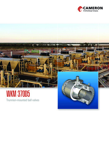
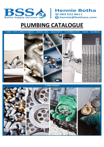
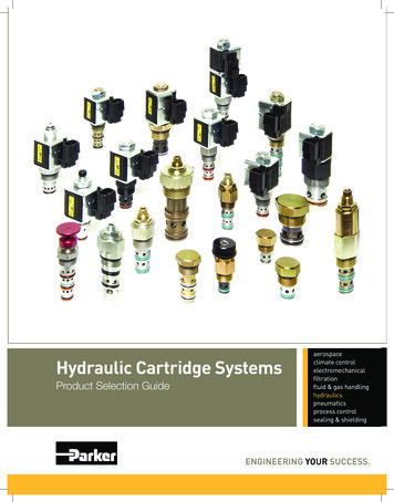
Suffix Detail: XBHazardous Location – Flameproof – ATEX*Protection Classification: II 2G EEx de IIB H2 T4/T6Area Classification: ZONE 1Ingress Protection: IP54Voltage: 12 to 250 Volts AC or DCPower: H3 13 to 17 Watts, H6 20 WattsElectrical Connection: M20x1.5 w/PG16 cord gripTemperature Rating: T4: -4F to 158F (-20C to 70C)T6: -4F to 104F (-20C to 40C)ActuatorsXFSuffix Detail: XCHazardous Location – Flameproof – ATEX*Protection Classification: II 2G EEx d IIC T6Area Classification: ZONE 1Ingress Protection: IP65Voltage: Up to 250 Volts DCPower: 3 WattsElectrical Connection: M20x1.5Temperature Rating: T6 – 4F to 140F (-20C to 60C)XBSuffix Detail: XDHazardous Location – Intrinsic Safe – ATEXProtection Classification: II 2G EEx ia IIC T5/T6Area Classification: ZONE 1Ingress Protection: IP54Voltage: 5 to 24 Volts DCPower: up to 2 WattsElectrical Connection: PG7 cord gripTemperature Rating: T6 – 4F to 140F (-20C to 60C)T5 – 4F to 158F (-20C to 70C)XDSolenoidsSuffix Detail: XEHazardous Location – Encapsulation – ATEXProtection Classification: II 2G EEx me II T5/T6Area Classification: ZONE 1Ingress Protection: IP65 (Use – XEX for IP66/68)Voltage: 12 to 125 Volts DCPower: 3 WattsElectrical Connection: M20x1.5Temperature Rating: T6 – 4F to 122F (-20C to 50C)T5 – 4F to 140F (-20C to 60C)XCXEPilotsLatchesSuffix Detail: HPHydraulic PilotSuffix Detail: XFGeneral PurposeArea Classification: NoneIngress Protection: IP54Voltage: 12 to 250 Volts AC or DCPower: H2/H3 13 Watts, H6 36 WattsElectrical Connection: PG9 cord gripTemperature Rating: -4F to 176F (-20C to 80C)*Consult factory for North American RatingsSuffix Detail: LP-1Latching Manual ResetOperation: Latches in the de-energizedposition. With loss of solenoid (or pilot)signal, the valve shifts closed and cannotbe re-shifted until manually reset.Suffix Detail: APPneumatic Pilot4
H Series Quick Reference Part Number Selector(Part numbers listed below are for standard hydraulic service. For other applications, suffix optionsare required. Part numbers include valve and actuators only. A manifold is required to completethe assembly part number. See page 6 for manifolds.)Solenoid actuated2-Way and 3-Way normally closed 2-position single solenoid, spring return valvesValveFunctionEEx deSolenoidEEx dSolenoidEEx iaSolenoidEEx meSolenoidGeneral PurposeSolenoidH022-Way NCN/AHSG-20201-XC-*See note 1HSG-20201-XD-*See note 1HSG-20201-XE-*See note 1HSG-20201-XF-*See note 13-Way NCN/AHSG-30201-XC-*See note 1HSG-30201-XD-*See note 1HSG-30201-XE-*See note 1HSG-30201-XF-*See note 12-Way NCHSG-20301-XB-*See note 1HSG-20321-XC-*See note 2HSG-20321-XD-*See note 2HSG-20321-XE-*See note 2HSG-20301-XF-*See note 13-Way NCHSG-30301-XB-*See note 1HSG-30321-XC-*See note 2HSG-30321-XD-*See note 2HSG-30321-XE-*See note 2HSG-30301-XF-*See note 12-Way NCHSG-20601-XB-*See note 1HSG-20621-XC-*See note 2HSG-20621-XD-*See note 2HSG-20621-XE-*See note 2HSG-20601-XF-*See note 13-Way NCHSG-30601-XB-*See note 1HSG-30621-XC-*See note 2HSG-30621-XD-*See note 2HSG-30621-XE-*See note 2HSG-30601-XF-*See note 12-Way NCHSG-21031-XB-*See note 2HSG-21021-XC-*See note 2HSG-21021-XD-*See note 2HSG-21021-XE-*See note 2HSG-21021-XF-*See note 23-Way NCHSG-31031-XB-*See note 2HSG-31021-XC-*See note 2HSG-31021-XD-*See note 2HSG-31021-XE-*See note 2HSG-31021-XF-*See note 2H03H06H10*Must add voltage code. See voltage code on page 6.Pressure Ratings:Maximum main body pressure is listed on flow/pressure chart. For higher-pressure hydraulic or pneumatic service selectsuffix option as required on flow/pressure chart. Minimum pressures are as follows:1. Minimum inlet pressure is 0 psi. Valve is a direct acting design.2. Minimum inlet pressure is 435 psi (30 bar). Valve is a solenoid-pilot design.All solenoid-operated valves are supplied with manual over-ride. XL solenoid valves are supplied with push button typeoverride. All other valves utilize lever type over-ride. Part numbers reflect normally closed valves. For normally openfunction change last digit on base number from 1 to 2.Pilot actuated2-Way and 3-Way normally closed 2-position single pilot, spring return valvesFunctionHydraulic PilotPneumatic PilotH03Valve Size2-Way, NC3-Way, H062-Way, NC3-Way, H10Consult FactoryPressure Rating:Maximum main body pressure is listed on flow/pressure chart. For higher-pressure hydraulic or pneumatic service selectsuffix option as required on flow/pressure chart. Minimum main body pressure for all pilot valves is 0 psi.Pilot shift pressure, all sizes: 50 psi (3.4 bar) Hydraulic/45 psi (3 bar) Pneumatic PilotPilot maximum pressure, all sizes: 3050 psi (210 bar) Hydraulic/232 psi (16 bar) Pneumatic PilotAll pilot operated valves are supplied with manual override. Part numbers reflect normally closed valves. For normally openfunction change last digit on base number from 1 to 2.5
SG ActuatorSG Solenoid operated, spring returnSP Pilot operated, spring return3 Function2 2-Way3 3-Way0302030610 XB Actuator Suffix OptionsAP Pilot Operated valve, Pneumatic signalHP Pilot Operated valve, Hydraulic signalXB Solenoid enclosure, Protection level EEx deXC Solenoid enclosure, Protection level EEx dXD Solenoid enclosure, Protection level EEx iaXE Solenoid enclosure, Protection level EEx meXEX Solenoid enclosure, Protection level EEx me, IP66/68XF Solenoid enclosure, General purpose, DIN ConnectorMain Valve SizeH02 SizeH03 SizeH06 SizeH10 SizeH E, SAMPLE CODE1 Spool Function1 Normally Closed2 Normally OpenedD024 VoltageD024 24 Volts, DCA120 120 Volts, 60 Hz.E110 110 Volts, 50 Hz.(consult factory for other voltages)H Seriesordering codesHow to specify a VersaSeries H part numberThe bold face captions(shown in color) explainthe meaning of the two largesample codes. Alternativecodes are shown beneaththe captions in black type.Not all options availablein all sizes. Pleaseconfirm part numberwith Versa Products Co.0 Solenoid-Pilot Operator(as determined by actuator)0 For Solenoid and pilot valves –No solenoid-pilot operator required.2 For Solenoid valvesH02 Solenoid-pilot operator required.3 For Solenoid valvesH03 Solenoid-pilot operator required.6 For Solenoid valvesH06 Solenoid-pilot operator required.430 NoneAL430HP2ASAS1LP1Valve Suffix Options 316 stainless steel, std. Aluminum body materials Stainless Steel Materials Hydraulic service valve,High pressure ratings Pneumatic service valve,Standard pressure ratings Pneumatic service valve,High pressure ratings Latching valve(consult factory for availability)H SeriesProductLine03 Size02 03 06 10 Main ValveH02H03H06H10SizeSizeSizeSizeM H SeriesSingle StationManifoldConsult factoryfor custom ormulti station manifolds3 Function2 2-Way3 3-Way03020304050607 Size1/81/43/81/23/411 Connection TypeConsult factory forAutoclave and SAE1 NPT2 ‘G’Material316 Stainless steel430 Stainless steelAL AluminumH3M–3031–3166
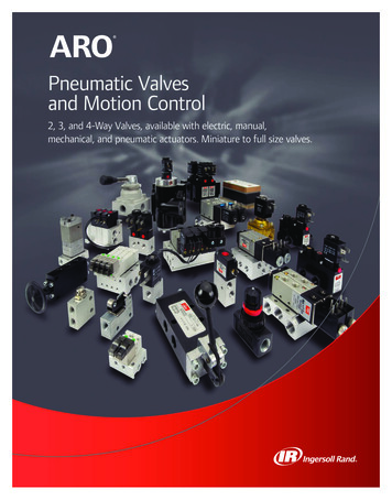
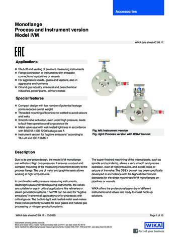
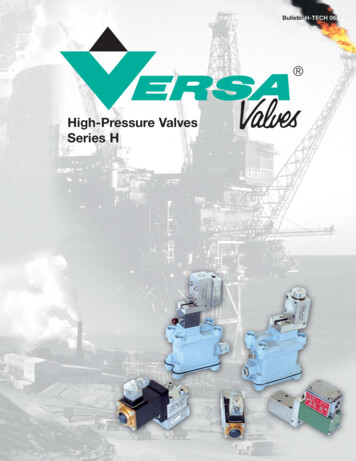
DAH Seriesdimensions12BSolenoid Actuated –General PurposeArea Classification3FCValve6AB4GCDEEFGBase 12DNote:AHDimensions are for referencepurposes only. Consult factoryfor layout drawings and actualdimensioning for exact valveselected as productdimensions change withoptions selected.12Valve3HSG-31021-XFinin7.89 200.5Cmm9.84 250inValveBase Number4.33 11012345678mm2.7670inFmm4.72 120Ginmm1.9750inHmm1.56 it EntrySolenoid EnclosureMain Valve BodyManifoldSolenoid-Pilot ValveManual Over-ridePilot ActuatorPilot PortGCBmm4FABase Number5BValves are shown on singlestation 3-way sub-plates. 2way function does not changeoverall sizes. Manual overridesfor the –XF solenoid option arepush button style. All othersolenoid options utilize a leverstyle override (similar to overrideon pilot actuated 0301-AP5.91 1503.94 1001.97501.57402.56651.18300.3180.41 10.5HSP-30601-AP6.30 1604.21 1071.97501.97502.76701.18300.47120.41 10.57
Versa has beensupplying theoil and gasindustry withpneumatic andhydrauliccomponentsfor over 50years. Wehave built areputation forquality that isunsurpassedin the marketfor highperformancesolenoids,pneumaticrelays andresets, andpilot valves.WARNINGS REGARDING THE DESIGN APPLICATION,INSTALLATION AND SERVICE OF VERSA PRODUCTSThe warnings below must be read and reviewed before designing a system utilizing,installing, servicing, or removing a Versa product. Improper use, installation orservicing of a Versa product could create a hazard to personnel and property.DESIGN APPLICATION WARNINGSVersa products are intended for use where compressed air or industrial hydraulic fluidsare present. For use with media other than specified or for non-industrial applicationsor other applications not within published specifications, consult Versa.Versa products are not inherently dangerous. They are only a component of a largersystem. The system in which a Versa product is used must include adequatesafequards to prevent injury or damage in the event of system or product failure,whether this failure be of switches, regulators, cylinders, valves or any other systemcomponent. System designers must provide adequate warnings for each sysem inwhich a Versa product is utilized. These warnings, including those set forth herein,should be provided by the designer to those who will come in contact with the system.Where questions exist regarding the applicability of a Versa product to a given use, inquiriesshould be addressed directly to the manufacturer. Confirmation should be obtaineddirectly from the manufacturer regarding any questioned application prior to proceeding.INSTALLATION, OPERATION AND SERVICE WARNINGSDo not install or service any Versa product on a system or machine without firstdepressurizing the system and turning off any air, fluid, or electricity to the system ormachine. All applicable electrical, mechanical, and safety codes, as well as applicablegovernmental regulations and laws must be complied with when installing or servicinga Versa product.Versa products should only be installed or serviced by qualified, knowledgeablepersonnel who understand how these specific products are to be installed and operated.The individual must be familiar with the particular specifications, including specificationsfor temperature, pressure, lubrication, environment and filtration for the Versa productwhich is being installed or serviced. Specifications may be obtained upon requestdirectly from Versa. If damages should occur to a Versa product, do not Operate thesystem containing the Versa product. Consult Versa for technical information.Versa Products Company Inc.22 Spring Valley RoadParamus, New Jersey 07652USAPhone: 201-843-2400Fax: 201-843-2931Versa BVPrins Willem Alexanderlaan 14297321 GB ApeldoornThe NetherlandsPhone: 01131-55-368-1900Fax: 01131-55-368-1909LIMITED WARRANTY DISCLAIMERAND LIMITATION OF REMEDIESVersa’s H Series products arewarranted to be free from defectivematerial and workmanship for a periodof three years from the date ofmanufacture, provided said H Seriesproducts are used in accordance withVersa specifications. Versa’s liabilitypursuant to that warranty is limited tothe replacement of the Versa productproved to be defective provided theallegedly defective product is returnedto Versa or its authorized distributor.Versa provides no other warranties,expressed or implied, except asstated above. There are no impliedwarranties of merchantability or fitnessfor a particular purpose. Versa’sliability for breach of warranty asherein stated is the only and exclusiveremedy and in no event shall Versa beresponsible or liable for incidental orconsequential damages.www.versa-valves.comemail: sales@versa-valves.com
For higher-pressure hydraulic or pneumatic service select suffix option as required on flow/pressure chart. Minimum pressures are as follows: 1. Minimum inlet pressure is 0 psi. Valve is a direct acting design. 2. Minimum inlet pressure is 435 psi (30 bar). Valve is a solenoid-pilot design. All solenoid-operated valves are supplied with manual .