Transcription
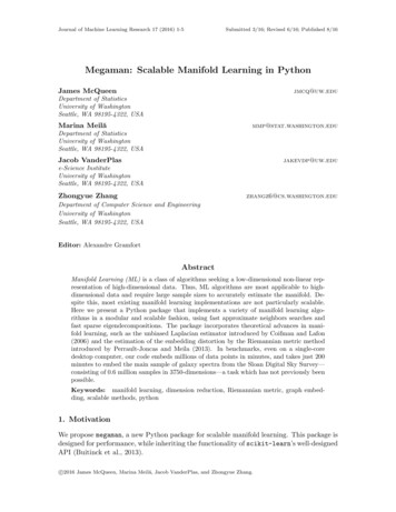
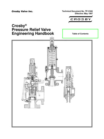
AccessoriesValve manifold for differential pressure measuring instruments3-, 5-valve manifoldModels IV30, IV31, IV50 and IV51WIKA data sheet AC 09.23Applications Shut-off, pressure compensating, purge and vent valvesfor differential pressure measuring instruments For gaseous and liquid aggressive media that arenot highly viscous or crystallising, also in aggressiveenvironments Process industry: Oil & gas, petrochemical, chemicalindustries, power generation, water and wastewaterSpecial features Low-wear design due to non-rotating spindle tip in thebonnet Low torque and smooth operation of valve handle even athigh pressure Enhanced safety due to blow-out proof bonnet design Customer-specific combination of valves and instruments(hook-up) on request Standardised centre distances of 37 mm and 54 mm,suitable for WIKA differential pressure gauges andcommonly used process transmittersFig. top: Model IV31, 3-valve manifoldFig. bottom: Model IV51, 5-valve manifoldDescription3-valve manifold, models IV30 and IV31The 3-valve manifold consists of two shut-off valves and onepressure compensating valve. The shut-off valves separatethe process from the differential pressure measuringinstrument. The pressure compensating valve enables thecompensation between side and side to avoid one-sidedoverpressure during commissioning and operation.5-valve manifold, models IV50 and IV51Compared to the 3-valve manifold, the 5-valve manifold isequipped with two additional vent valves. One vent valve perpressure side allows operators the targeted venting of one orboth pressure sides of the measuring arrangement.WIKA data sheet AC 09.23 05/2019Data sheets showing similar products and accessories:Needle valve and multiport valve; models IV10 and IV11; see data sheet AC 09.22Block-and-bleed valve, 2-valve manifold; models IV20 and IV21; see data sheet AC 09.19Through the non-rotating spindle tip, the wear of the sealingelements is reduced. This results, particularly with frequentopening and closing, in a noticeable increase in the servicelife.Through the blow-out proof design of the valve, workingsafety is improved, especially in applications with highpressure loading.As an option, WIKA offers the professional assembly ofvalves and pressure measuring instruments and also otheraccessories into a ready-to-install solution, also known as ahook-up. To ensure the performance of the complete system,an additional leak test is carried out on the hook-up.Page 1 of 11
SpecificationsValve manifold, models IV30, IV31, IV50 and IV51Standards usedDesign ASME B16.34, valves - flanged, threaded and welding end ASME B1.20.1, pipe threads, general purpose (inch) MSS SP-99, valves for measuring instrumentsTests API 598, valve inspection and testing ISO 5208, pressure testing of metallic valves with leakage rate A MSS SP-61, pressure testing of valvesMaterial requirements NACE MR0175 / ISO 15156, use in H₂S-containing environments in oil and gas production NORSOK M-630, specificaiton for use in pipelines (Norway)MarkingMSS SP-25, marking on valvesValve position(dimensions see page 6 ff.) Angled, pressure compensating valve in front, other valves arranged laterally 1) Radial, valves arranged side-by-side 2) Angled, for direct flange mounting 2)Process connection / instrumentconnection Vent connection¼ NPT female, plug screw is included in delivery, though not pre-fitted½ NPT female / G ¼ pressure screw½ NPT male / G ¼ pressure screw½ NPT female / G ½ pressure screw½ NPT male / G ½ pressure screw½ NPT female / process connection per IEC 61518 form B¼ NPT female / process connection per IEC 61518 form BMounting Without mounting holes Suitable for mounting bracket, with mounting holesBonnet design(see page 4 ff.) Standard version Extended handle versionBonnet options WithoutAnti-tamper version without padlock, ventAnti-tamper version without padlock, shut off and ventSmall T-bar handleT-bar handle from stainless steel 316LPadlock 6) WithoutWith padlock, ventWith padlock, shut offWith padlock, compensateWith padlock, vent and compensateWith padlock, shut off, vent and compensateSpecial design feature Without For oxygen, oil and grease free1) Option only for models IV30 and IV502) Option only for models IV31 and IV51WIKA data sheet AC 09.23 05/2019Page 2 of 11
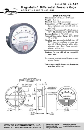
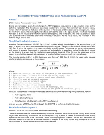
Functional diagram3-valve manifold5-valve manifoldCompensateCompensateShut offVentShut offShut offShut offVentMaterialWetted partsValve bodyBonnet bodySpindle tipSealing packing Stainless steel 316/316L (standard)Monel 400Hastelloy 276Others on request PTFE (standard) Graphite RTFEReinforced PTFE, material for optional certificate “Emission protection in accordancewith TA-Luft (VDI 2440) and ISO-15848-1”Non-wetted partsGland nut, valve spindle, seal bush,locking nut, locking pinStainless steel 316LHandle Stainless steel (standard) Stainless steel 316/316LWIKA data sheet AC 09.23 05/2019Page 3 of 11
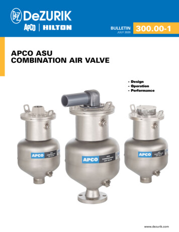
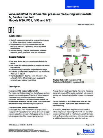
Bonnet, standard versionHandleColoured capGland nutValve spindleLocking nutSeal bushSealing packingLocking pinBonnet bodySpindle tipValve bodySpecificationsStandards complied with ASME VIII div. 1 and MSS SP-99 TA-Luft (VDI 2440) and ISO-15848-1 (option)Dust cap colour codeBlue: Shut offRed: VentGreen: CompensateSpindle tipNon-rotating, low-wear, blow-out-safeValve bore size4 mm [0.16 in]Valve seatAnti-tamper versionMetal-to-metal, back seat designAnti-tamper version with padlockExtended handle versionAccessory: Anti-tamper keyOrder number: 81640006WIKA data sheet AC 09.23 05/2019Page 4 of 11
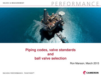
Pressure-temperature diagram700(10153)PTFE600(8702)GraphiteRTFE 1)Pressure in bar 0Temperature in C ( F)Material of thesealing packingPTFEGraphiteRTFE1)Max. permissible operating pressure in barat temperature in CMax. permissible operating pressure in psiat temperature in F690 bar at 38 C10,000 psi at 100 F276 bar at 204 C4,000 psi at 400 F420 bar at 38 C6,000 psi at 100 F209 bar at 538 C3,030 psi at 1.000 F420 bar at 38 C6,000 psi at 100 F276 bar at 180 C4,000 psi at 356 F1) Reinforced PTFE, material for optional certificate „Emission protection in accordance with TA-Luft (VDI 2440) and ISO-15848-1The minimum design temperature is -54 C [-65 F].For continuously low operating temperatures -54 C [ -65 F] a special design is needed.WIKA data sheet AC 09.23 05/2019Page 5 of 11
Dimensions in mm [in]3-valve manifold, model IV304, centre distance on instrument side: 37 mm [1.45 in]Valve position: Angled, pressure compensating valve in front, other valves arranged laterallyFor differential pressure gauge, WIKA model 732.513-valve manifold, model IV315, centre distance on instrument side: 54 mm [2,12 in]Valve position: Radial, valves arranged side-by-sideFor differential pressure gauges, WIKA model 732.14WIKA data sheet AC 09.23 05/2019Page 6 of 11
3-valve manifold, model IV316, centre distance on instrument side: 54 mm [2,12 in]Valve position: Angled, for direct flange mountingFor differential pressure measuring instruments with process connection per IEC 61518 form A or form BForm B: E.g. for differential pressure gauges, WIKA model 732.14, with process connection per IEC 61518Form A: E.g. for transmitters, WIKA model DPT-105-valve manifold, model IV504, centre distance on instrument side: 37 mm [1.45 in]Valve position: Angled, pressure compensating valve in front, other valves arranged laterallyFor differential pressure gauge, WIKA model 732.51WIKA data sheet AC 09.23 05/2019Page 7 of 11
5-valve manifold, model IV515, centre distance on instrument side: 54 mm [2.12 in]Valve position: Radial, valves arranged side-by-sideFor differential pressure gauges, WIKA model 732.14WIKA data sheet AC 09.23 05/2019Page 8 of 11
5-valve manifold, model IV516, centre distance on instrument side: 54 mm [2,12 in]Valve position: Angled, for direct flange mountingFor differential pressure measuring instruments with process connection per IEC 61518 form A or form BForm B: E.g. for differential pressure gauges, WIKA model 732.14, with process connection per IEC 61518Form A: E.g. for transmitters, WIKA model DPT-10WIKA data sheet AC 09.23 05/2019Page 9 of 11
AccessoriesOnly for versions with mounting option “R”: Suitable for mounting bracket, with mounting holesScope of delivery: 1 mounting bracket, 2 U-bolts, 2 screws for valve mountingMaterial: Stainless steelMounting bracket with mounting materialFormodelCentre distance oninstrument sideIV3154 mm [2,12 in]IV5154 mm [2,12 in]14267553IV3154 mm [2,12 in]14289800IV5154 mm [2,12 in]14289800WIKA data sheet AC 09.23 05/2019Alignment of the pipelineHorizontalVerticalOrder number14267553Page 10 of 11
ApprovalsLogoDescriptionCountry-CRNCanadaEAC (option)Eurasian Economic CommunityManufacturer‘s information and certificatesLogo Description-PMI 1) test certificate (option)Valve body-Certificate for oxygen versions (option)- Oil and grease free for oxygen per ASTM G93 level C- Sealing packing and lubricants in accordance with BAM requirements- Limits of the permissible operating ranges for pressure and temperature:420 bar at 60 C or 6,000 psi at 140 F90 bar at 200 C or 1,305 psi at 392 F-Emission protection in accordance with TA-Luft (VDI 2440) and ISO-15848-1 (option)- Tightness class: AH- Endurance class: C01- Temperature class: -29 . 180 C [-20 . 356 F]1) Positive material identificationCertificates 3.1 inspection certificate per EN 10204- Material certificate for the valve body per NACE (MR0103/MR0175)- Confirmation of pressure tests per API 598 2) 3.1 inspection certificate per EN 10204 (option)- Material certificate for all wetted parts per NACE (MR0103/MR0175)- Confirmation of pressure tests per API 598 2)2) Shell test: 15 s test duration with 1.5 times the permissible working pressureSeat test: 15 s test duration with 1.1 times the permissible working pressure05/2019 EN 02/2018 WIKA Alexander Wiegand SE & Co. KG, all rights reserved.The specifications given in this document represent the state of engineering at the time of publishing.We reserve the right to make modifications to the specifications and materials.WIKA data sheet AC 09.23 05/2019Page 11 of 11WIKA Alexander Wiegand SE & Co. KGAlexander-Wiegand-Straße 3063911 Klingenberg/GermanyTel. 49 9372 132-0Fax 49 9372 132-406info@wika.dewww.wika.de
MSS SP-99, valves for measuring instruments Tests API 598, valve inspection and testing ISO 5208, pressure testing of metallic valves with leakage rate A MSS SP-61, pressure testing of valves Material requirements NACE MR0175 / ISO 15156, use in H₂S-containing environments in oil and gas production NORSOK M-630, specificaiton for use in pipelines (Norway) Marking MSS SP-25, marking on valves .